

Page 1
M3535A/M3536A
User Training Workbook
HeartStart MRx
Page 2

Page 3

Notice
About This Edition
Publication number 453564045051
Edition 1
Printed in the USA
To determine the product level version to which this
guide applies to, refer to the version level on the back
cover of this book or on the label of the User
Documentation CD-ROM that accompanied the device.
This information is subject to change without notice.
Philips shall not be liable for errors contained herein or
for incidental or consequential damages in connection
with the furnishing, performance, or use of this material.
Edition History
Edition Print Date
1 September, 2006
Copyright
Copyright © 2006
Koninklijke Philips Electronics N.V.
All rights are reserved. Permission is granted to copy and
distribute this document for your organization’s internal
educational use. Reproduction and/or distribution
outside your organization in whole or in part is
prohibited without the prior written consent of the
copyright holder.
THIS PRODUCT IS NOT INTENDED FOR HOME
USE.
IN THE U.S., FEDERAL LAW RESTRICTS THIS
DEVICE TO SALE ON OR BY THE ORDER
OF A PHYSICIAN.
Medical Device Directive
The HeartStart MRx complies with the requirements of
the Medical Device Directive 93/42/EEC and carries the
mark accordingly.
0123
Manufacturer:
Philips Medical Systems
3000 Minuteman Road
Andover, MA 01810
Authorized EU-representative:
Philips Medizin Systeme Böblingen GmbH
Hewlett Packard Str. 2
71034 Böblingen
Germany
Canada EMC:ICES-001
China:
After Sales Service: Beijing MEHECO-PHILIPS Medical
Equipment Service Center.
After Sales Service Address: No. 208, 2nd District, Wang
Jing Li Ze Zhong Yuan, Chao Yang District, Beijing.
Postal code: 100102.
Telephone: 010-64392415.
Registration number: SFDA(I)20043211207.
Product Standard number: YZB/USA 52-21.
SMART Biphasic is a registered
trademark of Philips.
®
Microstream
of Oridion Medical Ltd. Smart CapnoLine™ is a
trademark of Oridion Medical Ltd.
Q-CPR™ is a trademark of Laerdal Medical.
The HeartStart MRx contains an Ezurio PC Card with
Bluetooth
wordmark and logos are owned by the Bluetooth SIG,
Inc. and any use of such marks by Ezurio is under license.
Other trademarks and trade names are those of their
respective owners.
Use of supplies or accessories other than those
recommended by Philips may compromise product
performance.
and FilterLine® are registered trademarks
®
wireless technology. The Bluetooth
For the Declaration of Conformity Statement, please see
the Philips Medical web site at http://
incenter.medical.philips.com/PMSPublic. Scroll over the
Quality and Regulatory Tab located in the upper left
corner of the window. Click to select Regulatory by
Modality. Then click to select Defibrillators and select
the entry for Declaration of Conformity (DoC)
Warning
Radio frequency (RF) interference from nearby
transmitting devices may degrade the performance of the
HeartStart MRx. Electromagnetic compatibility with
surrounding devices should be assessed prior to using the
monitor/defibrillator.
.
i
Page 4

This workbook should be used primarily for HeartStart MRx instructor-based end-user training, along
with the 453564045041 Instructor Guide. The workbook contains the following conventions:
"Voice" represents voice prompt messages
Text represents messages that appear on the HeartStart MRx display
Text represents options that appear on HeartStart MRx menus
[Soft key] represents soft key labels that appear on the display above the
button to which they correspond
ii
Page 5

1Table of Contents
1 Getting Acquainted 1
Lesson Introduction 1
Objectives 1
Lesson Presentation 2
Basic Orientation 2
Display View 7
Responding to Alarms 8
Password Security 9
Printing Waveforms 9
Continued Use 9
Return to Owner 10
Carrying Case and Accessory Pouch Assembly 11
Storing Accessories 12
Review 14
2 ECG and Arrhythmia Monitoring 15
Lesson Introduction 15
Objectives 15
Lesson Presentation 16
Monitor View 16
Preparation 17
Heart Rate and Arrhythmia Alarms 19
Displaying an Annotated ECG 22
Arrhythmia Learning/Relearning 23
Review 24
3 Semi-Automated
External Defibrillation 25
Lesson Introduction 25
Objectives 25
Lesson Presentation 26
AED View 26
Preparation 27
AED Mode 28
Shock Advised 29
No Shock Advised 30
Review 31
4 Manual Defibrillation
iii
Page 6

and Cardioversion 33
Lesson Introduction 33
Objectives 33
Lesson Presentation 34
Code View 34
Manual Defibrillation Preparation 35
Manual Defibrillation 36
Synchronized Cardioversion Preparation 37
Synchronized Shock Delivery 38
Review 39
5 Q-CPR™ 41
Lesson Introduction 41
Objectives 41
Lesson Presentation 42
Overview 42
Q-CPR Preparation 43
Q-CPR in Manual Defib Mode 45
Q-CPR in AED Mode 47
Review 49
6 Noninvasive Pacing 51
Lesson Introduction 51
Objectives 51
Lesson Presentation 52
Pacer Mode 52
Pacing View 52
Demand vs. Fixed Mode 53
Preparation 54
Demand Mode Pacing 55
Fixed Mode Pacing 56
Defibrillating During Pacing 57
Review 58
7 Pulse Oximetry Monitoring 59
Lesson Introduction 59
Objectives 59
Lesson Presentation 60
Monitoring SpO
Setting SpO2 Alarms 61
Setting Pulse Rate Alarms 62
Disabling SpO2 Monitoring 63
2
Review 64
60
iv
Page 7

8 Noninvasive Blood Pressure Monitoring 65
Lesson Introduction 65
Objectives 65
Lesson Presentation 66
Preparing to Measure NBP 66
Measuring NBP 67
Alarms 68
Review 69
9 Carbon Dioxide Monitoring 71
Lesson Introduction 71
Objectives 71
Lesson Presentation 72
Measuring EtCO
Setting Up the EtCO2 and AwRR Alarms 73
Disabling EtCO2 Monitoring 75
2
72
Review 76
10 Invasive Pressures Monitoring 77
Lesson Introduction 77
Objectives 77
Lesson Presentation 78
Overview 78
Pressure Measurement Set-up 78
Selecting a Pressure to Monitor 79
Pressure Waves 79
Zeroing the Pressure Transducer 81
Alarms 82
Pulse 83
Review 85
11 Temperature Monitoring 87
Lesson Introduction 87
Objectives 87
Lesson Presentation 88
Overview 88
Selecting a Temperature Label 88
Monitoring Temperature 88
Setting Temperature Alarms 89
Disabling Temperature Monitoring 89
Review 91
12 12-Lead ECG Monitoring 93
Lesson Introduction 93
Objectives 93
v
Page 8

Lesson Presentation 94
Preview Screen 94
Preparation 95
Acquiring the 12-Lead ECG 96
12-Lead Report 97
Adjusting Wave Size 98
Review 99
13 12-Lead ECG via Bluetooth Transmission 101
Lesson Introduction 101
Objectives 101
Lesson Presentation 102
Overview 102
Setting Up for Bluetooth Transmission 103
Transmitting to a Configured Site using Bluetooth 104
Transmitting to a Fax Number 105
Transmitting Stored 12-Lead Reports 105
Cancelling Transmission 106
Review 107
14 Vital Signs Trending 109
Lesson Introduction 109
Objectives 109
Lesson Presentation 110
Reviewing Trending Data 110
Tre nd i n g R e p o r t I n t er va l s 110
Scrolling in the Trending Report 110
Printing the Trending Report 111
Exiting the Trending Report 111
Review 112
15 Data Management 113
Lesson Introduction 113
Objectives 113
Lesson Presentation 114
Overview 114
Marking Events 115
Printing the Event Summary 115
Printing the Vital Signs Trending Report 115
Using Data Management - Internal Memory 116
Using Data Management - Data Card 116
Review 117
16 Maintenance 119
Lesson Introduction 119
Objectives 119
vi
Page 9

Lesson Presentation 120
Automated Tests 120
Ready For Use Indicator 120
Shift Check 121
Weekly Sh oc k Test 121
Operational Check 122
Battery Maintenance 124
Cleaning Instructions 125
Review 126
17 Review Answers 127
vii
Page 10

viii
Page 11

User Training Workbook
Lesson Introduction
This lesson provides an overview of the HeartStart MRx controls, indicators, operational modes, and
display views. It also provides general information on use of the device.
Objectives
Upon completion of this lesson, you should be able to:
1
1Getting Acquainted
1. Identify the physical features, controls, and indicators of the MRx.
2. Identify the purpose of various controls and indicators.
3. Identify the display view characteristics associated with MRx’s operating modes.
Notes:
________________________________________________________________
________________________________________________________________
________________________________________________________________
________________________________________________________________
________________________________________________________________
1
Page 12
1 Getting Acquainted Lesson Presentation
Lesson Presentation
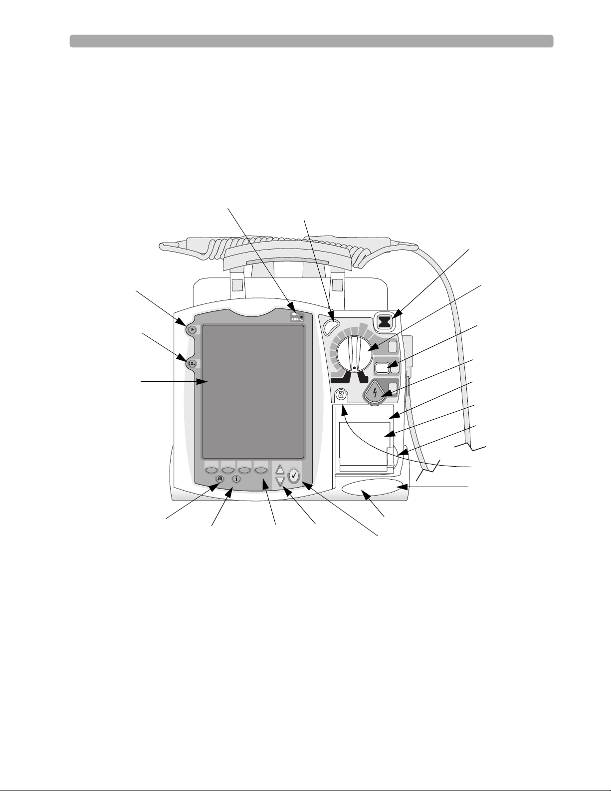
Basic Orientation
The MRx controls are organized to facilitate ease of use.
Front Panel
Mark Event
button
Lead Select
button
Display
External Power Indicator
Synchronized Cardioversion
(Sync) Button
c
n
y
S
u
u
n
n
a
a
M
M
A
D
120
b
b
150
i
i
100
f
f
e
e
70
D
D
l
l
a
a
50
30
20
15
1-10
n
O
O
n
P
acer
O
ff
AED
M
onitor
Ready For Use (RFU)
Indicator
Therapy Knob
dult
ose
170
200
S
elect
E
nergy
1
C
harge
Charge button
Shock button
2
S
hock
Printer (50mm)
3
Printer door
Printer door latch
Print button
Speaker
Alarm Pause button
(Label may appear with
or without an "X"
Summary
button
Soft keys (4 total)
Navigation buttons
Microphone
Menu Select button
through the triangle)
2
Page 13

Lesson Presentation 1 Getting Acquainted
Notes:
________________________________________________________________
________________________________________________________________
________________________________________________________________
________________________________________________________________
________________________________________________________________
________________________________________________________________
________________________________________________________________
________________________________________________________________
________________________________________________________________
________________________________________________________________
3
Page 14
1 Getting Acquainted Lesson Presentation
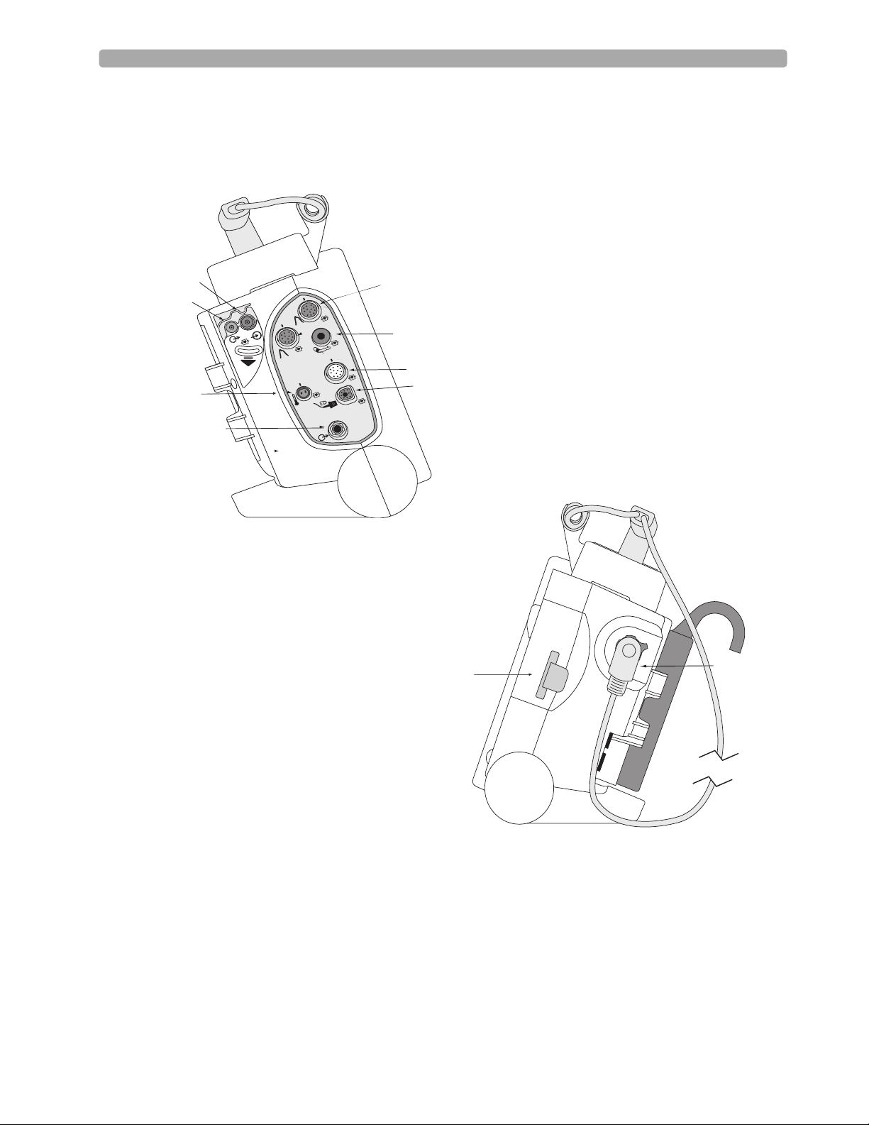
Side Panels
CO2 Inlet Port
CO2 Outlet Port
Temperature Port
ECG Out (Sync)
Jack
Invasive Pressure ports
2
O
C
™
a
e
r
t
s
o
r
c
i
M
1
NBP Port
2
m
G
C
E
G
C
E
ECG Port
SpO2 Port
Data Card
Therapy Connector
Notes:
________________________________________________________________
________________________________________________________________
________________________________________________________________
4
Page 15
Lesson Presentation 1 Getting Acquainted
Top Panel
Notes:
________________________________________________________________
________________________________________________________________
________________________________________________________________
________________________________________________________________
________________________________________________________________
________________________________________________________________
5
Page 16
1 Getting Acquainted Lesson Presentation
t
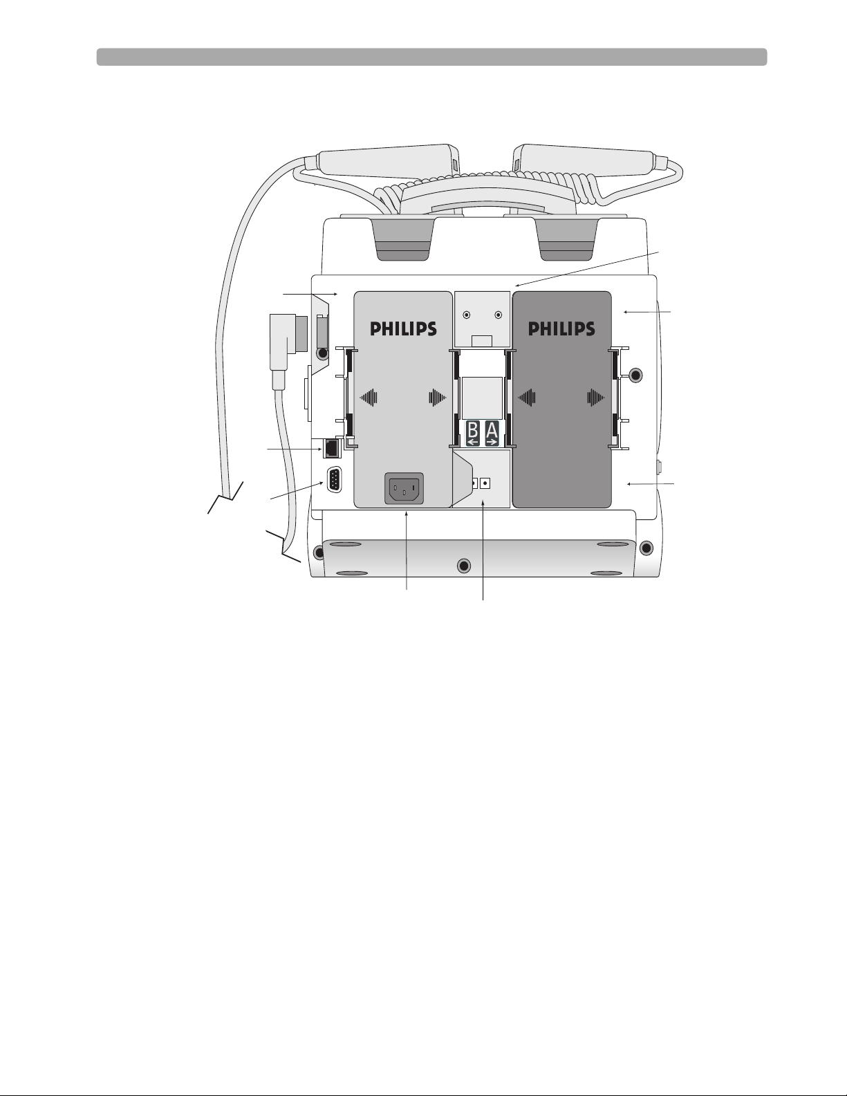
Back Panel
Bed Rail Hook Moun
Battery/AC
Compartment B
LAN Connection
Battery
Compartment A
RS 232 Serial Port
AC Power Module
DC Power Input
Notes:
________________________________________________________________
________________________________________________________________
________________________________________________________________
________________________________________________________________
________________________________________________________________
Battery
________________________________________________________________
6
Page 17
Lesson Presentation 1 Getting Acquainted
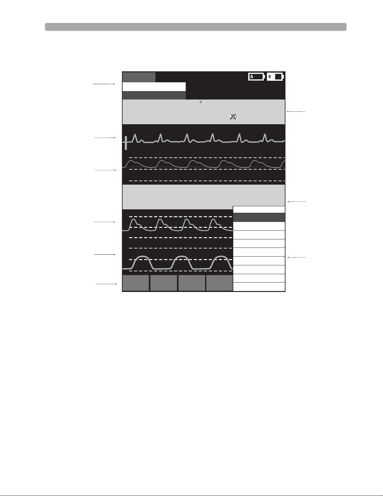
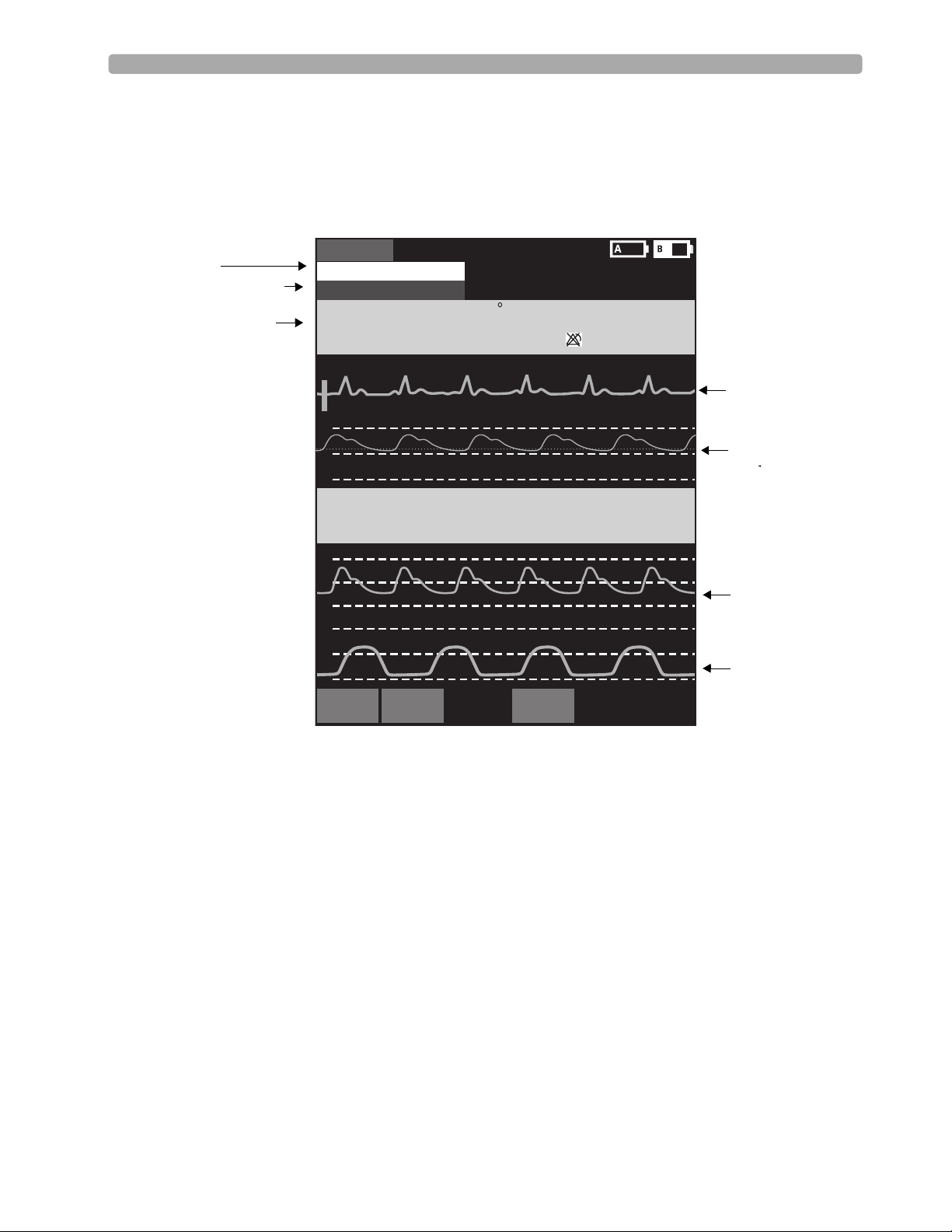
Display View
The MRx layout is as follows.
General Status
Area
Wav e
Sector 1
Wav e
Sector 2
Wav e
Sector 3
Wav e
Sector 4
Soft Keys
Mark Event
I
nop
ECG/HR
alarm
HR
bp
m
80
Primary ECG
AB
P
150
75
0
P
(95)
A
P
P
CO2
oftkey
mmHg
SYS
160
AB
118/77
30
15
0
60
30
0
S
#1
s
s
90
S
#2
A
oftkey
r
ea
120
50
PAP
24/10
(15)
P
atien
A
dul
T
emp
36.9 80
mmHg
I
A
D
16
0
S
oftkey
#3
10 Feb 2006 11:20
t nam
e
t
Non-
P
ul
se
C
39
.
0
.
0
36
SpO2 %EtCO2
100
100
S
oftkey
HH:MM:SS
P
ace
d
NB
bp
m
120/80
mmHg
90
38
M
a
in
Displayed Waves
Printed Waves
M
easurements
High Contrast On
#4
mmHg
P
SYS
160
90
(95)
AwRR
50
30
18
M
e
nu
V
olume
/
A
larms
Patient Info
T
rend
s
O
the
r
E
xit
q
10
120
rpm
Parameter
:
40
30
8
Block 1
Parameter
Block 2
Menu
Area
Notes:
________________________________________________________________
________________________________________________________________
________________________________________________________________
________________________________________________________________
7
Page 18

1 Getting Acquainted Lesson Presentation
Responding to Alarms
Follow the steps below to respond to an alarm condition.
1. Attend to the patient.
2. Identify the alarm(s) indicated.
3. Silence the alarm(s) using the Navigation and Menu Select buttons.
4. Address the alarm condition.
Notes:
________________________________________________________________
________________________________________________________________
________________________________________________________________
________________________________________________________________
________________________________________________________________
8
Page 19

Lesson Presentation 1 Getting Acquainted
Password Security
Access to Manual Defib and Pacer Modes may be password protected if enabled in Configuration.
Failure to enter the correct Manual Therapy Security password prevents manual defibrillation/
synchronized cardioversion delivery or pacing therapy. AED Mode is always available without a
password.
Printing Waveforms
To change wave forms for the second wave printed with a 50mm printer:
1. Press the Menu Select button.
2. Using the Navigation buttons, select the Printed Waves option and press Menu Select.
3. Using the Navigation buttons, select the wave form you want to print in Wave 2 and press Menu
Select.
To change wave forms for the second or third wave printed with a 75mm printer:
1. Press the Menu Select button.
2. Using the Navigation buttons, select the Printed Waves option and press Menu Select.
3. Using the Navigation buttons, select Wave 2 or Wave 3 and press Menu Select.
4. Using the Navigation buttons, select the wave form you want printed and press Menu Select.
5. Repeat Steps 2 through 4 for the other printed wave.
Continued Use
MRx’s Continued Use feature facilitates continued treatment of the same patient by retaining current
settings and the patient record when the MRx is turned off for less than 10 seconds or switching
between modes (e.g., Monitor, AED, and Manual Defib).
9
Page 20

1 Getting Acquainted Lesson Presentation
Return to Owner
To enable the Return to Owner feature:
1. Press the Menu Select button.
2. Select Other and press Menu Select.
3. Select Return To Owner and press Menu Select.
4. Press the [Activate] soft key.
5. Enter the number of days in the loan period and press Menu Select.
6. Press the [Exit Return-To] soft key.
To disable the Return to Owner feature:
1. Press the Menu Select button.
2. Select Other and press Menu Select.
3. Select Return To Owner and press Menu Select.
4. Press the [Deactivate] soft key.
5. Enter the password and press Menu Select.
6. Press the [Exit Return-To] soft key.
Notes:
________________________________________________________________
________________________________________________________________
________________________________________________________________
________________________________________________________________
________________________________________________________________
10
Page 21
Lesson Presentation 1 Getting Acquainted
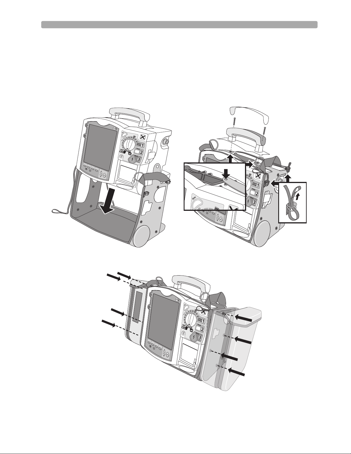
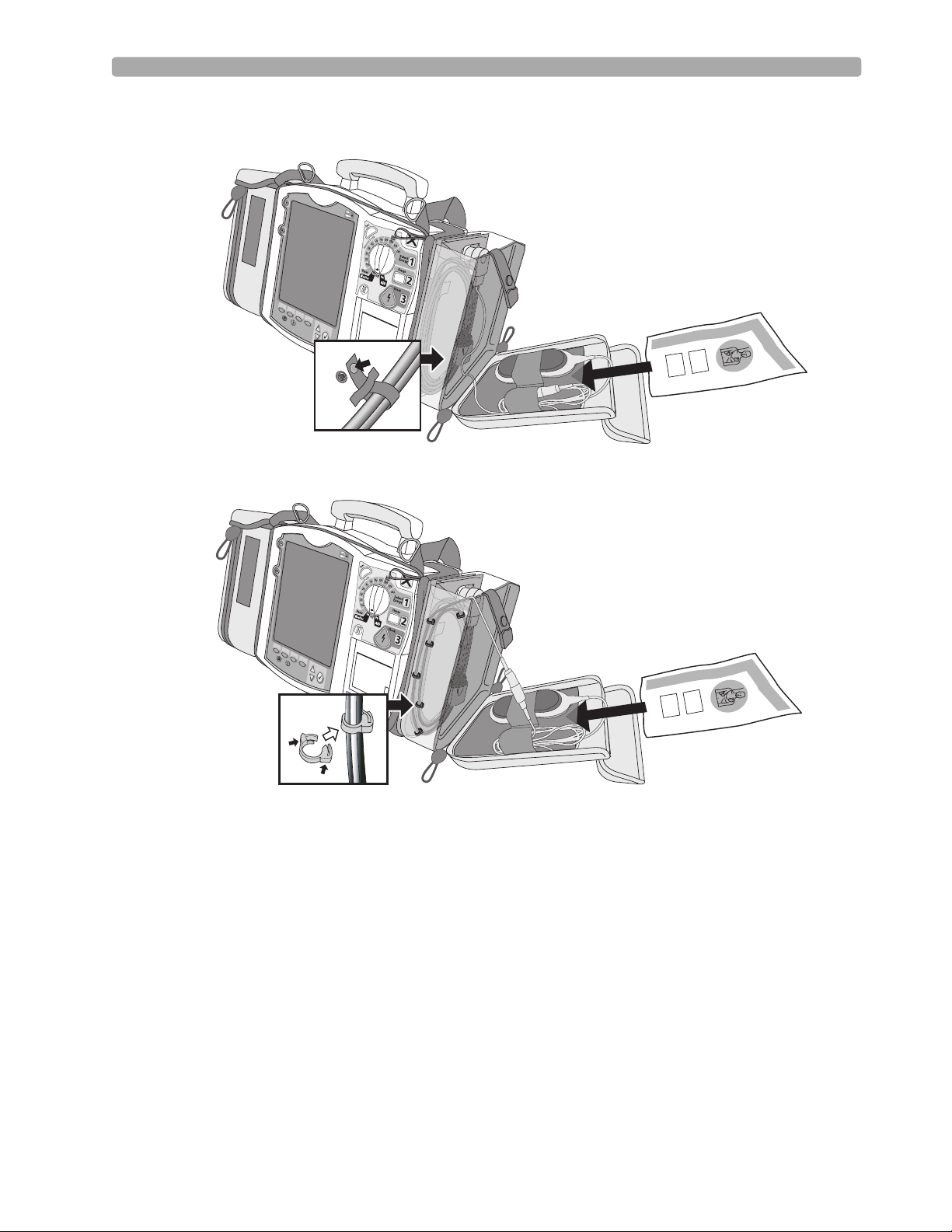
Carrying Case and Accessory Pouch Assembly
The following topics are for only customers who have carrying cases and accessory pouches, and require
assembly procedures and recommended accessory placement and storage. The following illustrations
show carrying case and accessory pouch assembly. Detailed directions can be found in the Setting Up
chapter of the MRx Instructions For Use.
11
Page 22
1 Getting Acquainted Lesson Presentation
(
(
(
(
(
(
(
(
(
(
(
(
(
(
(
(
(
(
(
(
(
(
(
(
(
(
(
(
(
(
(
(
(
(
(
(
(
(
(
(
(
(
(
(
(
(
(
(
(
(
(
(
(
(
(
(
(
(
(
(
(
(
(
(
(
(
(
(
(
(
(
(
(
(
(
(
(
(
(
(
(
(
(
(
(
(
(
(
(
(
(
(
(
(
(
(
(
(
(
(
(
(
(
(
(
(
(
(
(
(
(
(
(
(
(
(
(
(
(
(
(
(
(
(
(
(
(
(
(
(
(
(
(
(
(
(
(
(
(
(
(
(
(
(
(
(
(
(
(
(
(
(
(
(
(
(
(
(
(
(
(
(
(
(
(
(
(
(
(
(
(
(
(
(
(
(
(
(
(
(
(
(
(
(
(
(
(
(
(
(
(
(
(
(
(
(
(
(
(
(
(
(
(
(
(
(
(
(
(
(
(
(
(
(
(
(
(
(
(
(
(
(
(
(
(
(
(
(
(
(
(
(
(
(
(
(
(
(
(
(
(
(
(
(
(
(
(
(
(
(
(
(
(
(
(
(
(
(
(
(
(
(
(
(
(
(
(
(
(
(
(
(
(
(
(
(
(
(
(
(
(
(
(
(
(
(
(
(
(
(
(
(
(
(
(
(
(
(
(
(
(
(
(
(
(
(
(
(
(
(
(
(
(
(
(
(
(
(
(
(
(
(
(
(
(
(
(
(
(
(
(
(
(
(
(
(
(
(
(
(
(
(
(
(
(
(
(
(
(
(
(
(
(
((
(
(
(
(
(
(
(
(
(
(
(
(
(
(
(
(
(
(
(
(
(
(
(
(
(
(
(
(
(
(
(
(
(
(
(
(
(((
(((
((
(
(
(
(
(
(
(
(
(
(
(
(
(
(
(
(
(
(
(
(
(
(
(
(
(
(
(
(
(
(
(
(
(
(
(
(
(
(
(
(
(
(
(
(
(
(
(
(
(
(
(
(
(
(
(
(
(
(
(
(
(
(
(
(
(
(
(
(
(
(
(
(
(
(
(
(
(
(
(
(
(
(
(
(
(
(
(
(
(
(
(
(
(
(
(
(
(
(
(
(
(
(
(
(
(
(
(
(
(
(
(
(
(
(
(
(
(
(
(
(
(
(
(
(
(
(
(
(
((
((
((
((
((
((
((
((
(
(
(
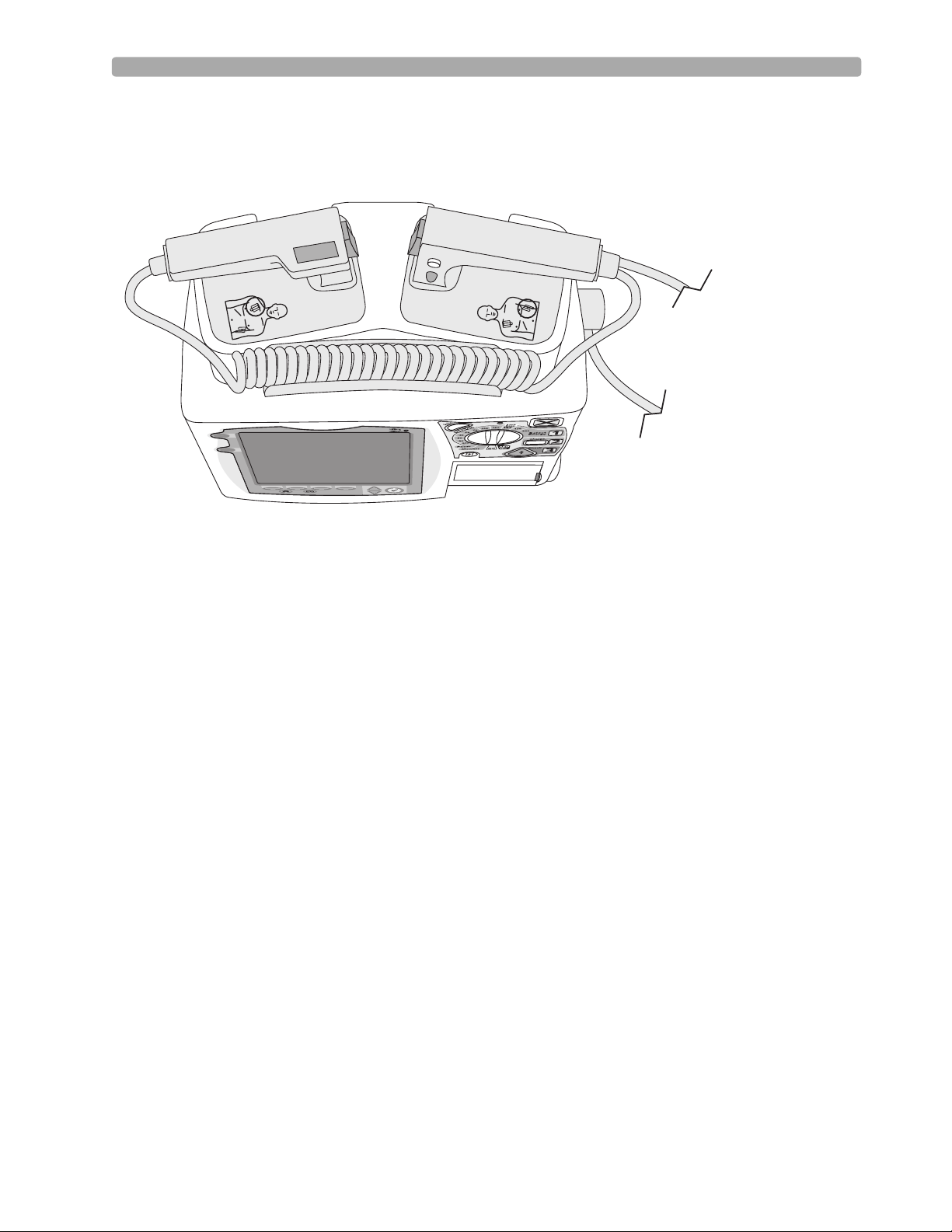
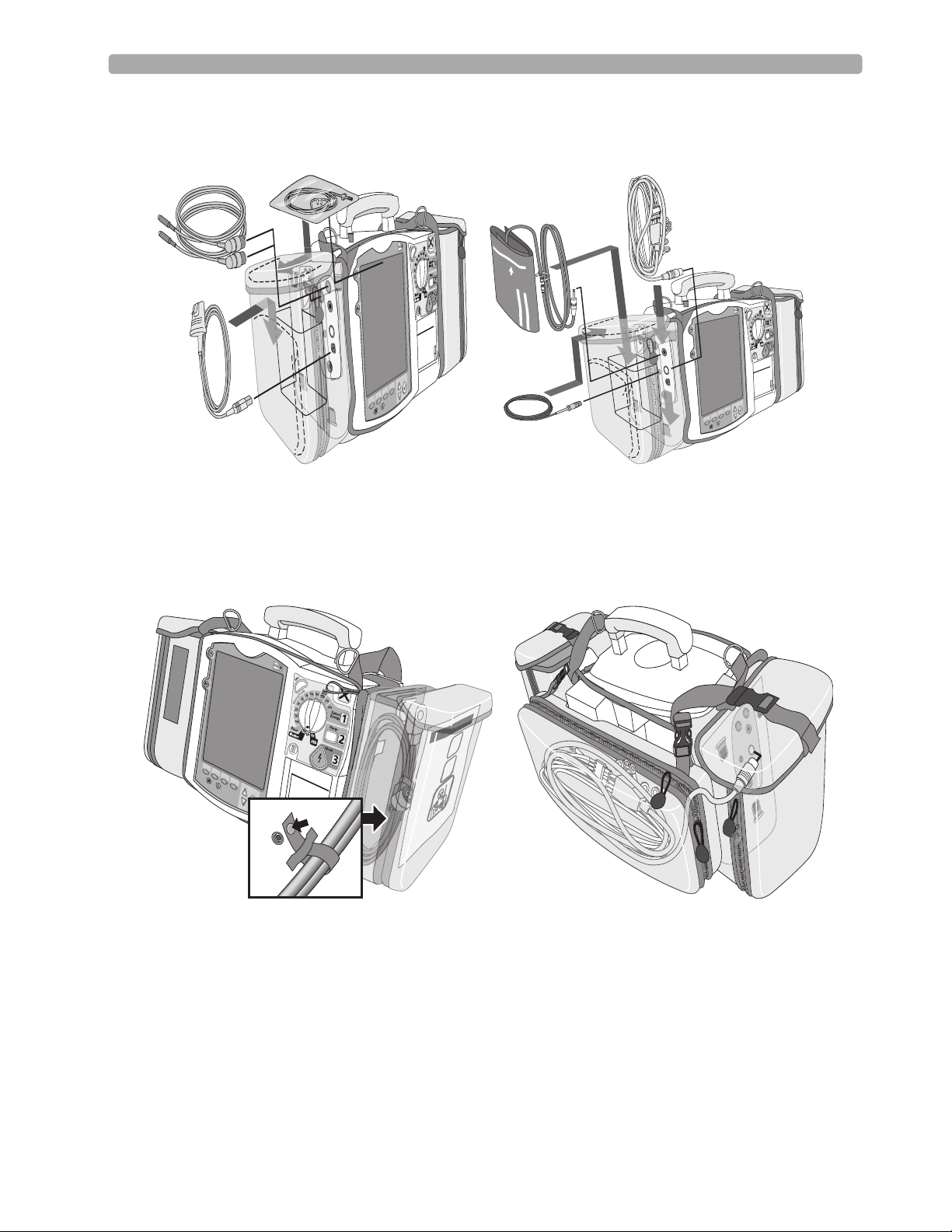
Storing Accessories
The following illustrations show parameter cabling and accessory storage in the left pouch.
Below is right pouch storage for the Therapy cable (on the left) and back pouch storage for ECG
electrodes (on the right).
(
(
(
(
(
(
(
(
(
(
(
(
(
(
(
(
(
(
(
(
(
(
(
(
(
(
(
(
(
(
(
(
(
(
(
(
(
(
(
(
(
(
(
(
(
(
(
(
(
(
(
(
(
(
(
(
12
Page 23
Lesson Presentation 1 Getting Acquainted
Here are recommended carry bag storage instructions for Q-CPR accessories.
Option 1
PHILIPS
Option 2
PHILIPS
Notes:
________________________________________________________________________________
________________________________________________________________________________
________________________________________________________________________________
________________________________________________________________________________
13
Page 24

1 Getting Acquainted Review
Review
Please answer the following questions related to MRx features, controls, and display view.
1. Identify at least three controls or buttons on the MRx involved with defibrillation.
a. ______________________________________
b. ______________________________________
c. ______________________________________
2. What does a solid red "X" and periodic audio chirp indicate on the RFU?
a. No battery is present
b. No power is available
c. A low battery condition
d. Defibrillation therapy may not be available
3. The arrhythmia algorithm uses the ECG in which Wave Sector for analysis?
a. 1
b. 2
c. 3
d. all of the above
4. You can select the ECG lead for Wave Sector 2 using either the Lead Select button or Displayed
Wave s menu. T or F
5. You should respond to alarms primarily by pressing the Alarm Pause button. T or F
14
Page 25

User Training Workbook
Lesson Introduction
This lesson describes the basic ECG and arrhythmia monitoring functions of the HeartStart MRx. It
briefly examines Monitor View, monitoring preparation, alarms, annotated ECGs, and arrhythmia
learning/relearning.
2
2ECG and Arrhythmia
Monitoring
Objectives
Upon completion of this lesson, you should be able to:
1. Locate pertinent information in Monitor View.
2. Prepare a patient for ECG and arrhythmia monitoring.
3. Set heart rate and arrhythmia alarms.
4. Display an annotated ECG.
5. Initiate manual relearning.
Notes:
________________________________________________________________
________________________________________________________________
________________________________________________________________
________________________________________________________________
________________________________________________________________
________________________________________________________________
15
Page 26
2 ECG and Arrhythmia Monitoring Lesson Presentation
Lesson Presentation
Monitor View
Monitor View is displayed when you turn the Therapy Knob to Monitor.
INOPs
ECG/HR Alarms
Heart Rate and
Alarm Settings
Mark Event
I
nop
ECG/HR
alarm
HR
bp
m
80
II
AB
P
150
75
0
AB
P
118/77
(95)
P
A
P
30
15
0
CO2
60
30
0
S
tar
t
NB
P
s
mmHg
SYS
160
s
90
12-L
A
r
ea
120
50
PAP
24/10
(15)
ea
d
Patient Name
A
T
emp
36.9 80
mmHg
I
A
D
16
0
10 Feb 2006 11:20
dul
t
Non-
P
ace
d
P
ul
se
bp
Z
r
100
ero
ess
m
90
38
C
.
0
39
36
.
0
SpO2 %EtCO2
100
P
NB
mmHg
P
120/80
(95)
mmHg
AwRR
50
30
MENU
02:42
q
120
SYS
160
:
40
10
90
rpm
30
8
18
Wave 1
Wave 2
Wave 3
Wave 4
Notes:
________________________________________________________________
________________________________________________________________
________________________________________________________________
________________________________________________________________
________________________________________________________________
________________________________________________________________
16
Page 27

Lesson Presentation 2 ECG and Arrhythmia Monitoring
Preparation
Follow the steps below to prepare for monitoring using multifunction electrode pads or electrodes.
Multifunction electrode pads
1. Prepare the patient’s chest (i.e., remove clothing, remove moisture from chest, and remove excessive
hair).
2. Apply multifunction electrode pads to the patient according to the pads package directions or your
organization’s protocol.
3. If not pre-connected, insert the pads cable into MRx’s green Therapy port.
4. Connect the pads to the pads cable.
Electrodes
1. Prepare the patient’s skin at appropriate electrode sites.
– If necessary, clip hair at the electrode sites (or shave sites if needed).
– Clean and abrade the skin at each electrode site.
– Dry the electrode sites briskly to increase capillary blood flow in the tissues and to remove oil
and skin cells.
2. Attach the snaps to the electrodes.
3. Apply the electrodes.
4. If not pre-connected, connect the ECG patient cable to the MRx.
Lead Selection
Use the Lead Select button to select the ECG lead for Wave Sector 1. To select a lead for Wave Sectors
2-4:
1. Press the Menu Select button.
2. Select Displayed Waves and press Menu Select.
3. Select the appropriate Wave Sector and press Menu Select.
4. Select the desired lead (with the clearest signal) and press Menu Select.
17
Page 28

2 ECG and Arrhythmia Monitoring Lesson Presentation
Practice Exercise 1
Attach a simulator and 3-, 5-, and 10-Lead ECG set to the MRx (5- or 10-Lead set preferred), set the
simulator to a normal sinus rhythm, and complete a variety of lead selections for Wave Sectors 2, 3,
and 4, as appropriate.
Questions
1. How do Wave 2, 3, and/or 4 menus differ from each other in terms of available leads? From the
Wave 1 m enu ?
2. What wave size(s) provide the clearest wave form?
3. What happens if you add a parameter?
Notes:
________________________________________________________________
________________________________________________________________
________________________________________________________________
________________________________________________________________
________________________________________________________________
18
Page 29

Lesson Presentation 2 ECG and Arrhythmia Monitoring
Heart Rate and Arrhythmia Alarms
Introduction
The ST/AR Basic Arrhythmia Algorithm generates heart rate and heart rate alarms, and can never be
disabled. Here are the various alerts MRx generates:
• Red alarms
• Yellow alarms
• INOP messages
HR/Arrhythmia Red Alarms
Alarm Message Condition Indicator Latching/
Non-Latching
Asystole No detectable beats for four
VFIB/VTACH A fibrillatory wave detected
VTACH Consecutive PVCs and HR
Extreme Brady 10 bpm below HR Low
Extreme Tachy 20 bpm above HR High
HR/Arrhythmia Yellow Alarms
Alarm Message Condition Indication Latching/
HR High The HR exceeds the configured
HR Low The HR is below the configured
PVC/min. High
(value > limit)
Pacer Not Capture No QRS following a pacer pulse Yellow alarm
Pacer Not Pacing No QRS or pacer pulse detected Yellow alarm
Red alarm message,
seconds in the absence of
Vfib
for four seconds
exceed defined limits
limit, capped at 30 bpm
limit capped at 200 bpm
(adult) or 240 bpm (pedi)
HR high limit
HR low limit
The number of detected PVCs in
a minute exceeds the limit of 15
(adult/pedi)
alarm tone
Red alarm message,
alarm tone
Red alarm message,
alarm tone
Red alarm message,
alarm tone
Red alarm message,
alarm tone
Yellow alarm
message, alarm tone
Yellow alarm
message, alarm tone
Yellow alarm
message, alarm tone
message, alarm tone
message, alarm tone
Latching
Latching
Latching
Latching
Latching
Non-Latching
Non-Latching
Non-Latching
Non-Latching
Latching
Latching
19
Page 30
2 ECG and Arrhythmia Monitoring Lesson Presentation
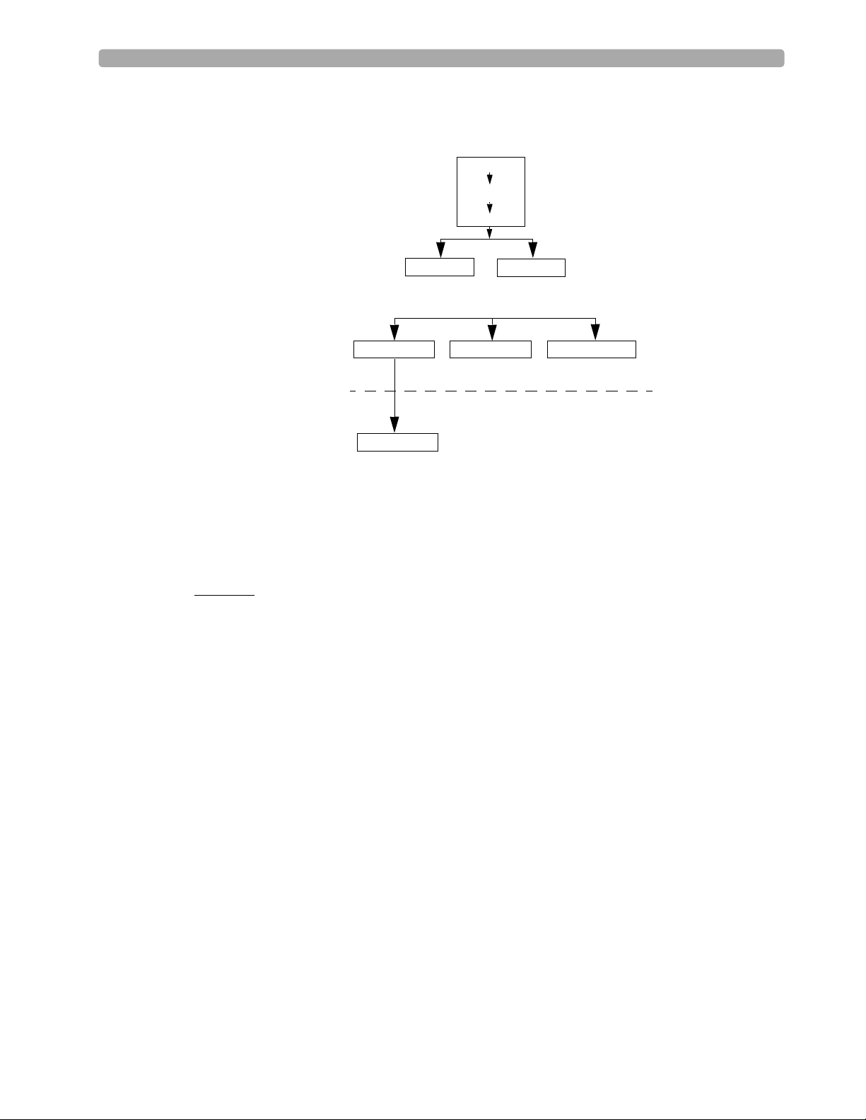
Alarm Chain for Basic Arrhythmia Monitoring
(RED ALARMS)
Asystole
V-Fib/V-Tach
V-Tach
Practice Exercise 2
Set the simulator and MRx to produce a variety of latching, non-latching, and INOP conditions, as
directed.
Questions
1. What do you see and hear when a red alarm goes off? A yellow alarm? An INOP message?
Frequent PVCs
PVCs>xx/Min.
Extreme Tachy
(YELLOW ALARMS)
Beat Detection Alarms Rate AlarmsPVC Alarms
PNC*
First level timeout period
Second level timeout period
Extreme Brady
PNP*
* PNC = Pacer Not Capture
PNP = Pacer Not Pacing
High HR Low HR
Notes:
________________________________________________________________
________________________________________________________________
________________________________________________________________
________________________________________________________________
________________________________________________________________
20
Page 31

Lesson Presentation 2 ECG and Arrhythmia Monitoring
Setting Alarms
• Alarms are automatically enabled in Monitor and Pacer Modes.
• In Manual Defib Mode, alarms are automatically enabled if the Sync function is enabled. If the Sync
function is not enabled, alarms are enabled using the Alarm Pause button.
• Alarms alert you when values exceed or fall below defined limits.
• Heart rate (HR) and VTACH alarm settings are as configured but may be changed during operation
for the current patient.
• The PVC rate limit setting may only be changed in response to a PVC rate alarm condition.
• Other HR and arrhythmia alarms may not be changed.
Changing Heart Rate or VTACH Alarm Limits
To change HR or VTACH limits:
1. Press the Menu Select button.
2. Select Measurements/Alarms and press Menu Select.
3. Select HR/Arrhythmia and press Menu Select.
4. Select HR Limits and press Menu Select.
5. Select new values and press Menu Select.
6. Select VTACH Limits and press Menu Select.
7. Select new values and press Menu Select.
Enabling/Disabling Heart Rate and Arrhythmia Alarms
To enable or disable HR and arrhythmia alarms:
1. Press Menu Select.
2. Select Measurements/Alarms and press Menu Select.
3. Select HR/Arrhythmia and press Menu Select.
4. Select Alarms On/Off and press Menu Select.
Note: Disabling alarms prevent all alarms associated with HR measurements from being annunciated.
If an alarm condition occurs, no alarm indication will be given.
Responding to HR and Arrhythmia Alarms
To respond to the Audio Pause label, press the Menu Select or Navigation buttons.
To respond to alarms:
1. Acknowledge the alarm condition.
2. Adjust the limits using the New Limits menu.
21
Page 32

2 ECG and Arrhythmia Monitoring Lesson Presentation
Practice Exercise 3
Change HR or VTACH limits, enable or disable alarms, and respond to HR and arrhythmia alarms.
Questions
1. What happens when you change a limit? Disable an alarm? Respond to the Audio Pause label or an
alarm?
Notes:
________________________________________________________________
________________________________________________________________
________________________________________________________________
________________________________________________________________
________________________________________________________________
Displaying an Annotated ECG
An annotated wave displays how the ST/AR Algorithm labels beats. To display an annotated ECG:
1. Press Menu Select.
2. Select Displayed Waves and press Menu Select.
3. Select Wave 2 and press Menu Select.
4. Select Annotated ECG and press Menu Select.
Practice Exercise 4
Complete the steps to display an annotated ECG.
Question
Where does the annotation first appear?
Notes:
________________________________________________________________
________________________________________________________________
________________________________________________________________
22
Page 33

Lesson Presentation 2 ECG and Arrhythmia Monitoring
Arrhythmia Learning/Relearning
MRx automatically performs arrhythmia learning/relearning when the lead or mode of operation is
changed so the ST/AR Algorithm can properly analyze the patient’s normal and/or paced complexes.
Initiate manual relearning if beat detection is not occurring or if beat classification is incorrect and
results in a false alarm. To initiate relearning manually:
1. Press Menu Select.
2. Select Measurements/Alarms and press Menu Select.
3. Select HR/Arrhythmia and press Menu Select.
4. Select Relearn Rhythm and press Menu Select.
Practice Exercise 5
Complete the steps to initiate manual relearning.
Notes:
________________________________________________________________
________________________________________________________________
________________________________________________________________
________________________________________________________________
________________________________________________________________
23
Page 34

2 ECG and Arrhythmia Monitoring Review
Review
Please answer the following questions related to ECG and arrhythmia monitoring.
1. Identify the Monitoring View elements.
____________
____________
____________
Mark Event
I
nop
ECG/HR
alarm
HR
bp
m
80
II
AB
P
150
75
0
AB
mmHg
P
118/77
(95)
A
P
P
30
15
0
CO2
60
30
0
S
tar
t
NB
P
s
SYS
160
90
A
r
ea
s
T
emp
120
50
36.9 80
PAP
24/10
(15)
12-L
ea
d
10 Feb 2006 11:20
Patient Name
A
dul
t
Non-
P
ul
se
C
.
0
39
.
0
36
mmHg
SpO2 %EtCO2
I
A
D
16
0
100
Z
P
r
100
ero
ess
90
P
ace
bp
d
NB
P
m
120/80
mmHg
38
02:42
mmHg
(95)
AwRR
50
30
MENU
SYS
160
90
18
q
120
10
:
40
rpm
30
8
__________
__________
__________
__________
24
2. You can select the ECG lead for Wave Sectors 1-4 using the Lead Select button. T or F
3. Which of the following alarms can ONLY be changed while IN RESPONSE TO AN ALARM
CONDITION?
a. HR
b. PVC
c. VTACH
4. Which of the following statement(s) are TRUE?
a. All arrhythmia alarms are classified as "latching" alarms.
b. Yellow alarms can communicate equipment failures.
c. Alarms are enabled as soon as you enter Monitor Mode if the Sync function is enabled.
d. Menu Select AND Navigation buttons can acknowledge alarms.
5. The MRx automatically performs arrhythmia learning/relearning when there is a lead selection
change for Wave Sector 1 or 2. T or F
Page 35

User Training Workbook
Lesson Introduction
This lesson describes how to use AED Mode. It highlights the AED display view and explains the steps
and associated prompts that guide users through the defibrillation process.
3
3Semi-Automated
External Defibrillation
Objectives
Upon completion of this lesson, you should be able to:
1. Locate pertinent information in AED View.
2. Prepare a patient for AED defibrillation.
3. Defibrillate in AED Mode.
Notes:
________________________________________________________________
________________________________________________________________
________________________________________________________________
________________________________________________________________
________________________________________________________________
25
Page 36

3 Semi-Automated External Defibrillation Lesson Presentation
Lesson Presentation
AED View
Turn the Therapy Knob to AED to display the AED View.
Mark Event
Alarms Off
HR
10 Feb 2006 11:20
154 02:42
P
ads
S
Analyzing
Do Not Touch Patient
P
ause
for
CP
R
ho
MENU
cks
: 0
Enlarged Event Timer
Enlarged ECG
Shock Counter
Message Window
Notes:
________________________________________________________________
________________________________________________________________
________________________________________________________________
________________________________________________________________
________________________________________________________________
________________________________________________________________
26
Page 37

Lesson Presentation 3 Semi-Automated External Defibrillation
Preparation
To prepare for AED defibrillation:
1. Confirm the patient’s condition (i.e., unresponsive, not breathing, and/or pulseless).
2. Prepare the patient’s chest.
3. Apply multifunction electrode pads using the anterior-anterior electrode placement.
4. If not pre-connected, insert the pads cable into the green Therapy port.
5. Connect the pads to the pads cable.
Notes:
________________________________________________________________
________________________________________________________________
________________________________________________________________
________________________________________________________________
________________________________________________________________
________________________________________________________________
27
Page 38

3 Semi-Automated External Defibrillation Lesson Presentation
AED Mode
To defibrillate in AED Mode:
1. Turn the Therapy Knob to AED.
2. Follow the voice and screen prompts.
3. Press the orange Shock button, if prompted.
Practice Exercise 1
Turn the Therapy Knob to AED and to see what happens when your pads cable and/or pads are not
connected.
Notes:
________________________________________________________________
________________________________________________________________
________________________________________________________________
________________________________________________________________
________________________________________________________________
________________________________________________________________
28
Page 39

Lesson Presentation 3 Semi-Automated External Defibrillation
Shock Advised
Practice Exercise 2
Attach an ECG simulator to the MRx via a hands-free (pads) cable, set the simulator to a shockable
rhythm (e.g., VF), and follow the steps to defibrillate. Complete one shock.
Questions
1. What screen prompts do you see and voice prompts do you hear initially?
2. How do you know the device is ready to deliver a charge?
3. What do you see and hear after delivering a shock?
4. What happens when you press the [Resume Analyzing] soft key?
Notes:
________________________________________________________________
________________________________________________________________
________________________________________________________________
________________________________________________________________
________________________________________________________________
________________________________________________________________
29
Page 40

3 Semi-Automated External Defibrillation Lesson Presentation
No Shock Advised
Practice Exercise 3
Set the simulator to a normal sinus rhythm and see what happens.
Questions
1. What screen prompts do you see and voice prompts do you hear?
2. What happens when you press the [Pause for CPR] soft key?
Notes:
________________________________________________________________
________________________________________________________________
________________________________________________________________
________________________________________________________________
________________________________________________________________
________________________________________________________________
30
Page 41

Review 3 Semi-Automated External Defibrillation
Review
Please answer the following questions related to AED.
1. Identify the AED View elements.
Mark Event
Alarms Off
HR
154 02:42
P
ads
10 Feb 2006 11:20
________________
________________
S
ho
cks
: 0
________________
Analyzing
Do Not Touch Patient
P
ause
for
CP
R
2. Apply multifunction electrode pads using anterior-posterior placement for AED. T or F
MENU
________________
3. What are the three basic steps for AED using the MRx?
a. ____________________________________________
b. ____________________________________________
c. ____________________________________________
4. Which of the following statement(s) about AED Mode are TRUE?
a. The MRx automatically checks for proper pads cable and pads connection.
b. If artifact interferes with ECG analysis and persists, analysis will suspend but resume
automatically after 60 seconds.
c. The MRx automatically disarms if a shock becomes unnecessary.
d. The MRx automatically analyzes the patient’s heart rhythm after a shock is delivered.
31
Page 42

Page 43

User Training Workbook
Lesson Introduction
This lesson explains how to prepare for and perform manual asynchronous and synchronous
(cardioversion) defibrillation using multifunction electrode pads and external/internal paddles.
4
4Manual Defibrillation
and Cardioversion
Objectives
Upon completion of this lesson, you should be able to:
1. Locate pertinent information in Code View.
2. Prepare a patient for asynchronous and synchronous defibrillation.
3. Perform asynchronous and synchronous defibrillation.
Notes:
________________________________________________________________
________________________________________________________________
________________________________________________________________
________________________________________________________________
________________________________________________________________
________________________________________________________________
33
Page 44

4 Manual Defibrillation and Cardioversion Lesson Presentation
Lesson Presentation
Code View
Turn the Therapy Knob to Manual Defib to display the Code View.
Heart Rate
Enlarged
ECG
Mark Event
Alarms Off
HR
bp
m
180
II
P
let
h
CO2
60
30
0
S
tar
t
NB
P
10 Feb 2006 11:20
A
dul
t
Non-
P
ace
P
ul
se
bp
80
100
90
m
02:42
34
T
emp
120
50
36.9
Selected Energy: 150 Joules
C
39
.
0
.
0
36
SpO2 %EtCO2
60
D
isar
m
d
Enlarged
Event Timer
S
mmHg
ho
AwRR
50
30
MENU
cks
18
: 0
rpm
30
8
Shock
Counter
Notes:
________________________________________________________________
________________________________________________________________
________________________________________________________________
________________________________________________________________
________________________________________________________________
________________________________________________________________
34
Page 45

Lesson Presentation 4 Manual Defibrillation and Cardioversion
Manual Defibrillation Preparation
Follow the steps below to prepare for manual defibrillation using multifunction electrode pads or
external paddles.
Multifunction Electrode Pads
1. Confirm the patient’s condition (i.e., unresponsive, not breathing, and/or pulseless).
2. Prepare the patient’s chest.
3. Apply multifunction electrode pads to the patient according to pads package directions or your
organization’s protocol.
4. If not pre-connected, insert the pads cable into MRx’s green Therapy port.
5. Connect the pads to the pads cable.
External Paddles
1. Confirm the patient’s condition (i.e., unresponsive, not breathing, and/or pulseless).
2. If not pre-connected, insert the paddles cable into the green Therapy port.
3. Remove the paddles from paddle tray.
4. Apply the paddles to patient’s bare chest, using the anterior-anterior placement or your
organization’s protocol.
Internal Paddles
1. Select the appropriate switched or switchless paddle electrode size.
2. If using switchless paddles, connect the paddles to the M4740A Paddle Adapter Cable.
3. Connect the paddles cable (or the paddle adapter cable) to the MRx.
Notes:
________________________________________________________________
________________________________________________________________
________________________________________________________________
________________________________________________________________
________________________________________________________________
________________________________________________________________
35
Page 46

4 Manual Defibrillation and Cardioversion Lesson Presentation
Manual Defibrillation
To defibrillate in Manual Mode:
1. Turn the Therapy Knob to Manual Defib and select an energy setting.
2. Press the Charge button on the MRx (or external paddle).
3. Make sure no one is touching the patient or anything connected to the patient before shock; call
out loudly and clearly “Stay Clear!”.
4. Press the orange Shock button on the MRx (or the shock buttons on the external or switched
internal paddles).
Practice Exercise 1
Attach a simulator and parameter accessories (if available and appropriate) to the MRx, set the
simulator to a shockable rhythm (e.g., VF), and complete the manual defibrillation steps (with three
shocks).
Questions
1. What do you see and hear during a charge?
2. How do you know the device is ready to deliver a charge?
3. What do you see and hear after delivering a shock?
4. What happens when you press the [Disarm] soft key?
Notes:
________________________________________________________________
________________________________________________________________
________________________________________________________________
________________________________________________________________
________________________________________________________________
________________________________________________________________
36
Page 47

Lesson Presentation 4 Manual Defibrillation and Cardioversion
Synchronized Cardioversion Preparation
Follow the steps below to prepare for synchronized cardioversion.
1. Perform the steps as described in the previous Manual Defibrillation Preparation topic.
2. If monitoring through a 3-, 5-, or 10-Lead ECG cable, plug the cable into MRx’s ECG port and
apply monitoring electrodes to the patient.
3. Press the Lead Select button to select Pads, Paddles, or a lead from attached monitoring electrodes.
Notes:
________________________________________________________________
________________________________________________________________
________________________________________________________________
________________________________________________________________
________________________________________________________________
________________________________________________________________
37
Page 48

4 Manual Defibrillation and Cardioversion Lesson Presentation
Synchronized Shock Delivery
To deliver a synchronized shock:
1. Turn the Therapy Knob to Monitor position and press the Sync button.
2. Confirm that the Sync marker appears with each R-wave.
3. Turn the Therapy Knob to Manual Defib and select an energy setting.
4. Press the Charge button on the MRx (or external paddle).
5. Make sure no one is touching the patient or anything connected to the patient before shock; call
out loudly and clearly “Stay Clear!”.
6. Press and hold
paddles) until the shock is delivered.
the orange Shock button on the MRx (or the orange shock buttons on both
Practice Exercise 2
Attach a simulator and pads to the MRx, set the simulator to a shockable rhythm (e.g., VF), and
complete synchronized cardioversion.
Questions
1. What do you see when you press the Sync button?
2. Once in Sync mode, what happens when you turn the Therapy Knob to a position other than
Manual Defib?
3. What happens when you press the Sync button again?
Notes:
________________________________________________________________
________________________________________________________________
________________________________________________________________
________________________________________________________________
________________________________________________________________
________________________________________________________________
38
Page 49

Review 4 Manual Defibrillation and Cardioversion
Review
Please answer the following questions related to manual defibrillation and synchronized cardioversion.
1. Identify the Code View elements.
____________
____________
Mark Event
Alarms Off
HR
bp
m
180
II
P
let
h
CO2
60
30
0
S
tar
t
NB
P
10 Feb 2006 11:20
A
dul
t
Non-
P
ace
d
P
ul
se
bp
T
emp
120
50
36.9
Selected Energy: 150 Joules
C
.
0
39
.
0
36
SpO2 %EtCO2
60
D
isar
m
m
02:42
80
100
90
34
mmHg
S
ho
50
30
cks
AwRR
18
MENU
: 0
rpm
____________
____________
30
8
2. What are the three basic steps for manual defibrillation using the MRx?
a. __________________________________________________
b. __________________________________________________
c. __________________________________________________
3. Which of the following indicate that the MRx is ready to deliver a shock via pads?
a. The device sounds a continuous high-pitched tone. Y or N
b. The Charged value on the display matches the Therapy Knob setting. Y or N
c. The disarm soft key is disabled. Y or N
d. The Shock button flashes. Y or N
4. What are the four basic steps for synchronized cardioversion using the MRx?
a. __________________________________________________
b. __________________________________________________
c. __________________________________________________
d. __________________________________________________
39
Page 50

Page 51

User Training Workbook
5
5Q-CPR
Lesson Introduction
This lesson describes how to set-up and use the Q-CPR™ option available on the HeartStart MRx.
Note: Q-CPR™ is a trademark of Laerdal Medical.
Objectives
Upon completion of this lesson, you should be able to:
1. Identify intended use and preparation for use related to Q-CPR.
2. Identify characteristics related to Q-CPR in Manual Defib and AED Modes.
Notes:
________________________________________________________________
________________________________________________________________
™
________________________________________________________________
________________________________________________________________
________________________________________________________________
41
Page 52

Lesson Presentation 5Q-CPR™
Lesson Presentation
Overview
Q-CPR:
• Offers measurement and corrective feedback on:
– compression rate, depth, and duration time,
– ventilation rate, volume, and flow rate (inflation time)
– CPR inactivity
• Measures compressions through a Compression Sensor and ventilations through multifunction defib
electrode pads
• Is used with only the HeartStart MRx
• Is contraindicated:
– on neonatal and pediatric patients (under 8 years of age or weighing less than 25 kg)
– when CPR is contraindicated
– in a moving environment
– with any other CPR compression devices (aside from the Q-CPR Compression Sensor)
• Events related to Q-CPR are not stored in the HeartStart MRx Event Summary.
Notes:
________________________________________________________________
________________________________________________________________
________________________________________________________________
________________________________________________________________
________________________________________________________________
42
Page 53

Lesson Presentation 5Q-CPR™
Q-CPR Preparation
Follow the steps below to prepare for Q-CPR use.
1. Connect the Pads/CPR cable to the MRx, aligning the white pointer on the cable with the white
arrow on the green Therapy port, inserting the cable into the port, and pushing until you hear it
click into place. Compression Sensor to the Pads/CPR Cable
2. Connect the Compression Sensor to the Pads/CPR cable, aligning the key marker on the
Compression Sensor cable with the key marker on the receptacle end of the Pads/CPR cable, and
pushing until you hear it click into place.
3. Attach the Compression Sensor Adhesive Pad to the Compression Sensor, peeling the white liner
from the bottom of the Compression Sensor Adhesive Pad, aligning the Sensor Adhesive Pad with
the yellow area of the sensor, and pressing into place.
Note: Complete steps 1-3 before a rescue or resuscitation event to save time on set-up.
4. Prepare the patient’s chest and apply the multifunction electrode pads to the patient as directed on
the pads package, using the anterior-anterior placement.
5. Connect the pads to the Pads/CPR cable.
6. Place the Compression Sensor on the lower half of the patient’s sternum, which is at the normal
CPR hand location.
Notes:
________________________________________________________________
________________________________________________________________
________________________________________________________________
________________________________________________________________
________________________________________________________________
43
Page 54

Lesson Presentation 5Q-CPR™
Practice Exercise 1
Make all cable attachments and then detach a cable to see what inop is produced. Loosen a
multifunction pad to see what inop is produced.
Notes:
________________________________________________________________
________________________________________________________________
________________________________________________________________
________________________________________________________________
________________________________________________________________
44
Page 55

Lesson Presentation 5Q-CPR™
Q-CPR in Manual Defib Mode
Turn the MRx Therapy Knob to Manual Defib and select the 150J energy setting.
Mark Event
Alarms Off
HRHR
bpm
145
Selected Energy:150 Joules
Comp
cpm
107
Comp
CO2
60
11 Feb 2006 22:32
Adult Non- Paced
120
120
50
50
No Flow secIIEtC02 mmHg
37
14:02
Shocks: 0
Vent
rpm
12
Com p
Compression
Target Zone
Practice Exercise 2
Turn to the 150J adult manual defibrillation setting and practice performing CPR alone and with a
another student on a manikin (to experience 1- and 2-rescue person situations) according to AHA
guidelines for compression-to-ventilation ratio. Also, press the Sync and/or Alarm Pause button to see
what happens to Q-CPR.
Questions
1. What voice prompts do you hear when performing CPR? What is the most frequently heard
prompt?
2. How long can you perform CPR without getting a voice prompt? How long could you perform
CPR before getting totally fatigued?
3. What range of compression and ventilation rates do you achieve?
4. How full does the ventilation (lungs) icon get when you do ventilations?
5. How often do you get ‘No Flow’ times and how long are those times?
30
0
Start
NBP
Disarm
Stop
CPR
Intubate
MENU
45
Page 56

Lesson Presentation 5Q-CPR™
6. What happens to Q-CPR when you press the Sync and/or Alarm Pause button?
Notes:
________________________________________________________________
________________________________________________________________
________________________________________________________________
________________________________________________________________
________________________________________________________________
________________________________________________________________
________________________________________________________________
________________________________________________________________
________________________________________________________________
________________________________________________________________
46
Page 57

Lesson Presentation 5Q-CPR™
Q-CPR in AED Mode
Turn the Therapy Knob to AED and press the Pause for CPR soft key.
Mark Event
Alarms Off
HR
bpm
180
Pads
11 Feb 2006 22:25
02:09
COMPRESS FASTER
Shocks: 0
CPR Timer
Status Bar
Practice Exercise 3
Tu rn to AED, press the Pause for CPR soft key, and practice performing CPR alone and with a
another student on a manikin (to experience a 1- and 2-rescue person situation) according to AHA
guidelines for compression-to-ventilation ratio.
Questions
1. What voice and text prompts do you get when performing CPR? What is the most frequent voice
or text prompt produced?
2. How long can you perform CPR without getting a voice or text prompt? How long could you
perform CPR before getting totally fatigued?
Resume
Analyzing
Intubate
MENU
47
Page 58

Lesson Presentation 5Q-CPR™
Notes:
________________________________________________________________
________________________________________________________________
________________________________________________________________
________________________________________________________________
________________________________________________________________
________________________________________________________________
CPR Feedback Volume Adjustment
To mute the CPR feedback voice prompts (once you start CPR):
1. Press Menu Select.
2. Select Mute CPR Voice and press Menu Select.
To resume voice prompts set at the previously selected volume:
1. Press Menu Select.
2. Select Resume CPR Voice and press Menu Select.
To adjust the volume of CPR feedback voice prompts:
1. Press the Menu Select button.
2. Select Vol um e and press Menu Select.
3. Select Voi ce and press Menu Select.
4. Select the desired volume level and press Menu Select.
48
Page 59

Review 5Q-CPR™
Review
Please answer the following questions related to Q-CPR.
1. Q-CPR can be used on patients 8 years and older. T or F
2. The multifunction pads should be placed in an anterior/posterior position to ensure the ventilation
algorithm interprets ventilations properly. T or F
3. The compression sensor should be positioned on the upper half of the patient’s sternum to
perform compressions. T or F
4. In Manual Defib Mode, good compression depth is indicated by the downward “peak” of the
waveform appearing between the horizontal lines representing the target zone. T or F
5. The ventilation volume icon indicates ventilation has been detected but not the actual filling of
both lungs. T or F
6. Only AED Mode provides voice and text prompts associated with compression and ventilation
activity. T or F
49
Page 60

Page 61

User Training Workbook
Lesson Introduction
This lesson describes the noninvasive transcutaneous pacing option available with the HeartStart MRx
and how to perform pacing.
Objectives
Upon completion of this lesson, you should be able to:
6
6Noninvasive Pacing
1. Identify pertinent information in Pacing View.
2. Prepare a patient for pacing.
3. Perform demand or fixed mode pacing.
Notes:
________________________________________________________________
________________________________________________________________
________________________________________________________________
________________________________________________________________
________________________________________________________________
51
Page 62

6 Noninvasive Pacing Lesson Presentation
Lesson Presentation
Pacer Mode
In this mode:
• Pace pulses are delivered through multifunction electrode pads.
• Waveforms, ECG monitoring, measurements, and most alarms* (from Monitor or Manual Defib
Mode) remain active if enabled and retain settings.
*Arrhythmia alarms for Pacer Not Pacing and Pacer Not Capture (associated with non-transcutaneous
pacing) are off. All other red and yellow alarms are active if enabled and their limits may be changed
while in Pacer Mode. ECG INOPs are also annunciated.
Pacing View
Turn the Therapy Knob to Pacer to display the Pacing View.
10 Feb 2006 11:20
Jones, Samuel
A
dul
t
P
ul
se
39
36
C
.
0
.
0
emp
36.9 70
02:02:42
NB
P
bp
m
120/80
(95)
mmHg
SYS
160
90
q
120
10
:
40
Pacing
Markers
Mark Event
HR
70
II
120
50
T
mmHg
38
50
30
MENU
90
r
t
18
30
8
Pacing
Status Area
P
let
h
PACING ON BATTERIES
D
ema
nd
M
od
e
S
tar
t
R
esum
NB
P
e
P
ac
ing
SpO2 %EtCO2
100
70
pp
m
P
ace
r
R
ate
50
P
O
ace
100
mA
utpu
rpm
AwRR
Notes:
________________________________________________________________
________________________________________________________________
________________________________________________________________
52
Page 63

Lesson Presentation 6 Noninvasive Pacing
Demand vs. Fixed Mode
Demand mode
• Pace pulses are delivered when the patient’s heart rate is lower than the selected pacing rate.
• This mode uses monitoring electrodes AND pads for pacing.
• Demand mode is the suggested pacing mode.
Fixed mode
• Pace pulses are delivered at a selected rate.
• Use when motion artifact or ECG noise makes R-wave detection unreliable or when monitoring
electrodes are not available.
Notes:
________________________________________________________________
________________________________________________________________
________________________________________________________________
________________________________________________________________
________________________________________________________________
53
Page 64

6 Noninvasive Pacing Lesson Presentation
Preparation
Follow the steps below to prepare for pacing.
1. Prepare the patient’s chest. Wipe moisture away and, if necessary, clip or shave excessive chest hair.
2. Apply multifunction electrode pads to the patient as directed on the pads packaging or according
to your organization’s protocol.
3. If not pre-connected, connect the pads cable to green Therapy port on the MRx.
4. Connect the pads connector to the pads cable.
5. If pacing in demand mode, apply monitoring electrodes and connect the ECG cable to the ECG
port on the MRx.
Notes:
________________________________________________________________
________________________________________________________________
________________________________________________________________
________________________________________________________________
________________________________________________________________
54
Page 65

Lesson Presentation 6 Noninvasive Pacing
Demand Mode Pacing
To pace in demand mode:
1. Turn the Therapy Knob to the Pacer position.
2. Press the Lead Select button to select the best lead with an easily detectable R-wave.
3. Verify white R-wave markers appear above or on the ECG waveform, with a single marker for each
R-wave. If no R-wave markers appear or coincide with the R-wave, select another lead or increase
wave size.
4. Press the [Pacer Rate] soft key and use the Navigation and Menu Select buttons to select the
desired number of pace pulses per minute.
5. If needed, adjust the initial pacer output. Press [Pacer Output] and use the Navigation and
Menu Select buttons to select the desired output.
6. Press [Start Pacing].
7. Verify white pacing markers appear above or on the ECG waveform.
8. Press [Pacer Output]. Then use the Navigation and Menu Select buttons to adjust the output
to the lowest level that still maintains capture.
9. Verify the presence of a peripheral pulse.
10. Press [Pause Pacing] to stop pacing. Press [Resume Pacing] to resume delivery, as
appropriate.
Note: You may also stop pacing by turning the Therapy Knob from Pacer to another position.
Practice Exercise 1
Attach pads and electrodes to the MRx and a simulator, set the simulator to bradycardia, and complete
the demand mode pacing steps.
Questions
1. What display changes do you see when completing each step (i.e., turn on pacing, set pacing status,
adjust pacer rate and output, and stop pacing)?
2. How do you know when pace pulses are being delivered?
Notes:
________________________________________________________________
________________________________________________________________
________________________________________________________________
________________________________________________________________
________________________________________________________________
55
Page 66

6 Noninvasive Pacing Lesson Presentation
Fixed Mode Pacing
To pace in fixed mode:
1. Turn the Therapy Knob to Pacer.
2. Change the pacer mode to Fixed.
3. Press the Lead Select button to select the desired lead.
Note: The remaining steps are similar to demand mode pacing.
4. Press [Pacer Rate] and use the Navigation and Menu Select buttons to select the desired
number of pace pulses per minute.
5. If needed, adjust the initial pacer output by pressing [Pacer Output] and using the Navigation
and Menu Select buttons to select the desired output.
6. Press [Start Pacing].
7. Verify the presence of a peripheral pulse.
8. Press [Pacer Output] and use the Navigation and Menu Select buttons to adjust the output,
as needed.
9. Press [Pause Pacing] to stop pacing.
Practice Exercise 2
Attach pads and electrodes to the MRx and a simulator, set the simulator to bradycardia, and complete
the fixed mode pacing steps.
Questions
1. What display changes do you see when completing each step (i.e., turn on pacing, set pacing status,
adjust pacer rate and output, and stop pacing)?
2. How do you know when pace pulses are being delivered?
Notes:
________________________________________________________________
________________________________________________________________
________________________________________________________________
________________________________________________________________
________________________________________________________________
56
Page 67

Lesson Presentation 6 Noninvasive Pacing
Defibrillating During Pacing
To defibrillate, turn the Therapy Knob to Manual Defib or AED. Note that:
• Pacing stops in either Manual Defib or AED Mode.
• Pacing settings selected prior to defibrillation are retained once pacing recommences.
Notes:
________________________________________________________________
________________________________________________________________
________________________________________________________________
________________________________________________________________
57
Page 68

6 Noninvasive Pacing Review
Review
Please answer the following questions related to pacing.
1. Which of the following statement(s) are TRUE related to pacing with the MRx?
a. The device requires a 3-, 5- or 10-Lead ECG cable and monitoring electrodes during demand
mode pacing.
b. The device always delivers pace pulses in demand mode.
c. The Pacing status area indicates pacing mode, status, rate, and output.
d. If you exit Pacing Mode to defibrillate and then return to pacing, the settings from the
previous pacing session must be re-entered.
2. Which ONE of the following steps should be performed before pacing is initiated in demand
mode?
a. Verify that a white pacing marker appears in front of each QRS complex.
b. Verify that white R-wave markers appear above or on the ECG waveform.
c. Increase pacer output until capture occurs.
d. Decrease pacer output to the lowest level that still maintains capture.
58
Page 69

User Training Workbook
7Pulse Oximetry Monitoring
Lesson Introduction
This lesson describes how to use the HeartStart MRx to monitor Pulse Oximetry (SpO2).
Objectives
Upon completion of this lesson, you should be able to:
7
1. Monitor SpO
2. Set SpO
Notes:
________________________________________________________________
________________________________________________________________
________________________________________________________________
________________________________________________________________
________________________________________________________________
.
2
and pulse rate alarms.
2
59
Page 70

7 Pulse Oximetry Monitoring Lesson Presentation
Lesson Presentation
Monitoring SpO
To m o ni t or Sp O2:
1. Connect the appropriate sensor cable to the MRx.
2. Apply the sensor to the patient. If a finger sensor is used, the cable should come down the back of
3. Turn the Therapy Knob to Monitor.
2
the hand.
Notes:
________________________________________________________________
________________________________________________________________
________________________________________________________________
________________________________________________________________
________________________________________________________________
60
Page 71

Lesson Presentation 7 Pulse Oximetry Monitoring
Setting SpO2 Alarms
Changing Alarm Limits
To change the SpO2 alarm limits:
1. Press the Menu Select button.
2. Using the Navigation buttons, select Measurements/Alarms and press Menu Select.
3. Select SpO
4. Select SpO
5. Using the Navigation buttons, select the new high limit value and press Menu Select.
6. Select the new low limit value and press Menu Select.
and press Menu Select.
2
Limits and press Menu Select.
2
Enabling/Disabling Alarms
To e na bl e t he SpO2 alarms:
1. Press the Menu Select button.
2. Select Measurements/Alarms and press Menu Select.
3. Select SpO
4. Select Alarms On/Off and press Menu Select.
and press Menu Select.
2
Practice Exercise 1
Change the SpO2 limits, and enable/disable and respond to related alarms.
Questions
What happens when you change a limit? Disable an alarm? Respond to an alarm?
Notes:
________________________________________________________________
________________________________________________________________
________________________________________________________________
________________________________________________________________
________________________________________________________________
61
Page 72

7 Pulse Oximetry Monitoring Lesson Presentation
Setting Pulse Rate Alarms
Changing Pulse Rate Alarm Limits
To change pulse rate alarm limits:
1. Press the Menu Select button.
2. Using the Navigation buttons, select Measurements/Alarms and press Menu Select.
3. Select Pulse and press Menu Select.
4. Select Pulse Limits and press Menu Select.
5. Using the Navigation buttons, select the new high limit value and press Menu Select.
6. Select the new low limit value and press Menu Select.
Enabling/Disabling Pulse Rate Alarms
To enable pulse rate alarms:
1. Press the Menu Select button.
2. Select Measurements/Alarms and press Menu Select.
3. Select Pulse and press Menu Select.
4. Select Alarms On/Off and press Menu Select.
Practice Exercise 2
Change the pulse rate limits, and enable/disable and respond to related alarms.
Question
What happens when you change a limit? Disable an alarm? Respond to an alarm?
Notes:
________________________________________________________________
________________________________________________________________
________________________________________________________________
________________________________________________________________
________________________________________________________________
62
Page 73

Lesson Presentation 7 Pulse Oximetry Monitoring
Disabling SpO2 Monitoring
To disable SpO2 monitoring:
• Disconnect the sensor cable from the SpO
appears. Select Ye s and press Menu Select.
• Should the sensor cable be disconnected accidentally, select No and press Menu Select. Then, secure
the connection to re-enable the function.
port. The message SpO
2
Unplugged. Turn off SpO
2
Notes:
________________________________________________________________
________________________________________________________________
________________________________________________________________
________________________________________________________________
?
2
63
Page 74

7 Pulse Oximetry Monitoring Review
Review
Answer the following questions related to SpO2 monitoring.
1. You can monitor SpO
2. The pleth wave is auto scaled to grid lines when the signal quality is poor. T or F
3. SpO
4. How many seconds are SpO
alarms are off unless turned on during use while pulse rate alarms are on unless turned off
2
during use. T or F
a. 15
b. 30
c. 45
d. 60
in all MRx modes (Monitor, Manual Defib, AED or Pacer). T or F
2
INOP messages suppressed during an NBP measurement?
2
64
Page 75

User Training Workbook
8Noninvasive Blood Pressure
Lesson Introduction
This lesson describes how to monitor noninvasive blood pressure (NBP) with the HeartStart MRx.
8
Monitoring
Objectives
Upon completion of this lesson, you should be able to:
1. Monitor NBP.
2. Set NBP alarms.
Notes:
________________________________________________________________
________________________________________________________________
________________________________________________________________
________________________________________________________________
________________________________________________________________
65
Page 76

8 Noninvasive Blood Pressure Monitoring Lesson Presentation
Lesson Presentation
Preparing to Measure NBP
To prepare to measure NBP:
1. Select the appropriately sized cuff.
2. Attach the cuff to the NBP tubing.
3. Insert the NBP tubing into the NBP port on the MRx.
4. Apply the blood pressure cuff to the patient’s arm.
5. Place the limb used for taking the measurement at the same level as the patient’s heart.
Notes:
________________________________________________________________
________________________________________________________________
________________________________________________________________
________________________________________________________________
________________________________________________________________
66
Page 77

Lesson Presentation 8 Noninvasive Blood Pressure Monitoring
Measuring NBP
To measure NBP:
1. Press the [Start NBP] soft key.
2. Press the [Stop NBP] soft key to stop a reading.
Changing the NBP Schedule
To change the NBP schedule and/or the interval of automatic measurements:
1. Press the Menu Select button.
2. Using the Navigation buttons, select Measurements/Alarms and press Menu Select.
3. Select NBP and press Menu Select.
4. Select NBP Schedule and press Menu Select.
5. Using the Navigation buttons, select the desired interval and press Menu Select.
Practice Exercise 1
Complete manual and automatic NBP measurements, including changing the NBP schedule.
Questions
1. What displays when you start a measurement? Stop a measurement?
2. How does the display differ between a manual and automatic measurement?
Notes:
________________________________________________________________
________________________________________________________________
________________________________________________________________
________________________________________________________________
________________________________________________________________
67
Page 78

8 Noninvasive Blood Pressure Monitoring Lesson Presentation
Alarms
Changing NBP Alarms
To change the NBP alarm source and/or limits:
1. Press the Menu Select button.
2. Using the Navigation buttons, select Measurements/Alarms and press Menu Select.
3. Select NBP and press Menu Select.
4. Select NBP Limits and press Menu Select.
5. Select the desired source for the alarm and press Menu Select.
6. Using the Navigation buttons, increase or decrease the high limit value and press Menu Select.
7. Set the new low limit value and press Menu Select.
Enabling/Disabling NBP Alarms
To enable/disable NBP alarms:
1. Press the Menu Select button.
2. Using the Navigation buttons, select Measurements/Alarms and press Menu Select.
3. Select NBP and press Menu Select.
4. Select Alarms On/Off and press Menu Select.
Practice Exercise 2
Change the alarm limits, and enable/disable and respond to related alarms.
Questions
1. What happens when you change a limit? Disable an alarm? Respond to an alarm?
Notes:
________________________________________________________________
________________________________________________________________
________________________________________________________________
________________________________________________________________
________________________________________________________________
68
Page 79

Review 8 Noninvasive Blood Pressure Monitoring
Review
Answer the following questions related to monitoring NBP.
1. Which of the following items can display when monitoring NBP?
a. Systolic and diastolic pressure
b. Alarm limits
c. Automatic measurement schedule
d. Time stamp
2. You can take manual measurements during an automatic measurement schedule. T or F
3. NBP alarms are “on” unless disabled. T or F
69
Page 80

Page 81

User Training Workbook
9Carbon Dioxide Monitoring
Lesson Introduction
This lesson describes how to monitor carbon dioxide (CO2) and measure end-tidal carbon dioxide
(EtCO
(sidestream) method.
Note: Microstream® is a trademark of Oridion Medical Ltd.
) and Airway Respiration Rate (AwRR) with the HeartStart MRx using the Microstream®
2
9
Objectives
Upon completion of this lesson, you should be able to:
1. Monitor CO
2. Set EtCO
Notes:
________________________________________________________________
________________________________________________________________
________________________________________________________________
________________________________________________________________
________________________________________________________________
.
2
and AwRR alarms.
2
71
Page 82

9 Carbon Dioxide Monitoring Lesson Presentation
Lesson Presentation
Measuring EtCO
To prepare and measure EtCO2:
1. Select the appropriate Microstream accessories based on the type and airway status of the patient.
2. Set up the Microstream accessories.
Using the nasal FilterLine
a. Attach the FilterLine tubing to the CO
b. Position the nasal FilterLine on the patient. If using dual purpose FilterLine tubing, connect the
green tubing to the oxygen source.
Note: FilterLine® is a trademark of Oridion Medical Ltd.
Using the FilterLine and airway adapter
a. Attach the FilterLine tubing to the CO2 Inlet port.
b. Connect the wide end of the airway adapter to the endotracheal tube.
c. Connect the narrow end of the airway adapter to the ventilator tubing or manual resuscitator.
3. A measurement is automatically turned on when the FilterLine is connected to the CO
Note: The Outlet port is used for removing anesthetic gases from MRx.
2
®
Inlet port.
2
Inlet port.
2
Notes:
________________________________________________________________
________________________________________________________________
________________________________________________________________
________________________________________________________________
________________________________________________________________
72
Page 83

Lesson Presentation 9 Carbon Dioxide Monitoring
Setting Up the EtCO2 and AwRR Alarms
Changing EtCO2 Alarm Limits
To change the EtCO2 alarm limits:
1. Press the Menu Select button.
2. Using the Navigation buttons, select Measurements/Alarms and press Menu Select.
3. Select EtCO
4. Select EtCO
5. Using the Navigation buttons, increase or decrease the high limit value and press Menu Select.
6. Set the new low limit value and press Menu Select.
and press Menu Select.
2
Limits and press Menu Select.
2
Enabling/Disabling EtCO2 Alarms
To enable or disable the EtCO2 alarms:
1. Press Menu Select. Using the Navigation buttons, select Measurements/Alarms and press Menu
Select.
2. Select EtCO
3. Select Alarms On/Off and press Menu Select.
and press Menu Select.
2
Changing AwRR Alarm Limits
To change the AwRR alarm limits:
1. Press Menu Select.
2. Using the Navigation buttons, select Measurements/Alarms and press Menu Select.
3. Select AwRR and press Menu Select.
4. Select AwRR Limits and press Menu Select.
5. Using the Navigation buttons, increase or decrease the high limit value and press Menu Select.
6. Set the new low limit value and press Menu Select.
Changing Apnea Time Alarm Limit
To change the Apnea Time alarm limit:
1. Press Menu Select.
2. Using the Navigation buttons, select Measurements/Alarms and press Menu Select.
3. Select AwRR and press Menu Select.
4. Select Apnea Time and press Menu Select.
5. Using the Navigation buttons, increase or decrease the limit and press Menu Select.
73
Page 84

9 Carbon Dioxide Monitoring Lesson Presentation
Enabling/Disabling AwRR Alarms
To enable the AwRR alarms:
1. Press Menu Select.
2. Using the Navigation buttons, select Measurements/Alarms and press Menu Select.
3. Select AwRR and press Menu Select.
4. Select Alarms On/Off and press Menu Select.
Practice Exercise 1
Change EtCO2, AwRR, and Apnea Time limits, and enable/disable and respond to related alarms.
Questions
1. What happens when you change a limit? Disable an alarm? Respond to an alarm?
Notes:
________________________________________________________________
________________________________________________________________
________________________________________________________________
________________________________________________________________
________________________________________________________________
________________________________________________________________
74
Page 85

Lesson Presentation 9 Carbon Dioxide Monitoring
Disabling EtCO2 Monitoring
To disable EtCO2 monitoring:
• Disconnect the FilterLine from the CO
appears. Select Ye s and press Menu Select.
• Should the FilterLine be disconnected accidentally, select No in response to the message and press
Menu Select. Then, secure the connection to re-enable the function.
inlet port. The message CO2 Unplugged - Turn Off EtCO2?
2
Notes:
________________________________________________________________
________________________________________________________________
________________________________________________________________
________________________________________________________________
75
Page 86

9 Carbon Dioxide Monitoring Review
Review
Answer the following questions related to monitoring CO2.
1. EtCO
2. The CO
3. FilterLine or exhaust tubing blockage can generate an apnea alarm. T or F
4. AwRR alarms are disabled unless turned enabled during use. T or F
values may be significantly low if a patient is breathing through their mouth when using a
2
nasal FilterLine. T or F
waveform only displays in Wave Sector 3. T or F
2
76
Page 87

User Training Workbook
10Invasive Pressures Monitoring
Lesson Introduction
This lesson describes how to monitor invasive pressures using the HeartStart MRx.
Objectives
Upon completion of this lesson, you should be able to:
10
1. Set up a pressure measurement.
2. Select a pressure to monitor.
3. Zero the pressure transducer.
4. Set pressure alarms and view related settings.
5. Identify how pulse works with the Invasive Pressures option.
77
Page 88

10 Invasive Pressures Monitoring Lesson Presentation
Lesson Presentation
Overview
• Two channels of real-time continuous invasive pressure measurements and waveforms are available
in Monitor, Manual Defib and Pacer Modes.
• Systolic, diastolic and mean pressure values display for pulsatile pressure signals and mean value for
non-pulsatile pressure signals.
Pressure Measurement Set-up
To set up medical equipment to display a pressure measurement on the MRx:
1. Turn the HeartStart MRx to Monitor.
2. Connect the pressure cable to the MRx.
3. Connect the pressure cable to the transducer.
4. Prepare the flush solution.
5. Flush the system to expel air from the tubing. Make sure the stopcocks and transducer are also free
of air bubbles.
6. Connect the pressure line to the patient catheter.
7. If you are using an infusion pressure cuff with the pressure line, attach the pressure cuff to the fluid
to be infused. Inflate it according to your hospital’s standard procedure and then begin the
infusion. Position the transducer so that it is level with the heart, approximately at the level of the
midaxillary line.
Notes:
________________________________________________________________
________________________________________________________________
________________________________________________________________
________________________________________________________________
________________________________________________________________
78
Page 89

Lesson Presentation 10 Invasive Pressures Monitoring
Selecting a Pressure to Monitor
To select a pressure label:
1. Press the Menu Select button.
2. Using the Navigation buttons, select Measurements/Alarms and press Menu Select.
3. Select Press 1 (or Press 2) and press Menu Select.
4. Select Label and press Menu Select.
5. Select the appropriate label from the list provided and press Menu Select.
Label Description Label Description
ABP Arterial Blood Pressure LAP Left Atrial Pressure
ART Arterial Blood Pressure PAP Pulmonary Artery Pressure
Ao Aortic Pressure RAP Right Atrial Pressure
CVP Central Venous Pressure P1 Non-specific pressure label
(Channel 1)
ICP Intracranial Pressure P2 Non-specific pressure label
(Channel 2)
6. Verify and change the size of your scale, as appropriate.
7. Verify and change the alarm source type, as appropriate.
8. Set the high and low alarm limits.
Pressure Waves
To select a pressure wave and the associated scale for the display or printed strip:
1. Press the Menu Select button.
2. Using the Navigation buttons, highlight Displayed Waves and press Menu Select.
3. Select Wave Position (Wave 1 , Wave 2 , Wa ve 3 or Wave 4) and press Menu Select.
4. Select the appropriate wave and press Menu Select.
5. Select the appropriate scale and press Menu Select.
Practice Exercise 1
Attach a simulator (e.g., Dale14 multiparameter simulator) and pressure cable(s) to the MRx, select
different pressure waves and associated scales, and display and print out the results, as appropriate.
Questions
1. How does the display (or printout) differ from one pressure wave to another? From Wave 1 menu?
2. What wave scale(s) provide the clearest wave form?
3. How would you assign a specific label to pressure channel 1 if it is already assigned to channel 2?
79
Page 90

10 Invasive Pressures Monitoring Lesson Presentation
Notes:
________________________________________________________________
________________________________________________________________
________________________________________________________________
________________________________________________________________
________________________________________________________________
80
Page 91

Lesson Presentation 10 Invasive Pressures Monitoring
Zeroing the Pressure Transducer
Zeroing Using the Menu Select Button
To zero the transducer using the Menu Select button:
1. Place the transducer at the appropriate level for the measurement site.
2. Close the transducer stopcock to the patient and vent the transducer to atmospheric pressure.
3. Press the Menu Select button.
4. Using the Navigation buttons, select Measurements/Alarms and press Menu Select.
5. Select the pressure label you wish to zero.
6. Press Zero and press Menu Select. Zeroing begins.
Zeroing in Monitor Mode
To zero the transducer in Monitor Mode:
1. Place the transducer at the appropriate level for the measurement site.
2. Close the transducer stopcock to the patient and vent the transducer to atmospheric pressure.
3. Press the soft key under the [Zero Pressure] label.
4. Using the Navigation buttons, select the pressure(s) you wish to zero from the Zero menu and press
Menu Select. Zeroing begins.
Last Zero
To view dates and times for a channel’s last zero:
1. Press the Menu Select button.
2. Using the Navigation buttons, select Measurements/Alarms and press Menu Select.
3. Select the pressure label (channel: label) you want and press Menu Select.
4. The last zero dates and times are displayed.
Notes:
________________________________________________________________
________________________________________________________________
________________________________________________________________
________________________________________________________________
81
Page 92

10 Invasive Pressures Monitoring Lesson Presentation
Alarms
Enabling/Disabling Alarms
To enable/disable alarms:
1. Press the Menu Select button.
2. Using the Navigation buttons, select Measurements/Alarms and press Menu Select.
3. Select the pressure label (channel: label) you wish to modify alarm status on and press Menu
Select.
4. Select Alarms On (or Alarms Off) and press Menu Select.
Viewing/Changing/Setting Source for Alarms
To view or change alarm settings for a given pressure label:
1. Press the Menu Select button.
2. Using the Navigation buttons, select Measurements/Alarms and press Menu Select.
3. Select the pressure label (channel: label) you wish to view/modify alarms on and press Menu
Select.
4. Select pressure label Limits and press Menu Select.
5. If the pressure label is pulsatile, select the desired source of the alarm (Systolic, Diastolic or Mean)
and press Menu Select.
6. Using the Navigation buttons, increase or decrease the high limit and press Menu Select.
7. Set the new low limit and press Menu Select.
Practice Exercise 2
Change invasive pressure alarm limits, and enable/disable and respond to related alarms.
Questions
1. What happens when you change a limit? Disable an alarm? Respond to an alarm?
Notes:
________________________________________________________________
________________________________________________________________
________________________________________________________________
________________________________________________________________
82
Page 93

Lesson Presentation 10 Invasive Pressures Monitoring
Pulse
Changing Pulse Source
To change pulse source for the current incident:
1. Press the Menu Select button.
2. Using the Navigation buttons, select Measurements/Alarms and press Menu Select.
3. Select Pulse and press Menu Select.
4. Select Pulse Source and press Menu Select. Pick a source with an arterial or pulmonary waveform.
5. Using the Navigation buttons, highlight the pulse source desired and press Menu Select.
Enabling/Disabling the Pulse Alarm
To enable/disable the pulse alarm:
1. Press the Menu Select button.
2. Using the Navigation buttons, select Measurements/Alarms and press Menu Select.
3. Select Pulse and press Menu Select.
4. Select Alarms On/Off and press Menu Select.
Changing Pulse Alarm Limits
To change pulse alarm limits:
1. Press the Menu Select button.
2. Using the Navigation buttons, select Measurements/Alarms and press Menu Select.
3. Select Pulse and press Menu Select.
4. Select Pulse Limits and press Menu Select.
5. Using the Navigation buttons, select the new high limit value and press Menu Select.
6. Select the new low limit and press Menu Select.
Practice Exercise 3
Change pulse alarm limits, and enable/disable and respond to related alarms.
Questions
1. What happens when you change a limit? Disable an alarm? Respond to an alarm?
83
Page 94

10 Invasive Pressures Monitoring Lesson Presentation
Notes:
________________________________________________________________
________________________________________________________________
________________________________________________________________
________________________________________________________________
84
Page 95

Review 10 Invasive Pressures Monitoring
Review
Answer the following questions related to monitoring invasive pressures.
1. You must flush the tubing system to remove air bubbles to prevent potential incorrect readings. T
or F
2. Which of the following statement(s) are TRUE regarding pressure selection and related wave scale
adjustment?
a. When selecting a label, you need to specify its color, alarm source and limits, and scale.
b. Controls for scale and alarm settings automatically appear after selecting a new label.
c. You can not select the same label for both pressure channels.
d. The available pressure wave scale spans from 300 to -20 in mmHg and from 38 to -2.5 in kPa.
3. Which of the following statement(s) are TRUE regarding zeroing a pressure?
a. You must zero a pressure every time you reconnect the transducer cable to the MRx.
b. Before zeroing a pressure, you must vent pressure transducers to atmospheric pressure and close
the stopcock to the patient.
c. Invasive pressure alarms are active while the transducer is zeroing.
d. The message Unable to zero message displays if the zeroing process fails.
4. Which of the following statement(s) are TRUE regarding pressure alarms?
a. All invasive pressure alarms cease when their alarm condition no longer exists.
b. The PAPd High message means the pulmonary artery diastolic pressure has exceeded the high
alarm limit.
c. If the pressure label is non-pulsatile, you select either Systolic, Diastolic or Mean as the desired
alarm source.
d. When CPP and ICP are displayed together, only one of them can have related alarms enabled.
5. If SpO2, as the default pulse source, is not active but the ABP source is, the pulse value displays but
it is invalid. T or F
85
Page 96

Page 97

User Training Workbook
11Temperature Monitoring
Lesson Introduction
This lesson describes how to monitor temperature using the HeartStart MRx.
Objectives
Upon completion of this lesson, you should be able to:
11
6. Select a temperature to monitor.
7. Set temperature alarms and related limits.
Notes:
________________________________________________________________
________________________________________________________________
________________________________________________________________
________________________________________________________________
87
Page 98

11 Temperature Monitoring Lesson Presentation
Lesson Presentation
Overview
• MRx offers one channel of real-time continuous temperature monitoring (in Fahrenheit or Celsius)
while in Monitor, Pacer or Manual Defib Modes.
• It can monitor nasopharyngeal, esophageal, rectal, skin, arterial, venous, core and urinary bladder
(vesic) temperatures.
Selecting a Temperature Label
Label Ty pe Label Ty pe
Tesoph esophageal temperature Tnaso nasopharyngeal temperature
Trect rectal temperature Tvesic urinary bladder
Tskin skin temperature Tart arterial temperature
Temp non-specific temp label Tven venous temperature
Tcore core temperature
To select a temperature label:
1. Press the Menu Select button.
2. Using the Navigation buttons, select Measurements/Alarms and press Menu Select.
3. Select the temperature label option currently assigned to your measurement and press Menu Select.
4. Select Label and press Menu Select.
5. Select the appropriate label from the list provided and press Menu Select.
Monitoring Temperature
To monitor a temperature:
1. Connect the temperature cable to the HeartStart MRx.
2. Select the correct temperature label for your measurement.
3. Check that the current device settings (including alarm settings) are appropriate for the patient.
4. Apply the temperature probe to the patient.
Notes:
________________________________________________________________
________________________________________________________________
________________________________________________________________
88
Page 99

Lesson Presentation 11 Temperature Monitoring
Setting Temperature Alarms
Changing Alarm Limits
To change the temperature alarm limits for the current incident:
1. Press the Menu Select button.
2. Using the Navigation buttons, select Measurements/Alarms and press Menu Select.
3. Select the temperature label option currently assigned to your measurement and press Menu Select.
4. Select Temperature Limits and press Menu Select.
5. Using the Navigation buttons, change the high limit and press Menu Select.
6. Using the Navigation buttons, change the low limit and press Menu Select.
Disabling/Enabling Alarms
To disable/enable temperature alarms:
1. Press the Menu Select button.
2. Using the Navigation buttons, select the Measurements/Alarms menu and press Menu Select.
3. Select the temperature label option currently assigned to your measurement and press Menu Select.
4. Select Alarms Off/Alarms On and press Menu Select.
Disabling Temperature Monitoring
To disable the Temperature monitoring:
• Disconnect the temperature cable from the MRx Temperature port. The message Temp (or the label
currently activated) Unplugged. Turn Off Temp (or the label currently activated)? appears. Select Ye s
and press the Menu Select button.
• Should the temperature cable get disconnected accidentally or if the probe and cable separate, and
you want to continue monitoring temperature, select No and press Menu Select. Reconnect the
temperature cable to restart the temperature monitoring function.
Practice Exercise 1
Change temperature alarm limits, and disable/enable and respond to related alarms.
Questions
1. What happens when you change a limit? Disable an alarm? Respond to an alarm?
89
Page 100

11 Temperature Monitoring Lesson Presentation
Notes:
________________________________________________________________
________________________________________________________________
________________________________________________________________
90
 Loading...