

Page 1
MONITOR/DEFIBRILLATOR
HEARTSTART MRx
Service Manual
M3535A
M3536A
Page 2

Page 3

Notice
About This Edition
Edition 4
Printed in the USA
Publication number M3535-90900
The information in this document applies to the
HeartStart MRx product version indicated below. This
information is subject to change without notice.
Philips shall not be liable for errors contained herein or
for incidental or consequential damages in connection
with the furnishing, performance, or use of this material.
Edition History
Edition Product Version Print Date
1 A.00/A.01 December, 2003
2 A.02 and earlier June, 2004
3 B.03 and earlier November, 2004
4 B.xx and earlier January, 2005
Copyright
Copyright © 2005
Medical Device Directive
The HeartStart MRx complies with the requirements of
the Medical Device Directive 93/42/EEC and carries the
mark accordingly.
0123
Manufacturer
Philips Medical Systems
3000 Minuteman Road
Andover, MA USA 01810-1099
(978) 687-1501
Authorized EU-representative:
Philips Medizin Systeme Böblingen GmbH
Hewlett Packard Str. 2
71034 Böblingen
Germany
Canada EMC:ICES-001
Warning
Radio frequency (RF) interference from nearby
transmitting devices may degrade the performance of the
HeartStart MRx. Electromagnetic compatibility with
surrounding devices should be assessed prior to using the
monitor/defibrillator.
Koninklijke Philips Electronics N.V.
All rights are reserved. Permission is granted to copy and
distribute this document for your organization’s internal
educational use. Reproduction and/or distribution
outside your organization in whole or in part is
prohibited without the prior written consent of the
copyright holder.
SMART Biphasic is a registered trademark of Philips.
FilterLine is a registered trademark of Oridion Medical
Ltd.
Use of supplies or accessories other than those
recommended by Philips may compromise product
performance.
THIS PRODUCT IS NOT INTENDED FOR HOME
USE.
IN THE U.S., FEDERAL LAW RESTRICTS THIS
DEVICE TO SALE ON OR BY THE ORDER
OF A PHYSICIAN.
i
Page 4

Conventions Used in This Manual
This Service Manual contains the following conventions:
WARNING Warning statements describe conditions or actions that can result in personal injury or loss of life.
CAUTION Caution statements describe conditions or actions that can result in damage to the equipment or loss of
data.
NOTE Notes contain additional information on usage.
TIP Tips provide hands-on insight into servicing this product.
TEXT represents messages that appear on the screen
[Softkey] represents softkey labels that appear on the screen above or below the
button to which they correspond.
On-line viewing only
Hypertext represents hypertext links, which will display as blue; click on
Abbreviations
Name Abbreviation
HeartStart MRx Monitor/Defibrillator monitor/defibrillator
Noninvasive Blood Pressure NBP
End-tidal carbon dioxide
Carbon dioxide CO
Pulse Oximetry
the blue link to go to that destination, then click on
the blue destination to return.
device
EtCO
2
2
SpO
2
ii
Page 5

1Table of Contents
1 Introduction 1
Who Should Use This Manual 1
Overview 1
Features and Capabilities 2
Tour of the Device 3
Right Side 4
Left Side 5
Rear 6
To p 7
General Service Information 8
Installation 8
Display Menus 8
Passwords 8
Upgrades 8
Preventive Maintenance 8
Repair Philosophy 9
Accessing Service Mode 10
Navigating in Service Mode 11
Service Mode Functions 12
Other Resources 16
2 Maintenance 17
Overview 17
Maintenance Tools and Equipment 18
Checking the NBP Module 19
NBP 19
Checking the CO2 Module 23
CO2 23
3 Troubleshooting 33
Overview 33
Troubleshooting Tools and Equipment 34
Obtaining Replacement Parts 34
Ready For Use Indicator 35
Automated Tests 36
Automated Test Summary 36
iii
Page 6

Operational Check 39
Operational Check Report 43
Operational Check Summary 44
Service Mode Tests 44
Troubleshooting Methodology 45
Troubleshooting Flowcharts 47
Troubleshooting Tables 53
Audio Tones 54
Status Log Errors 55
Startup Errors 62
General Problems 63
ECG Monitoring Problems 64
NBP Monitoring Problems 66
SpO2 Monitoring Problems 67
CO2 Monitoring Problems 68
Defibrillation Problems 70
Pacing Problems 73
Printing Problems 74
Display Problems 75
Audio Problems 75
Controls Problems 76
Internal Memory Problems 77
External Data Card Problems 77
4 Repair 79
Overview 79
Who Should Perform Repairs 80
Repair Philosophy 80
Calling for Service 81
Repair Notes 82
Safety Precautions 82
Flex Circuit Connections 82
Flex Circuit Handling 83
Internal Connections 83
Cable and Assembly Placement 83
Device Reassembly 83
Disposal 84
Disposing of Empty Calibration Gas Cylinders 84
Repair Tools and Equipment 85
Key Components 85
iv
Page 7

External Assemblies 86
Accessory Pouches 87
Bedrail Hook Mount 89
Therapy Knob 90
Labels 91
Printer Assembly 93
Paddle Tray 95
Paddle Tray 50 ohm Load Resistor 98
Handle and Cap Plate 100
Opening the case 102
Discharge the Power Supply Capacitors 102
Separate the Case 102
Discharge the Therapy Capacitor 105
Disconnect the Case Halves 106
Internal Assemblies - Front Case 107
Overview of Front Case 108
PCMCIA Hole Plug 109
Speaker and Microphone Assembly 111
Internal Memory Card 113
SpO2 PCA 115
Measurement Module Panel 117
Therapy Switch 119
Fan Assembly 121
Processor PCA 123
Clock Battery 132
Printer Connector PCA 133
Display Assembly 135
Ready For Use Indicator 138
Front Panel Buttons 140
Front Case Assembly 141
Internal Assemblies - Rear Case 144
Overview of Rear Case 145
Therapy Capacitor 146
Power PCA 148
NBP and CO2 Module Tray 152
Therapy PCA 154
Therapy Port 158
NBP Module 160
CO2 Module 162
CO2 Compartment Door 167
Battery Connector PCA 169
Rear Case Assembly 174
Closing the case 176
v
Page 8

5 Performance Verification 179
Overview 179
Required Testing Levels 180
External Repairs/Replacements 180
Printer Replacement 181
Internal Repairs 181
Verification Test Equipment 182
Test and Inspection Matrix 184
Performance Verification Procedures 190
Visual Inspection 191
Service Mode Tests 192
Functional Checks 200
Safety Tests 208
6 Parts and Accessories 211
Overview 211
Parts and Accessories Notes 212
Ordering Replacement Parts 212
Ordering Supplies and Accessories 212
Key Component Tracking 212
Replacement Parts 213
Electrical Assemblies 214
Processor PCA 214
Other Replacement PCAs 215
Other Electrical Assemblies 216
Individual Electrical Parts 216
External Electrical Components 217
Internal Cables 218
Paddles 219
Mechanical Assemblies 220
Replacement Mechanical Assemblies 220
Individual Mechanical Parts 221
Labels 222
Instruction Label Sets 222
Hazardous Shock Warning Label Set 223
Branding Label Set 223
Speaker Label Set 223
Connector Label Set 223
Supplies and Accessories 224
Key Components 229
vi
Page 9

7 Theory of Operation 233
Overview 233
Schematic Diagrams 235
System Level Interconnections 236
Signal and Data Flow 237
ECG Signal Flow 238
Functional Descriptions 239
Processor PCA 239
Therapy PCA 240
Power PCA 240
Battery Connector PCA 240
Power/Batteries 240
Display Assembly 241
Indicators 242
RFU Indicator 242
Front Panel Buttons 242
Therapy Knob 242
Paddle Indicators and Controls 242
Printer Assembly and Printer Connector PCA 243
ECG Monitoring Functions 243
Defibrillation 244
Transcutaneous Pacing 246
Audio 246
Data Storage 247
Clock Backup Battery 247
NBP Module 247
SpO2 PCA 247
CO2 Module 248
vii
Page 10

8 Specifications and Safety 249
Specifications 249
General 249
Defibrillator 249
ECG and Arrhythmia Monitoring 252
Display 254
Battery 254
Thermal Array Printer 255
Noninvasive Pacing 255
SpO2 Pulse Oximetry 256
NBP 256
EtCO2 257
AwRR 258
Calibration Gas for CO2 Measurement System 259
12-Lead ECG 259
Patient Data Storage 259
Environmental (M3535A) 259
Environmental (M3536A) 261
Symbol Definitions 263
Safety Considerations 266
General 266
Defibrillation 268
Battery 268
Electromagnetic Compatibility 270
Reducing Electromagnetic Interference 270
Restrictions for Use 270
Emissions and Immunity 270
Guidance and Manufacturer’s Declaration 271
Waveforms 278
1 Index 283
Page 11

This Service Manual provides the information needed to successfully service the M3535A/M3536A
HeartStart MRx monitor/defibrillator. This manual provides you with information on
troubleshooting, repairing, and performance verification and safety testing of the monitor/defibrillator.
There is also information on the theory of operation, maintenance procedures, and ordering parts and
supplies.
Who Should Use This Manual
The intended users of this manual are technical personnel who have been trained in the safe and proper
servicing of the HeartStart MRx. To assist in training, the Service Training video
(M3535-89300 NTSC, M3535-89310 PAL) is available.
1
1Introduction
Overview
In this chapter, you’ll find general information that you should know before servicing the HeartStart
MRx. Detailed information regarding controls, operation, and capabilities of the device can be found
in the Instructions for Use that was shipped with the product. The Instructions for Use also provides
information on setting up the device and regular maintenance procedures, such as performing
operational checks and battery maintenance. We recommend you review the Instructions for Use before
servicing this device. This Service Manual assumes you are familiar with the controls and with basic
operations.
This chapter is organized into the following sections:
To p ic Pa ge
Features and Capabilities 2
Tour of the Device 3
General Service Information 8
Accessing Service Mode 10
Other Resources 16
1
Page 12

1 Introduction Features and Capabilities
Features and Capabilities
The HeartStart MRx is a lightweight, portable, monitor/defibrillator. It provides four modes of
operation, Monitor, Manual Defib, AED, and Pacer (optional).
In Monitor Mode you can monitor up to four ECG waveforms, acquired through a 3-, 5-, or 10-lead
ECG set or multifunction electrode pads. Optional monitoring of pulse oximetry (SpO
blood pressure (NBP), and carbon dioxide (EtCO
parameters are presented on the display and alarms are available to alert you to changes in the patient’s
condition.
Monitor Mode also provides an optional 12-Lead ECG function, enabling you to preview, acquire,
store, and print 12-lead ECG reports, with or without analysis/interpretation.
Manual Defib Mode offers simple, 3-step defibrillation. You analyze the patient’s ECG and, if
appropriate: 1) select an energy setting, 2) charge, and 3) deliver the shock. Defibrillation may be
performed using paddles or multifunction electrode pads. Manual Defib Mode also allows you to
perform synchronized cardioversion and internal defibrillation.
In AED Mode, the HeartStart MRx analyzes the patient’s ECG and determines whether a shock is
advised. Voice prompts guide you through the 3-step defibrillation process, providing easy-to-follow
instructions and patient information. Voice prompts are reinforced by messages that appear on the
display.
) are also available. Measurements from these
2
), noninvasive
2
Both Manual Defib and AED Mode incorporate the Philips’ low energy SMART Biphasic waveform
for defibrillation.
Optional Pacer Mode offers noninvasive transcutaneous pacing therapy. Pace pulses are delivered
through multifunction electrode pads, using a monophasic waveform.
The HeartStart MRx is powered by rechargeable lithium ion batteries. Available battery power is easily
determined by viewing the convenient battery power indicators located on the device display or by
checking the indicators on the battery itself. Additionally, an external AC or DC power supply may be
applied as a secondary power source and for continual battery charging.
The HeartStart MRx performs Automated Tests on a regular basis. The status of the device’s critical
functions are reported to the Ready For Use (RFU) indicator. Prominently displayed, the RFU
indicator communicates the status of your device, letting you know if it is operating correctly, needs
attention, or is unable to deliver therapy. In addition, performing the specified Operational Check
ensures that the HeartStart MRx is functioning properly.
The HeartStart MRx automatically stores critical event data in its internal memory, such as Event
Summaries and 12-Lead Reports. The HeartStart MRx also enables you to copy data and event
information on an optional external data card for downloading to Philips’ data management solution,
HeartStart Event Review Pro.
The HeartStart MRx is highly configurable to better meet the needs of diverse users. Be sure to
familiarize yourself with the device’s configuration before using the HeartStart MRx.
2
Page 13
Tour of the Device 1 Introduction
Tour of the Device
This section gives an overview of the outside of the device.
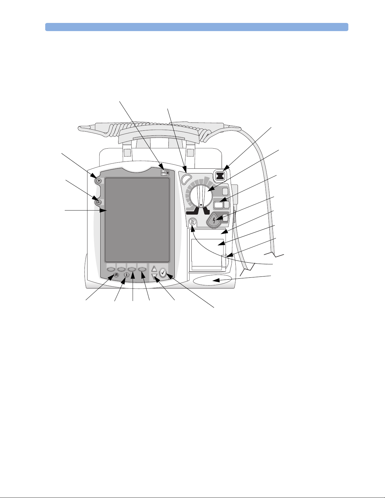
Figure 1 Front view
External Power Indicator
Synchronized Cardioversion
(Sync) button
Ready For Use (RFU)
Indicator
Mark Event
button
Lead Select
button
Display
Alarm Pause button
Event Summary
button
Soft keys (4 total)
c
n
y
S
120
b
b
i
i
100
f
f
e
e
70
D
D
l
l
a
a
50
u
u
n
n
a
a
30
M
M
20
15
1-10
n
O
P
acer
O
ff
M
onitor
Navigation buttons
A
dult
D
ose
150
170
200
S
elect
E
nergy
1
C
harge
O
n
AED
2
S
hock
3
Menu Select button
Therapy Knob
CHARGE button
SHOCK button
Printer
Printer door
Printer door
latch
Print button
Speaker
3
Page 14
1 Introduction Tour of the Device
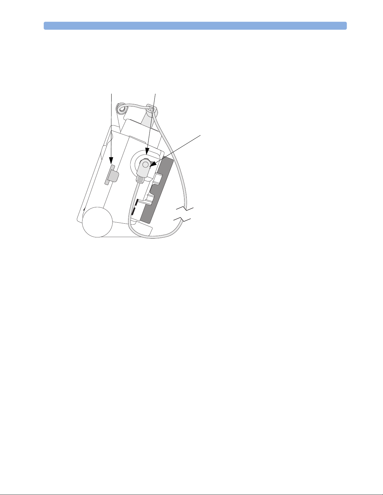
Right Side
Figure 2 Right side view
Data Card
Therapy port (behind connector)
Therapy connector
4
Page 15
Tour of the Device 1 Introduction
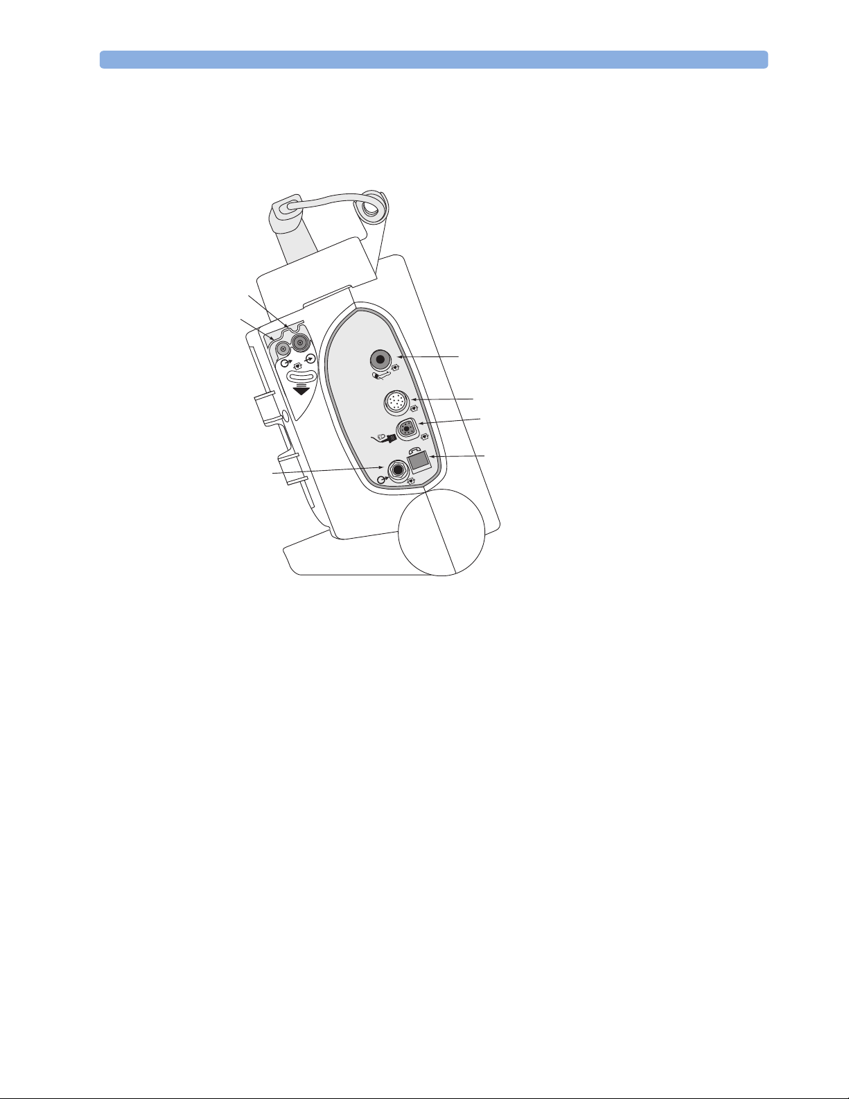
Left Side
Figure 3 Left side view
CO2 Inlet Port
CO2 Outlet Port
ECG Out (Sync)
Jack
2
CO
™
m
a
e
r
t
s
o
r
c
i
M
1
NBP Port
2
ECG Port
ECG
SpO2 Port
RJ11 Telephone
Jack
ECG
5
Page 16
1 Introduction Tour of the Device
t
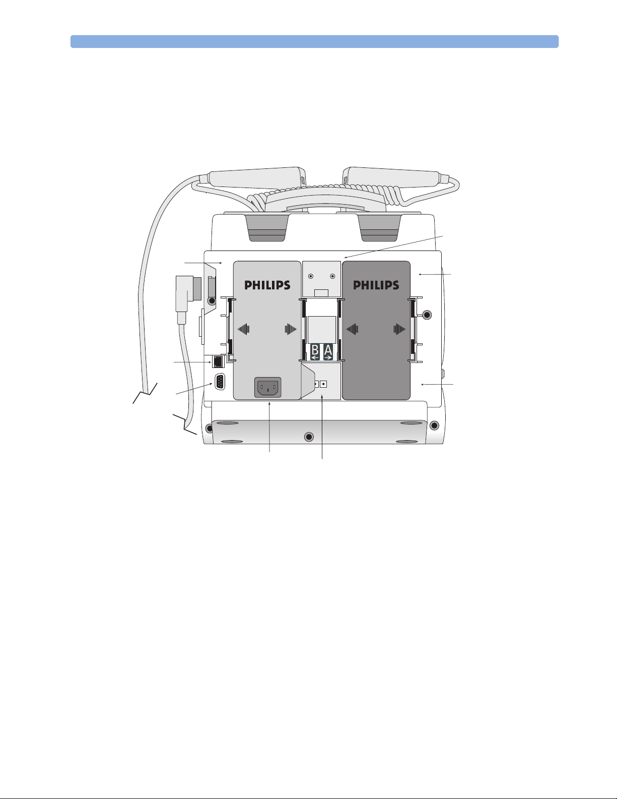
Rear
Figure 4 Rear view
Bed Rail Hook Moun
Battery/AC
Compartment B
Battery
Compartment A
LAN Connection
RS 232 Serial Port
AC Power Module
NOTE The LAN port is for factory use only.
Battery
DC Power Input
6
Page 17
Tour of the Device 1 Introduction
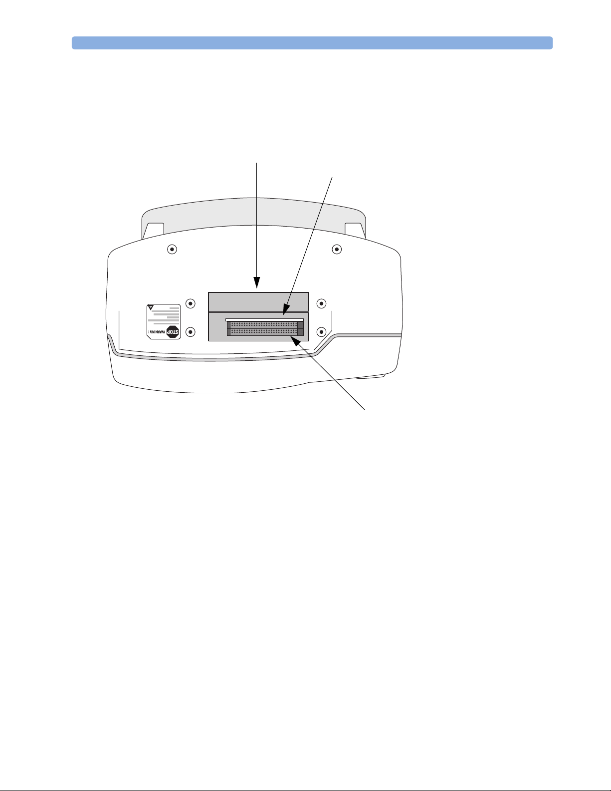
Top
Figure 5 Top view.
Top access panel
PCMCIA card slots
Internal memory card slot
7
Page 18

1 Introduction General Service Information
General Service Information
Keep the following points in mind when servicing this product.
Installation
The HeartStart MRx does not require installation. The Instructions for Use describes the setup required
before placing the device into service, as well as configuration options. All setup activities are designed
to be performed by personnel trained in the proper operation of the product. To obtain a copy of the
Instructions for Use and other MRx documentation go to:
www.medical.philips.com/goto/productdocumentation.
Display Menus
To display a menu, press the Menu Select button. Then use the up or down Navigation
buttons to scroll through the available choices until the desired selection is highlighted. To activate the
selection, press the Menu Select button. Press Exit to close the menu without activating a selection.
Passwords
In order to access different modes within the monitor/defibrillator, a password is required. The
passwords are listed below:
Upgrades
• Service Mode: 27689
• Configuration Mode: 387466
Upgrades are available to add specific functionality to the device after purchase. These upgrades are:
• M3530A SpO
• M3531A NBP
• M3532A CO
• M3533A Pacing
• M3534A 12-Lead
Option B02 - 12-lead acquisition
Option B03 - 12-lead transmission
Option B04 - 75 mm printer
• M4760A Handle and Cap Plate
• M5527A External paddles
• M4765A Hardware Upgrade Option B01 - Version B hardware that supports 12-lead transmission
Consult your sales representative, dealer, or distributor for the latest details.
2
2
Preventive Maintenance
Preventive maintenance and periodic operational checks are intended to be performed by the user.
Both topics are covered in the Maintenance chapter of the Instructions for Use.
The Maintenance chapter of this manual provides procedures for the CO
procedures, which are intended to be performed by qualified service personnel.
8
and NBP calibration
2
Page 19

General Service Information 1 Introduction
Repair Philosophy
Monitor/Defibrillator
The repair philosophy of the HeartStart MRx is subassembly replacement. Examples of subassemblies
are the printer, the Processor Printed Circuit Assembly (PCA), Therapy PCA, and selected connectors
and other items. Repairs that involve replacing components on a PCA are not supported.
CAUTION Individual component replacement should not be attempted. Component level repair is inadvisable
due to the extensive use of surface mount technology and the high parts-density on the circuit boards.
Unauthorized component replacement can impair performance of the HeartStart MRx.
WARNING Remove all power sources (AC, battery, DC) before opening the device. Failure to do so may allow the
device to charge without warning and could result in serious injury or death.
Batteries
The M3538A Lithium Ion battery is rechargeable. The battery periodically requires a calibration. At
the end of the battery’s useful life, it should be discarded and replaced. Refer to the Instructions for Use
for additional information.
For information on ordering replacements, see "Ordering Supplies and Accessories" on page 212.
WARNING Never crush, penetrate or attempt to open lithium ion batteries. Never incinerate lithium ion batteries.
High case temperatures resulting from abuse of the battery could cause physical injury. The electrolyte
is highly flammable. Rupture of the battery pack may cause venting and flame.
CAUTION Due to their high energy density, lithium ion batteries can deliver significant power. Use care when
working with or testing lithium ion batteries. Do not short circuit the terminals.
9
Page 20

1 Introduction Accessing Service Mode
Accessing Service Mode
CAUTION Be sure that the monitor/defibrillator is not connected to a patient when performing any function in
Service Mode.
NOTE Make sure that you insert a battery charged to at least 20% into the device or connect external power
when you are performing functions in Service Mode.
To access Service Mode:
1. Turn the Therapy Knob to Monitor.
2. Press the Menu Select button to display the Main menu.
3. Select Other.
4. From the Other menu select Service.
The message “Leaving Normal Operating Mode. Patient Monitoring is Off. To return to Normal
Operating Mode, press the Exit Softkey.” appears.
5. Press the Menu Select button to acknowledge the message.
You are prompted to enter a password.
6. Enter the password (27689) by scrolling through the list until the desired number is highlighted.
7. Press the Menu Select button to activate each selection.
8. Select Done when you have entered all of the numbers.
10
Page 21

Accessing Service Mode 1 Introduction
The Service Mode Main menu is displayed, as shown in Figure 6.
Figure 6 Service Mode Main Menu
02 Mar 2003 10:52
Service
Exit
Service
.
MAIN
Service
Operational Check
Status Log
NBP
CO2
Controls
Printer
Device Info
Software Upgrade
Navigating in Service Mode
Service Mode uses the same navigation controls as normal operating mode:
• To select a menu item, use the Navigation buttons to highlight your choice, then select that choice
by pressing the Menu Select button.
• To exit Service Mode and return to clinical mode, press the [Exit Service] soft key.
• To return to the Service Mode Main menu from any service screen press the [Main Service]
soft key.
NOTE The device’s default configuration settings are restored when you return to clinical mode after exiting
Service Mode.
11
Page 22

1 Introduction Accessing Service Mode
Service Mode Functions
You can perform a variety of service related activities from Service Mode, as follows:
• Run an Operational Check - See “Operational Check” on page 39.
• View, print and clear the Status log - See “Status Log Errors” on page 55.
• Perform maintenance on the NBP module - See “Checking the NBP Module” on page 19.
• Perform maintenance on the CO
• Run the Controls test - See “Controls Test” on page 193.
• Run the Printer test - See “Printer Test” on page 194.
• View information about the device, such as model number, serial number, options enabled on the
device, and the device’s language - See “Device Info” on page 13. You also use the Device Info menu
to enter the serial number and to enable options on the device after a Processor PCA repair. See
“Entering the Serial Number and Enabling Options” on page 128 for more information.
NOTE You can print detailed information on board and module levels through the Print Device Info option,
available in normal operating mode. See “Printing the Device Information” on page 16.
• Install software and change the device’s language using the Software Support Tool - See “Software
Support Tool” on page 13.
module - See “Checking the CO2 Module” on page 23.
2
12
Page 23

Accessing Service Mode 1 Introduction
Device Info
To view information about the device:
1. From the Service Mode Main menu, select Device Info.
Figure 7 Device Info Screen
02 Mar 2003 10:52
Service
Model Number: M3536A
Serial Number: US00100320
Options: SpO2, CO2, NBP
Language: American English
.
DEVICE INFO
Main
Service
Software Support Tool
To install software onto the device or to change the device’s language:
1. Be sure an AC power module or battery charged to at least 20% is in place.
2. Insert the Software Support Tool into the data card slot.
3. From the Service Mode Main menu, select Software Upgrade.
4. Select the appropriate product version.
5. Press the [Upgrade] soft key.
The software is installed on the device. This process takes a few minutes. While the software is
being updated, progress messages are displayed and the [Main Service] soft key is disabled.
MENU
13
Page 24

1 Introduction Accessing Service Mode
NOTE
Be careful not to interrupt the software installation process by removing the power source or turning
the device off.
Figure 8 Software Upgrade Screen
02 Mar 2003 10:52
Service SOFTWARE UPGRADE
HeartStart MRx Version B.04.00 Upgrade: American English
.
Main
Service
6. When the software or language installation process is complete, turn the device off and on.
7. Run an Operational Check.
8. Review the Operational Check results to ensure all tests have passed.
See “Operational Check” on page 39.
9. Print the Device Info to ensure the product version or language is correct.
See “Printing the Device Information” on page 16.
Prev
Item
Next
Item Upgrade
14
Page 25
Accessing Service Mode 1 Introduction
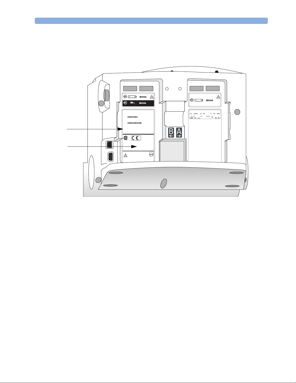
10. Affix the appropriate label found in the Software Support Tool kit to battery compartment B, as
show in Figure 9. Additionally, make sure that the customer has the Instructions for Use (found
on the User Documentation CD) that matches the product version.
Figure 9 Rear case labels
Primary label
Product Version
label
B2.04.00
NOTE The label that you apply to the device is in the format Xx.xx. This is functionally equivalent to the X.xx
Product Version that appears on the Device Info and Software Upgrade screens and the printed device
information report. For example, product version B2.04 is functionally equivalent to B.04.
15
Page 26

1 Introduction Other Resources
Printing the Device Information
You can print detailed information on product versions, and board and module levels from the Print
Device Info menu option. This option is available from the Other menu in clinical modes.
To print the device information:
1. Be sure a battery charged to at least 20% is in place, or that external power is connected.
2. Turn the Therapy Knob to Monitor.
3. Press the Menu Select button to access the Main menu.
4. From the Main menu, select Other.
5. From the Other menu, select Print Device Info.
Detailed information about the device is printed.
Other Resources
For additional information on the HeartStart MRx, refer to the following Learning Products:
• HeartStart MRx Instructions for Use (M3535-91900)
• HeartStart MRx Service Training Video (M3535-89300 NTSC, M3535-89310 PAL)
• HeartStart MRx Lithium Ion Battery Characteristics and Care Application Note (M3535-91930)
Other documentation can be found on the Philips website at:
www.medical.philips.com/goto/productdocumentation.
16
Page 27

This chapter describes how to perform routine maintenance on the HeartStart MRx
monitor/defibrillator.
Overview
Most routine maintenance is performed by the user. This includes:
• Performing operational checks
• Replacing paper
• Charging and maintaining the lithium ion battery
•Cleaning
2
2Maintenance
Refer to the Instructions for Use for detailed information on these maintenance procedures.
Service personnel are responsible for the following routine maintenance:
• Yearly calibration (or every 10,000 cycles) of the Noninvasive Blood Pressure (NBP) module
• Yearly calibration (or every 4000 hours) of the End-tidal Carbon Dioxide (EtCO
This chapter provides the following information:
To p ic Pa ge
Maintenance Tools and Equipment 18
Checking the NBP Module 19
Checking the CO
Module 23
2
) module
2
17
Page 28

2Maintenance Maintenance Tools and Equipment
Maintenance Tools and Equipment
You will need the following equipment to perform the yearly calibration procedures:
• Password to access Service Mode (27689)
•NBP
– manometer
– expansion chamber (volume 250 ml +/- 10%) or an NBP cuff can be used
NOTE If you are using an NBP cuff, make sure it is wrapped around a solid object.
•CO
NOTE In addition to the items listed above, the calibration procedures require tubing and connectors typically
found in a biomedical engineering shop.
2
– calibration gases and regulator
cal 1 gas 15210-64010 (5% CO
cal 2 gas 15210-64020 (10% CO
cal gas flow regulator M2267A
– electronic flowmeter, M1026-60144
– Gas calibration equipment
cal tube 13907A
FilterLine set, M1920A
– local barometric pressure rating or reading received from a reliable local source (airport, regional
weather station, or hospital weather station) which is located at the same altitude as the hospital
or EMS service.
– calculator
)
2
)
2
18
Page 29

Checking the NBP Module 2 Maintenance
Checking the NBP Module
NBP
These instructions describe how to test the NBP measurement function. A complete test consists of the
following activities, which are described in detail in this chapter.
NBP Check Page
Setup
Setup
Check the status displays
Test the accuracy
Test for leaks
Tes t t he l i ne a r it y
Calibrate the NBP Measurement
Run an Operational Check
Each of the procedures assumes the monitor/defibrillator, the manometer, and the expansion chamber
are still set up as they were at the end of the previous test.
If all results are as described, the device passes that portion of the test. Return to the Service Mode
Main menu by pressing the [Main Service] soft key.
If there is any failure, begin troubleshooting and repairing the device as needed. See
“Troubleshooting” on page 33.
1 Access the Service Mode Main menu as described in “Accessing Service Mode” on page 10.
2 From the Service Mode Main menu, select NBP.
The NBP Service screen is displayed.
19
20
21
21
22
22
22
19
Page 30

2Maintenance Checking the NBP Module
NOTE
You will hear a high-pitch tone when you access the NBP Service screen - this is normal operation.
Figure 10 NBP Service Screen
02 May 2003 10:52
Service
Cycle Counter: 50,010
Last Calibration: 2 May 2004
Pressure In Cuff: 23 mmHg
.
NBP
Replacement recommended
Calibration recommended
Main
Service
Check the status displays
1. Check the cycle counter.
Check the number of measurement cycles shown on the screen. If the NBP module has executed
more then 50,000 cycles, replacement is recommended. See “NBP Module” on page 160 for
instructions on replacing the NBP module.
Following replacement, run the required Performance Verification and Safety Tests (see “Required
Testing Levels” on page 180).
2. Check the calibration status.
If the screen indicates that calibration is recommended, perform all of the actions described in this
chapter, beginning with "Test the accuracy".
The calibration status is automatically reset at the successful completion of a calibration.
20
Calibrate
Page 31

Checking the NBP Module 2 Maintenance
NBP Safety Timeout
Do not keep the cuff pressurized for more than 3 minutes. The NBP module times out if the pressure
is greater than 5mmHg for 180 seconds. The valve opens and the pressure drops. To reset the module,
exit Service Mode and press the [Start NBP] soft key. The inop “Cuff not deflated” is displayed.
Access the NBP Service screen again to start the calibration.
Test the accuracy
1 Connect the NBP tubing to the NBP port on the monitor/defibrillator, and connect the test
manometer and expansion chamber to the tubing. See Figure 11.
Figure 11 NBP Test Setup
Expansion Chamber
2 Pressurize the expansion chamber to approximately 280 mmHg.
3 When the pressure stabilizes, compare the displayed pressure reading to the pressure indicated by
4 If the difference between the manometer and the displayed pressure is >+ 2mmHg, perform the
Test for leaks
1 Pressurize the expansion chamber to approximately 280 mmHg.
Tu b i n g
To N B P p o r t
1
2
ECG
ECG
Manometer
the manometer.
steps in “Calibrate the NBP Measurement” on page 22.
c
n
y
S
dult
A
e
s
o
D
0
12
150
n
0
10
0
O
17
b
0
i
7
f
0
0
2
e
D
0
5
t
c
e
l
e
S
y
g
r
e
1
n
E
0
4
0
3
e
g
r
a
h
C
0
2
10
-
2
2
r
e
c
a
D
P
E
A
k
c
ho
S
n
O
ff
O
r
nito
o
M
3
2 Watch the displayed pressure for 60 seconds.
3 At the end of this 60 seconds record the pressure drop. Any pressure drop observed should be
<
6 mmHg.
4 If the pressure decreases by more than 6 mmHg, there is a leak. Replace the NBP tubing and cuff
and try the leakage test again. If the pressure still decreases by more than 6 mmHg, begin
troubleshooting and repairing the device as needed.
5 Release the pressure in the cuff before proceeding to the next test to avoid the safety timeout.
21
Page 32

2Maintenance Checking the NBP Module
Test the linearity
1 Pressurize the expansion chamber to increase pressure to approximately 150 mmHg.
2 When the pressure is stabilized, compare the displayed pressure reading to the pressure indicated
by the manometer.
If the difference between the manometer and the displayed pressure is >±2mmHg, perform the
steps in "Calibrate the NBP Measurement". Then repeat this linearity test.
Calibrate the NBP Measurement
NOTE If the error message “Calibration failed. Check that the pressure applied is correct. Please restart
calibration.” appears after entering either calibration point, re-start the calibration.
Pressing the [Calibrate] soft key starts the calibration process. You must complete the calibration
process within three minutes or the NBP module times out and will be out of calibration.
1 Press the [Calibrate] soft key.
The message “Apply 0 mmHg. Select Next when ready” is displayed.
2 Release all of the pressure in the expansion chamber so that the manometer reads 0 mmHg.
3 Press the [Next] soft key.
The message “Apply 250 mmHg. Select Next when ready” is displayed.
4 Increase the pressure so that the manometer reads 250 mmHg.
5 Press the [Next] soft key.
If the calibration is successful, the message “Calibration complete. Please perform the accuracy and
leakage tests to check the results.” is displayed. After several seconds the message clears and the NBP
Service screen is displayed.
Run an Operational Check
You must run an operational check after calibrating the NBP module in order for the calibration status
to get updated. See “Operational Check” on page 39 for instructions.
22
Page 33

Checking the CO2 Module 2 Maintenance
Checking the CO2 Module
CO
2
These instructions describe how to test the CO2 module. The CO2 tests are as follows:
Check Page
CO
2
Setup 23
Check the Status Display 24
Ambient Pressure 25
Leakage Check 26
Pump Check 27
Flow Rate Check 28
Noise Check 28
Calibration Check 29
CO
Calibration 30
2
Run an Operational Check 31
Setup
Each of the tests assumes the device and the test equipment are still set up as they were at the end of the
previous test.
If all results are as described, the device passes that portion of the test. Return to the Service Mode
Main menu by pressing the [Main Service] soft key.
If there is any failure, begin troubleshooting and repairing the device as needed. See
“Troubleshooting” on page 33 for more information.
1 Access the Service Mode Main menu as described in “Accessing Service Mode” on page 10.
2 From the Service Mode Main menu, select CO
The pump starts when you access the CO
.
2
Service screen.
2
23
Page 34

2Maintenance Checking the CO2 Module
The CO2 Service screen is displayed, as shown in Figure 12.
Figure 12 CO
Service Screen
2
02 Mar 2003 10:52
CO2 Sensor Warmup
Service
.
CO2
CO2 Operating Hours: 15,010 hours
Last Calibration: 9 Jun 2002
Ambient Pressure: 756 mmHg
Cell Pressure: 756 mmHg
Replacement recommended
Main
Service
Check the Status Display
1. Check the CO2 Operating Hours.
You are directed to replace the CO
hours is more than 15,000 the message “Replacement recommended” is displayed. See “CO
Module” on page 162 for instructions on replacing the CO
2. Check calibration status.
Displays the date of the last calibration. The CO
4000 hours. If more than one year has passed or the module has operated more than 4000 hours
since the last calibration, the message “Calibration recommended” is displayed. Perform all of the
actions described in this section, beginning with “Ambient Pressure.”
CO2
Ambient Pressure
Leakage Check
Pump Check
Flow Rate Check
Noise Check
Calibration Check
Exit
module after 15,000 hours of operating time. If the number of
2
2
module.
2
module should be calibrated every year or after
2
24
Page 35

Checking the CO2 Module 2 Maintenance
3. Check the ambient and cell pressure.
Obtain a reliable measurement of local barometric pressure (reference value). This is typically
available from a local airport, weather station, or the internet. Be sure the reading is taken at the
same altitude as the monitor/defibrillator is at now. Check that the monitor/defibrillator’s internal
setting of ambient atmospheric pressure (barometric pressure) is within +
reference value. If the ambient pressure is not within +
12 mmHg of the reference value, adjust it
through the Ambient Pressure menu. If the ambient pressure is within +
12 mmHg of the
12 mmHg of the reference
value, proceed with the Leakage check.
Ambient Pressure
This menu enables you to adjust the ambient pressure setting of the monitor/defibrillator.
1 If the ambient pressure is not within + 12 mmHg of the reference value, select Ambient Pressure
from the CO
2 Use the Navigation buttons to enter the barometric pressure reference value.
The displayed ambient pressure is updated to the reference value.
Service menu.
2
25
Page 36

2Maintenance Checking the CO2 Module
Leakage Check
The leakage check consists of two parts:
1 Check of the internal tubing between the pump outlet and the CO
Outlet port on the
2
monitor/defibrillator (device outlet). This test is done by pressurizing the outlet line between the
pump and the outlet port.
2 Check of the internal tubing between the pump inlet and the FilterLine inlet. This test is done by
pulling a vacuum on the inlet line between the inlet fitting and the pump.
These procedures are described in the following sections.
Outlet leakage
To perform Part 1 of the CO2 Leakage check:
1 From the CO
Service menu, select Leakage Check.
2
2 Set up the flowmeter and the MRx.
a. Connect the FilterLine to the monitor/defibrillator CO2 Inlet port.
b. Connect tubing from the flowmeter outlet to the FilterLine.
Figure 13 CO
Outlet Leakage Check Setup
2
1
2
26
3 Follow the instructions on the screen to perform Part 1 of the Leakage check.
4 The reading on the flowmeter should decrease to between 0 and 4 ml/min.
If this reading is correct, proceed to the second part of the leakage test (the Inlet Leakage) by
pressing the [Proceed] soft key.
If this reading is incorrect (>4 ml/min. flow) it indicates a leak in the line between the pump outlet
and the CO
Outlet port. Begin troubleshooting and repairing the device as needed. See
2
“Troubleshooting” on page 33.
Page 37

Checking the CO2 Module 2 Maintenance
Inlet leakage
To perform Part 2 of the CO2 Leakage check:
1 Set up the flowmeter and the MRx.
a. Leave the FilterLine connected to the monitor/defibrillator CO
Inlet port.
2
b. Disconnect the FilterLine from the flowmeter outlet.
c. Connect the tubing from the flowmeter inlet to the monitor/defibrillator CO
Outlet port.
2
Figure 14 CO2 Inlet Leakage Check Setup
1
2
2 Follow the instructions on the screen to perform Part 2 of the Leakage check.
3 The reading on the flowmeter should decrease to between 0 and 4 ml/min.
If this reading is incorrect (>4 ml/min. flow) it indicates a leak in the line between the FilterLine
inlet and the pump inlet. Begin troubleshooting and repairing the device as needed. See
“Troubleshooting” on page 33.
Pump Check
This test checks the ‘strength’ of the pump by occluding the inlet and measuring how deep a vacuum
the pump can pull.
NOTE It is important these tests be conducted in this order. For example, if you perform the Pump check and
there’s a leak you haven’t found because you didn’t perform the leak tests, it may appear that the device
has a faulty pump when in fact it’s a loose tubing connection.
1 From the CO
2 Follow the instructions on the screen to perform the Pump check.
3 The difference between the cell pressure displayed and the ambient pressure should be more than
120 mmHg.
If the pressure reading is correct (difference >120 mmHg), the device passes the pump test.
If the pressure reading is incorrect, it indicates the pump is defective (regardless of the number of
hours it has run) and the CO
Service menu, select Pump Check.
2
module must be replaced. See “CO2 Module” on page 162.
2
27
Page 38

2Maintenance Checking the CO2 Module
Flow Rate Check
1 From the CO
2 Follow the instructions on the screen to perform the Flow Rate check.
NOTE Be sure there are no kinks, pinches, or obstructions in any of the tubing - this can create a restriction
that will diminish the flow rate and cause a false failure of this test.
3 If the flow rate is within the tolerance limit (50 ml/min ±7.5 ml/min), the test passes.
If the flow rate is not within the tolerance limit, proceed to Step 4 to calibrate the flow rate.
4 Use the Navigation buttons to increase and decrease the flow until it is as close as possible to 50 ml
per minute as indicated on the flowmeter gauge.
5 When you are satisfied that the flow is set as close as possible to 50 ml, press the [Store Flow]
soft key to confirm the setting. If the adjusted flow is not stored within 60 seconds of the
adjustment, the old flow setting is restored.
Service menu, select Flow Rate Check.
2
NOTE If the flow cannot be adjusted to within tolerance, the CO
Module” on page 162.
Noise Check
This test looks for noise on the CO2 signal due to deterioration of the IR source.
1 From the CO
2 Set up the calibration gas as shown in Figure 15.
a. Connect the 5% calibration gas to the CO2 Inlet port.
b. Turn on the gas.
Figure 15 CO
M2267A
15210-64020
10%
15210-64010
5%
Service menu, select Noise Check.
2
Noise and Calibration Check Setup
2
M1920A
module must be replaced. See “CO2
2
1
2
28
13907A
End open to atmosphere
3 Follow the instructions on the screen to perform the Noise check.
4 Wait until the displayed CO
value is stable. Check the noise index reading.
2
Page 39

Checking the CO2 Module 2 Maintenance
5
If the noise index exceeds 3 mmHg, the CO2 module must be replaced. See “CO2 Module” on
page 162.
Calibration Check
This tests the accuracy of the CO2 measurement and, if needed, adjusts the measurement to meet
specifications.
1 The monitor/defibrillator must be operating for at least 20 minutes prior to starting this test with
the FilterLine connected to the CO
2 From the CO
3 The CO
5% Calibration Check
Set up the calibration gas as shown in Figure 15.
4
Service menu, select Calibration Check.
2
Calibration screen is displayed,
2
a. Connect the 5% calibration gas to the CO2 Inlet port.
b. Turn on the gas.
Inlet port.
2
5 Wait until the displayed CO
6 Calculate the expected CO
value is stable.
2
reading, which depends on both the gas concentration you are using
2
(typically 5.0%) and the ambient pressure. Calculate as follows:
[concentration of cal gas] X [ambient pressure] = expected CO2 value
For example:
[0.05] X [736 mmHg] = 36.8 mmHg
7 Calculate the allowable tolerance, which is ±5% of the expected reading. Calculate as follows:
[±0.05] X [expected CO
value]] = ±[tolerance] mmHg
2
example:
[±0.05] X [36.8 mmHg] = ±1.8 mmHg
In this example, the reading displayed with 5% cal gas must be 36.8 mmHg ±1.8 mmHg, or
between 35.0 mmHg and 38.6 mmHg.
8 Compare the displayed CO
value to the allowable range of values.
2
If the displayed value falls within the allowable range, proceed to the 10% Calibration Check
section below.
If the displayed value does not fall within the allowable range, the CO
needs to be calibrated. Perform the steps under “CO
Calibration” on page 30, then begin again at
2
measurement module
2
step 1.
29
Page 40

2Maintenance Checking the CO2 Module
10% Calibration Check
Disconnect the 5% gas (and regulator, if needed) and connect the 10% gas.
1
2 Turn on the gas.
3 Wait until the displayed CO
4 Calculate the expected CO
value is stable.
2
reading, which depends on both the gas concentration you are using
2
(typically 10.0%) and the ambient pressure. Calculate as follows:
[concentration of cal gas] X [ambient pressure] = expected CO2 value
example:
[0.10] X [736 mmHg] = 73.6 mmHg
5 Calculate the allowable tolerance, which is ±7% of the expected reading. Calculate as follows:
[±0.07] X [expected CO
value]]= ±[tolerance] mmHg
2
example:
[±0.07] X [73.6 mmHg] = ±5.2 mmHg
In this example, the reading displayed with 10% cal gas must be 73.6 mmHg ±5.2 mmHg, or
between 68.4 mmHg and 78.8 mmHg.
6 Compare the displayed CO
7 Return to the CO
CO2 Calibration
If you haven’t already done so, perform the following three steps before proceeding with the calibration.
1 The monitor/defibrillator must be operating and a FilterLine connected to the CO
2 From the CO
3 The CO
value to the allowable range of values.
2
If the displayed value falls within the allowable range, the device has passed its accuracy test.
If the displayed value does not fall within the allowable range, the CO
needs to be calibrated. Perform the steps under “CO
Calibration” on page 30, then begin again at
2
measurement module
2
step 1.
Service screen by pressing the [Done] soft key.
2
Inlet port for
2
at least 20 minutes prior to starting this test.
Service menu, select Calibration Check and press the Menu Select button.
2
Calibration screen is displayed. Wait until the display indicates the autozero is finished
2
before proceeding.
30
Page 41

Checking the CO2 Module 2 Maintenance
Calibration
Connect the 5% calibration gas (and regulator, if needed) to the CO2 Inlet port. Turn on the gas.
4
5 Wait until the displayed CO
6 Press the [Calibrate] soft key.
7 The screen prompts you for the value of cal gas being used. Acceptable values are from 4% to 6%.
value is stable.
2
The recommended value is 5%, which is the default.
8 Using the Navigation buttons, set the correct cal gas value, then press the Menu Select button.
9 When you have selected the correct cal gas value, the monitor/defibrillator begins an auto
calibration sequence, and the screen displays the message "CO
calibration in progress". Do not
2
remove the gas until the monitor/defibrillator is finished as indicated by the screen prompts.
Calibration Verification
If it is not already connected, connect the 5% calibration gas (and regulator, if needed) to the CO2
10
Inlet port. Turn on the gas.
11 Wait until the displayed CO
12 Check the displayed CO
value is stable.
2
value against the expected value calculated earlier. The displayed value
2
should match the expected value within the tolerance calculated earlier.
13 Disconnect the 5% gas and connect the 10% gas.
14 Wait until the displayed CO
15 Check the displayed CO
value is stable.
2
value against the expected value calculated earlier. The displayed value
2
should match the expected value within the tolerance calculated earlier.
If both the 5% and 10% values are correct, the device has been successfully calibrated.
If either value is not within tolerance, repeat the calibration beginning at step 1. If the device fails
the Calibration Verification a second time, replace the CO
page 162.
Run an Operational Check
You must run an operational check after calibrating the CO2 module in order for the calibration status
to get updated. See “Operational Check” on page 39 for instructions.
module. See “CO2 Module” on
2
31
Page 42

Page 43

This chapter describes how to troubleshoot the HeartStart MRx monitor/defibrillator.
Overview
Here are the topics covered in this chapter:
To p ic Pa ge
Troubleshooting Tools and Equipment 34
Obtaining Replacement Parts 34
Ready For Use Indicator 35
Automated Tests 36
Operational Check 39
Service Mode Tests 44
Troubleshooting Methodology 45
Troubleshooting Flowcharts 47
Troubleshooting Tables 53
3
3Troubleshooting
33
Page 44

3 Troubleshooting Troubleshooting Tools and Equipment
Troubleshooting Tools and Equipment
You need the following tools and equipment:
• Defibrillator Discharge Tool (M2475-69573) — Used to discharge the defibrillator capacitor.
• 50 ohm defibrillator test load, grey plug connector (M3725A)
• 50 ohm defibrillator test load, white barrel connector (M1781A)
Obtaining Replacement Parts
See “Parts and Accessories” on page 211 for details on replacement parts.
34
Page 45

Ready For Use Indicator 3 Troubleshooting
Ready For Use Indicator
The Ready For Use (RFU) indicator, located on the upper right corner of the device, reports the status
of critical functions of the device as determined by the Automated tests. These Automated tests run
periodically while the device is turned off (but has a power source) and check the following critical
functions of the device:
• defibrillation and cardioversion
•pacing
• pads/paddles ECG
• 3-lead/5-lead/12-lead ECG
• battery
The RFU indicator also reports failures in critical functions detected at run time, during an
Operational Check, and during Service Mode tests. Always check the RFU indicator when
troubleshooting the device.
Automated test failures of non-critical components (such as the NBP, SpO
modules) are not reflected in the RFU indicator, but are reported through inops when the device is
turned on.
The RFU indicator displays the status of the device using the following definitions.
Table 1 RFU Indicator Status
RFU Status Meaning Required Action
Blinking black hourglass Shock, pacing, and ECG functions are
ready for use and sufficient battery power
is available.
Blinking red “X” with or
without a periodic chirp
Solid red “X” and a
periodic chirp
Solid red “X” without a
periodic chirp
Low battery or no battery. The device
can be used but run time is limited.
Chirping indicates the battery is not
being charged. No chirping indicates the
battery is being charged.
A failure has been detected that prevents
the delivery of a shock, pacing, or ECG
acquisition.
No power, or device failure (cannot turn
on).
None
Charge the battery as soon as possible and/or
replace the battery with a charged battery.
Charging may be done in the HeartStart MRx
by connecting to AC/DC power, or in a
Philips-approved battery support system.
Turn the Therapy Knob to Monitor. A message
describing the failure is displayed. Begin
troubleshooting, as described in
“Troubleshooting Methodology” on page 45.
Note: The device displays the message for the
first critical failure that is detected. To see
additional failures (if any) run an Operational
Check and check the status log.
Insert a charged battery or connect to AC/DC
power. Begin troubleshooting, as described in
“Troubleshooting Methodology” on page 45.
, CO2, and printer
2
NOTE The RFU indicator briefly displays a solid red “X” when initially turning on the device, switching
between clinical and non-clinical operating modes, and at the start of any Automated test.
35
Page 46

3 Troubleshooting Automated Tests
Automated Tests
The HeartStart MRx performs many maintenance activities independently, including three tests that
run automatically at regularly scheduled intervals while the device is off to assess operational
performance and alert you if a problem exists. Results of tests associated with critical functionality of
the device are reported through the Ready For Use indicator and the Automated Test Summary report.
Results are also reported through inop statements on the display when the HeartStart MRx is turned
on. Table 2 provides a brief explanation of the tests and lists the frequency with which each test is
performed.
Table 2 Automatic Self-Tests
Tes t Ty p e /Freq u en c y Description
Hourly Tests batteries, internal power supplies, and internal memory.
Daily, between 11:00 PM and
1:00 AM
Weekly (Sunday between 11:00
PM and 1:00 AM)
Tests batteries, internal power supplies, internal memory,
internal clock battery, defibrillation, pacing, ECG, SpO
EtCO
, NBP, and printer. The defibrillation test includes low
2
energy internal discharges. If a 3-, 5-, or 10-lead ECG cable is
attached, the cable is tested as well.
Performs a Daily Test plus delivers a high energy internal
discharge to exercise the entire defibrillation circuitry.
,
2
NOTE Automated tests do not test the therapy cables, paddles, buttons, audio, or the display. An ECG cable is
tested if connected at the time of the test.
Automated Test Summary
An Automated Test Summary (ATS), showing the results of recent tests, may be viewed or printed as
evidence that the HeartStart MRx is tested regularly. To run the ATS:
1 Turn the Therapy Knob to Monitor.
2 Press the Menu Select button.
3 Using the Navigation buttons, select Other and press the Menu Select button.
4 Select Operational Check and press the Menu Select button.
The message “Leaving Normal Operating Mode” appears to let you know that you are exiting from
clinical functionality of the device.
5 Using the Navigation buttons, select Auto Test Summary and press the Menu Select button.
The Automated Test Summary is displayed.
6 Press the [Print] soft key to print the report.
36
Page 47

Automated Tests 3 Troubleshooting
The report shows the results of the most recent hourly test, the daily tests that have run since the last
weekly test, and the last 53 weekly tests. Test results are reported, as described in Table 3.
Figure 16 Automated Test Summary Screen
02 Mar 2003 10:52
Automated Test Summary
1 02 Mar 03 10:45 Hourly Pass
2 02 Mar 03 2:00 Daily Fail/NC
2 02 Mar 03 2:00 Daily Fail/NC
3 01 Mar 03 2:00 Daily Pass
4 28 Feb 03 2:00 Daily Pass
5 27 Feb 03 2:00 Daily Pass
6 26 Feb 03 2:00 Daily Pass
7 25 Feb 03 2:00 Daily Pass
8 24 Feb 03 2:00 Weekly Pass
9 17 Feb 03 2:00 Weekly Pass
10 10 Feb 03 2:00 Weekly Pass
11 03 Feb 03 2:00 Weekly Pass
12 27 Jan 03 2:00 Weekly Pass
13 20 Jan 03 2:00 Weekly Pass
14 13 Jan 03 2:00 Weekly Pass
15 06 Jan 03 2:00 Weekly Pass
16 30 Dec 02 2:00 Weekly Pass
17 23 Dec 02 2:00 Weekly Pass
18 16 Dec 02 2:00 Weekly Pass
19 09 Dec 02 2:00 Weekly Pass
20 02 Dec 02 2:00 Weekly Pass
21 25 Nov 02 2:00 Weekly Pass
22 18 Nov 02 2:00 Weekly Pass
23 11 Nov 02 2:00 Weekly Pass
24 04 Nov 02 2:00 Weekly Pass
25 28 Oct 02 2:00 Weekly Pass
26 21 Oct 02 2:00 Weekly Pass
27 14 Oct 02 2:00 Weekly Pass
28 07 Oct 02 2:00 Weekly Pass
29 30 Sep 02 2:00 Weekly Pass
30 23 Sep 02 2:00 Weekly Pass
31 16 Sep 02 2:00 Weekly Pass
32 09 Sep 02 2:00 Weekly Pass
33 02 Sep 02 2:00 Weekly Pass
34 26 Aug 02 2:00 Weekly Pass
35 19 Aug 02 2:00 Weekly Pass
36 12 Aug 02 2:00 Weekly Pass
37 05 Aug 02 2:00 Weekly Pass
38 29 Jul 02 2:00 Weekly Pass
39 22 Jul 02 2:00 Weekly Pass
40 15 Jul 02 2:00 Weekly Pass
41 08 Jul 02 2:00 Weekly Pass
42 01 Jul 02 2:00 Weekly Pass
43 24 Jun 02 2:00 Weekly Pass
44 17 Jun 02 2:00 Weekly Pass
45 10 Jun 02 2:00 Weekly Pass
46 03 Jun 02 2:00 Weekly Pass
47 27 May 02 2:00 Weekly Pass
48 20 May 02 2:00 Weekly Pass
49 13 May 02 2:00 Weekly Pass
50 06 May 02 2:00 Weekly Pass
51 29 Apr 02 2:00 Weekly Pass
52 22 Apr 02 2:00 Weekly Pass
53 15 Apr 02 2:00 Weekly Pass
54 08 Apr 02 2:00 Weekly Pass
55 01 Apr 02 2:00 Weekly Pass
56 25 Mar 02 2:00 Weekly Pass
57 18 Mar 02 2:00 Weekly Pass
58 11 Mar 02 2:00 Weekly Pass
59 04 Mar 02 2:00 Weekly Pass
30 25 Feb 02 2:00 Weekly Pass
Exit
Summary Print
37
Page 48

3 Troubleshooting Automated Tests
Tab l e 3 ATS R e s u lt s
Result RFU
Definition Required Action
Indicator
Pass Hourglass All tests passed None
Fail/C Solid Red “X”
accompanied
by a chirp
Fail/NC Hourglass A non-critical failure was detected. Non-
Fail/BF Blinking “X” The battery is not charged to the
A critical failure was detected. Critical
failures impact life-saving functionality,
including defibrillation, pacing, and
ECG acquisition.
critical failures do not impact life-saving
functionality.
minimum level (20%), there is no battery
present, or a battery failure was detected.
Respond to the RFU indicator as described
in “Troubleshooting Flowcharts” on
page 47.
Press the [Exit Summary] soft key. An
inop statement indicating the failure is
displayed.You can also note the time of the
failed test, then check the Status log for
failures logged at approximately the time of
the test. Refer to the Troubleshooting
Tables in this chapter for the action to take.
The message will continue to display in all
modes until the problem is corrected.
(Refer to the Instructions for Use for a
complete set of user prompts and
messages,)
Charge the battery as soon as possible and/
or replace the battery with a charged
battery. Charging may be done in the
HeartStart MRx by connecting to AC/DC
power, or in a
support system.
Philips-approved battery
38
Page 49

Operational Check 3 Troubleshooting
Operational Check
Operational Checks should be performed at regular intervals to supplement the hourly, daily, and
weekly Automated Tests executed by the MRx. Automated Tests provide adequate assurance that the
device is in a functional state of readiness. Operational Checks supplement the Automated Tests by
verifying therapy cables, the ECG cable, paddles, audio, and display functionality, along with
replicating the Weekly test. Operational Checks also notify you if the battery, NBP module, or CO
module need calibration.
At completion of the Operational Check, the message “Operational Check Passed” is displayed if all of
the tests pass. If any test fails the message “Non-Critical Failure”, “Critical Failure”, or “Battery
Failure” is displayed, depending upon the severity of the failed functionality. You must fix the problem
and successfully run the Operational Check to clear the failure.
Keep in mind the following points about the Operational Check:
• The Operational Check runs the Defib test on battery power to reflect optimal operating conditions
for defibrillation. The device automatically disconnects AC/DC power.
• Perform the Defib Test for each type of patient Therapy cable used on the device (multifunction
defib pads, external or internal paddles). At the conclusion of the Defib Test, you can attach another
Therapy cable and repeat the test.
2
• The message “In Progress” is displayed as each test is run. The test result (pass or fail) is displayed at
the completion of each test. (See Table 4 on page 41 for a full explanation of each test.)
• Use the test results to troubleshoot and repair the device.
• Clear the Status log after all errors have been addressed and the Operational Check passes. See
“Status Log Errors” on page 55 for more information.
To run the Operational Check:
1 Insert a battery charged to at least 20%.
2 Attach a Pads or Paddles therapy cable.
3 Attach an ECG cable.
4 Turn the Therapy Knob to Monitor.
5 Press the Menu Select button.
6 Using the Navigation buttons, select Other and press the Menu Select button.
NOTE You can run Operational Check from the Other menu in Monitor Mode or from the Service Mode
Main menu - the Operational Check is the same in both modes. When you exit the Operational Check
from Service Mode, you are returned to Monitor Mode.
7 Select Operational Check and press the Menu Select button.
8 Select Run Operational Check and press the Menu Select button.
“Leaving Normal Operating Mode. Patient Monitoring is Off. To return to Normal Operating
Mode, press the Exit Softkey.” appears.
9 Press the Menu Select button to acknowledge the message.
10 Carefully read and respond to the Operational Check prompts for each test. Screen prompts are
accompanied by an audio prompt to alert you of a message that should be acknowledged before
proceeding with the rest of the Operational Check.
39
Page 50

3 Troubleshooting Operational Check
When a response is required, use the Navigation buttons to select your answer and the Menu Select
button to confirm your choice. Table 4 shows the tests, in the order in which they are performed,
explains the prompts that may appear, and describes the actions you should take (if any).
NOTE Options that are not on the device do not appear on the screen or printed report.
Figure 17 Operational Check Screen
02 Mar 2003 10:52
Operational Check
Model Number: M3535A
Serial Number: US00108360
Last Operational Check: 01 Mar 2003 9:35 Pass
Display Test: Pass
General System Test: Pass
Audio Test: Pass
Leads ECG Test: Pass/ECG Cable
Pads/Paddles ECG Test: Pass/Pads
Pacer Test: Pass
Defib Test: Pass/External Paddles
Pass/Internal Paddles
Pass/Pads
Battery Compartment A Test: Pass/Cal Recommended
Battery Compartment B Test: Pass
SpO2 Test: In Progress
NBP Test:
CO2 Test:
Printer Test:
In Progress
Exit
Op Check
WARNING Be sure to safely discharge internal and external paddles tested during the Operational Check, as
described in Table 4.
40
Page 51

Operational Check 3 Troubleshooting
Table 4 Operational Check Tests
Te s t Description Prompts Action
Display A test pattern is displayed; the
display is filled with black, then
white, then red from top to
bottom, then green from left to
right.
General System Tests internal clock battery,
power supply, and internal
memory card.
Audio The voice prompt,
Delivered
Leads ECG Tests leads ECG acquisition
and, if attached, the ECG cable.
The recommended practice is
to run the test with the ECG
cable attached.
Pads/Paddles ECG Checks ECG acquisition
through pad/paddles.
is annunciated.
No Shock
Did you see the test pattern
correctly?
None. None.
Did You Hear, “No Shock
Delivered?”
•
Connect ECG Cable, Cable
Connected
or Test Without
Cable
• Detach Leads, if the ECG
cable is connected to a patient
or the leads are shorted
together.
•
Disconnect ECG Cable, if the
test fails with the cable
connected.
Remove Paddles from Holders
Place Paddles in Holders
Use the navigation buttons to
respond Yes or No. Then press
the Menu Select button.
Use the navigation buttons to
respond Yes or No. Then press
the Menu Select button.
• Connect an ECG cable and
select “Cable Connected” or
“Test Without Cable”.
• Make sure the leads are not
attached to a patient, a
simulator, or touching each
other.
• Disconnect the ECG cable.
Note: If testing paddles, make
sure that they are secured in
their pockets. If the PCI LEDs
light, adjust the paddles in the
pockets. If the LEDs continue to
light, clean the paddle electrode
surfaces.
Remove the paddles from the
holders.
Place the paddles in the holders.
Pacer
(only runs if the option
is present)
Tests pacing functionality and
delivers a paced pulse into a 50
ohm test load.
Connect Pads/Paddles Cable,
Connect Therapy Cable
• Connect Pads Cable, if the
Pads cable is not detected.
• Attach Test Load, if a test load
is not detected.
Attach the Pads or Paddles cable
typically used.
• Connect the Pads cable to the
MRx, if prompted.
• Connect the test load to the
Pads cable, if prompted.
41
Page 52

3 Troubleshooting Operational Check
Table 4 Operational Check Tests (Continued)
Te s t Description Prompts Action
Defib Tests defibrillation circuitry and
delivers a shock through:
• pads, into a test load,
and/or
• external paddles, into the
MRx,
and/or
• internal paddles, into a load.
Depending on the cable
connected, as follows:
• If the Pads cable is attached,
you are prompted to,
Verify
Test Load is Attached and
Press the Charge Button
• If external paddles are
attached, you are prompted to,
.
Verify Paddles are in Holders
and Press the Charge Button
• If internal paddles are
attached, you are prompted to,
Respond to the prompt, as
follows:
• Check the test load is
attached and press the
Charge button.
• Make sure the paddles are
seated in their pockets and
press the Charge button.
.
• Apply the paddles to the load
and press the Charge button.
Apply Paddles to Load and
Press the Charge Button
• If no cable is attached, you are
prompted to,
.
Cable
Once charged the Shock button
lights and you are prompted to,
Connect Therapy
.
• Connect a Therapy cable.
Press the Shock button.
Press Shock or Press Shock
buttons on paddles
After the test completes using one
Therapy cable, you are prompted
to,
Run defib test again with a
different therapy cable? Yes/No
Battery A
Battery B
SpO
2
NBP Checks to see if the NBP
CO
2
Printer Runs a printer self test. None. None.
Checks the capacity and
calibration status of the
batteries in Compartments A
and B.
Checks the internal SpO2 PCA.
The SpO
module is functioning;
determines if it is due for
calibration.
Checks to see if the CO
module is functioning;
determines if it is due for
calibration.
cable is not tested.
2
2
Cal Recommended, if battery
calibration is required.
None. None.
None. None.
None. None.
.
Use the Navigation and Menu
Select buttons to respond.
Change the cable and select
to repeat the test for another
cable. You should repeat the test
for each cable used. Select
once all cables have been tested.
If prompted, calibrate the
battery. See the Instructions for
Use for details.
Yes,
No,
42
Page 53

Operational Check 3 Troubleshooting
Operational Check Report
The Operational Check takes only a short time to complete. When it is done, a report is printed, as
shown in Figure 18. The first part of the report lists test results. The second part lists checks to be
performed by the user.
Figure 18 Operational Check Report
Operational Check Report
Model Number: M3535A
Serial Number: USD00123456
Options: 12-Lead NBP SpO2 EtCO2 Pacer
Ver.: B.03.00
Current Operational Check:
DD Mon YYYY HH:MM:SS
Last Operational Check:
DD Mon YYYY HH: MM:SS: Pass/Fail
Qty/Check List:
___ Defibrillator Inspection ___ CO2 FilterLine
___ Cables/Connectors
___ Paddles/Pads
___ Monitoring Electrodes
___ Charged Batteries
___ AC/DC Power & Cord
___ Printer Paper
___ Data Card
___ SpO2 Sensor
___ NBP Cuffs & Tubing
Current Test Results:
Display Test: Pass
General System Test: Pass
Audio Test: Pass
Leads ECG Test: Pass/ECG Cable
Pads/Paddles ECG Test: Pass/Pads
Pacer Test: Pass
Defib Test: Pass/External Paddles
Battery Compartment A Test: Pass
Battery Compartment B Test: Pass
SpO2 Test: Pass
NBP Test: Pass
CO2 Test: Pass
Printer Test: Pass
Comments:
Inspected by:______________________
Press the [Print] soft key when the Operational Check is complete to print an additional copy of the
report.
43
Page 54

3 Troubleshooting Service Mode Tests
Operational Check Summary
The Operational Check summary lists the results from the last 60 operational checks.
To view the Operational Check summary:
1 Turn the Therapy Knob to Monitor (or Exit Service Mode, if applicable).
2 Press the Menu Select button.
3 Using the Navigation buttons, select Other and press the Menu Select button.
4 Select Operational Check and press the Menu Select button.
5 Select Op Check Summary and press the Menu Select button.
The message “Leaving Normal Operating Mode. Patient Monitoring is Off. To return to Normal
Operating Mode, press the Exit Softkey.” appears. The Operational Check Summary screen is
displayed.
6 Press the [Print] soft key to print the report.
Service Mode Tests
These tests include manual interaction on tests such as the display and controls. These tests help you to
isolate any problems with the device. See “Service Mode Tests” on page 192 for more information on
Service Mode tests.
44
Page 55

Troubleshooting Methodology 3 Troubleshooting
Troubleshooting Methodology
We recommend using the methodology described on the following pages to isolate and repair problems
with the HeartStart MRx.
1. Decontaminate the device using local decontamination procedures.
Refer to the Instructions for Use.
2. Check the Ready for Use (RFU) indicator.
See “Ready For Use Indicator” on page 35.
3. Perform a visual inspection.
Thoroughly examine the device and its cables and accessories. Refer to “Visual Inspection” on
page 191.
If no further troubleshooting is needed, proceed to Step 13 to repair the device. Otherwise,
continue with Step 4.
4. Turn on the device.
Failures and messages appear on the display when you turn on the monitor/defibrillator.
Continue with Step 5.
5. Check the status log.
The Status log includes entries for all errors logged during normal operating mode, Automated
tests, Service Mode tests, and Operational Checks. The error indicates the most likely module or
PCA that failed. (See "Status Log Errors" on page 55 for more information.)
Continue with Step 6.
6. Run the Operational Check.
The Operational Check tests the functionality of all PCAs and modules present on the device. For
example, if the HeartStart MRx is equipped with the Noninvasive Blood Pressure measurement,
the Operational Check performs a self-test on that module, and includes the results both on the
screen and on the printed report. The Operational Check results indicate the area of the device that
is experiencing problems. Use this information to troubleshoot and repair the device. See
“Operational Check” on page 39 for detailed instructions.
Continue with Step 7.
7. Check the Status log and the Automated Test summary.
Any errors that occur during the Operational Check are written to the Status log. Use these
messages to isolate the problem. The Automated Test summary lists the results of past hourly, daily,
and weekly tests and provides you with information on the device’s history.
If no further troubleshooting is needed, proceed to Step 13 to repair the device. Otherwise,
continue with Step 8.
45
Page 56

3 Troubleshooting Troubleshooting Methodology
8. Use the Troubleshooting tables to identify the problem.
Use the Troubleshooting tables to find information on messages and common troubleshooting
issues.
If no further troubleshooting is needed, proceed to Step 13 to repair the device. Otherwise,
continue with Step 9.
9. Interview the user. Gather the external components.
If possible, talk directly with the user who reported the problem. Identify what they were doing
when the problem occurred, and exactly what happened. What was on the display? Were any
sounds noticed? Were there operational problems?
If possible, obtain the cables, paddles, battery, etc., that were in use when the problem occurred
and use them in your evaluation.
If no further troubleshooting is needed, proceed to Step 13 to repair the device. Otherwise,
continue with Step 10.
10. Try to reproduce the problem.
Try to reproduce the problem using the Troubleshooting tables to identify the symptoms and
possible solutions and perform any repairs indicated, as in Step 13.
If the problem cannot be reproduced, an intermittent condition or operator error is likely. Check
the device’s repair history (Step 11.)
11. Examine the device’s repair history.
Some intermittent problems cannot be reproduced. If the device was returned before for the same
problem, replace the most likely subassembly.
12. Run the Service tests, if needed.
Use the tests available in Service Mode to focus in on possible causes. See“Service Mode Tests” on
page 192 for more information.
13. Repair any problems found.
Follow the procedures in the Repair chapter to replace defective parts or subassemblies. When the
repair is complete, continue with Step 14.
14. Verify the device’s performance.
Use the procedures found in the Performance Verification chapter to verify that the device is
operating properly. Be sure the testing you perform is appropriate for the level of repair. The
requirements for testing are described in “Required Testing Levels” on page 180.
46
Page 57

Troubleshooting Flowcharts 3 Troubleshooting
W
Connections
Se
est
ests
Checks
V
e
s
Check
Troubleshooting Flowcharts
Figure 19 shows the parts of the device that are tested in each mode. Use this chart to troubleshoot the
device based on failures in some tests and not in others.
Figure 20 through Figure 24 show the troubleshooting steps for each state of the RFU Indicator.
Figure 19 Test Coverage
Controls
Software/Firmware
Patient Cable
Panel
Analog
H
A/D CPU
SW/FW
Printer
Electromechanical
Module/PCA
lf T
Test Load
Simulator +
Load
Equipment
Test
Automated
T
Manual Op
Functional
Performance
rif. Test
SW/FW
Display
Speaker
User
47
Page 58

3 Troubleshooting Troubleshooting Flowcharts
Figure 20 RFU Indicator Hourglass
Hourglass
Turn Therapy Knob to
Monitor
Yes
Is screen blank?
No
Turn Therapy Knob to
AED
INOP displayed?
Yes
Take appropriate action.
Run Operational Check, if
necessary.
Check Status log
Troubleshoot device, using
tables, if necessary
Repair
Run Performance
Verification tests
Place device back in service
No
Voice prompt heard?
Yes
Replace Display
assembly
48
Page 59

Troubleshooting Flowcharts 3 Troubleshooting
Figure 21 RFU Indicator Blinking X With Chirp
Blinking X with chirp
Insert charged battery (20%
capacity) or external power
supply
RFU displays
Hourglass?
No
Turn on device
Run Operational Check
Check Status log
Troubleshoot device, using
tables, if necessary
Repair, if necessary
Run Performance
Verification tests, if
necessary
Yes
Place device back in service
49
Page 60
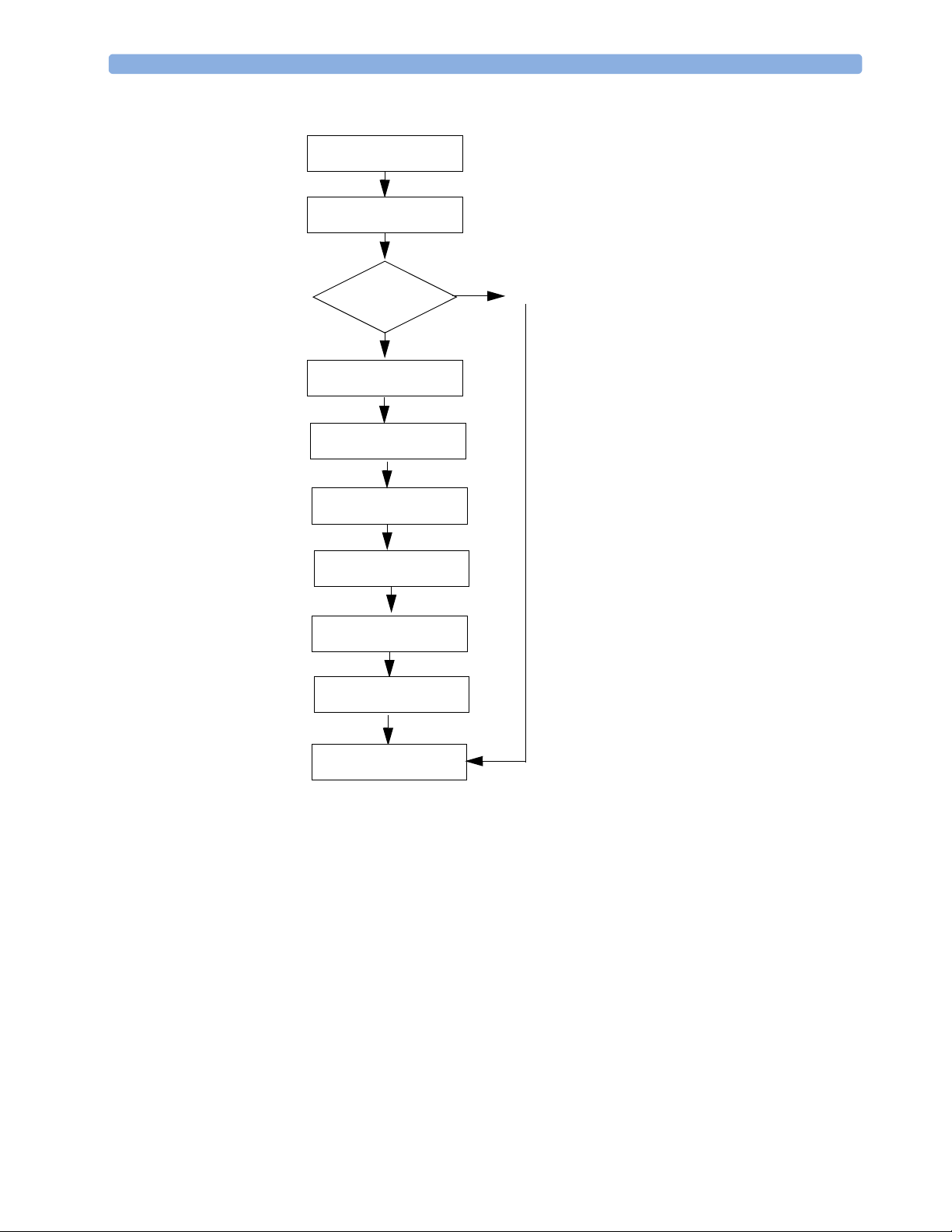
3 Troubleshooting Troubleshooting Flowcharts
Figure 22 RFU Indicator Blinking X No Chirp
Blinking X no chirp
Insert charged battery (20%
capacity)
RFU displays
Hourglass?
No
Turn on device
Run Operational Check
Check Status log
Troubleshoot device, using
tables, if necessary
Repair, if necessary
Yes
Run Performance
Verification tests, if
necessary
Place device back in service
50
Page 61
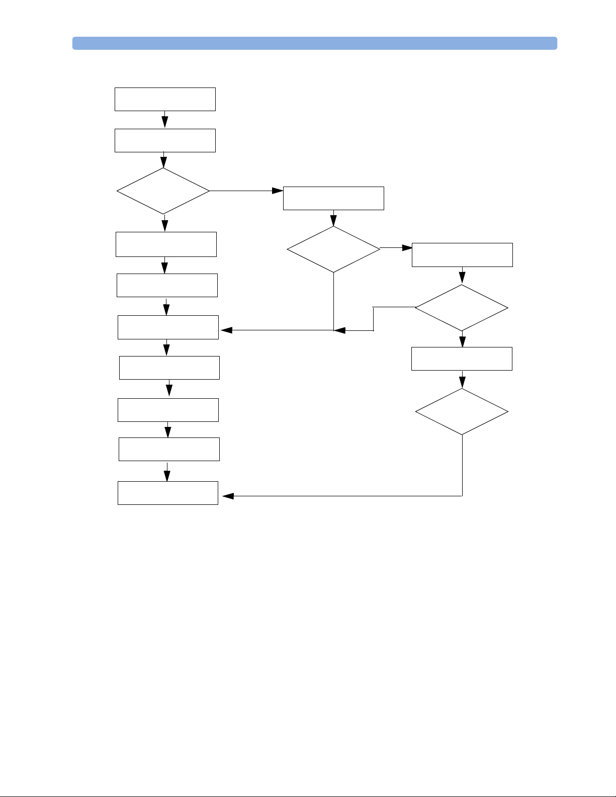
Troubleshooting Flowcharts 3 Troubleshooting
Figure 23 RFU Indicator Solid X With Chirp
Solid X with chirp
Turn on device
ECG message
displayed?
No
Acknowledge failure
message (shock or pacing,
functions)
Run Operational Check
Check Status log
Troubleshoot device, using
tables, if necessary
Repair
Run Performance
Verification tests
Yes
Run Operational Check with
ECG cable
ECG test fails?
No
Yes
Run ECG test without ECG
No
cable
ECG test passes?
Replace ECG cable
Operational Check
passes?
Yes
Yes
Place device back in service
51
Page 62

3 Troubleshooting Troubleshooting Flowcharts
Figure 24 RFU Indicator Solid X No Chirp
Solid X no chirp
Check power source
RFU displays
Hourglass, no
inops?
No
Device turns on?
Yes
Run Operational Check
Check Status log
Troubleshoot device, using
tables, if necessary
Repair, if necessary
Run Performance
Verification tests
No
Yes
Replace Processor PCA
Device turns on?
Yes
No
Call Response Center
52
Place device back in service
Page 63

Troubleshooting Tables 3 Troubleshooting
Troubleshooting Tables
The Troubleshooting tables provide information on messages and common troubleshooting issues.
NOTE Before replacing any components, always run an Operational Check and check the Status log for
errors. Before replacing any parts, check to see if all the cables and flex circuits are properly connected
See “Repair Notes” on page 82.
This section is organized into the following tables:
To p ic Pa g e To p i c Pa ge
Audio Tones 54 Defibrillation Problems 70
Status Log Errors 55 Pacing Problems 70
Startup Errors 62 Printing Problems 74
General Problems 63 Display Problems 75
ECG Monitoring Problems 64 Audio Problems 75
NBP Monitoring Problems 66 Controls Problems 76
SpO
Monitoring Problems 67 Internal Memory Problems 77
2
CO
Monitoring Problems 68 External Data Card Problems 77
2
53
Page 64

3 Troubleshooting Troubleshooting Tables
Audio Tones
The HeartStart MRx emits tones to alert you to its status.
Table 5 Audio Tones
Tone/Indication Definition
Single beep. Message tone. Accompanies a new message on the display. Informational such as
switching to the other battery.
Continuous tone, lower pitch than
charged tone.
Continuous tone. Charged tone. Generated when the selected defibrillation energy is reached and
Periodic chirp. Low battery or RFU failure. Repeated periodically while the condition exists.
Continuous tone, alternating pitch. Device will shut down in one minute.
Tone repeated once a second.
Red alarm indicator message for
applicable HR/arrhythmia, apnea,
and extreme desat alarms.
High pitched tone repeated five
times followed by a pause.
Red alarm indicator message for
applicable HR/arrhythmia, apnea,
and extreme desat alarms.
Tone repeated every two seconds,
lower pitch than red alarm tone.
Yellow alarm indicator message for
applicable HR/arrhythmia, SpO
NBP, and EtCO
alarms.
2
Lower pitched tone is repeated three
times, followed by a pause.
Yellow alarm indicator message for
applicable HR/arrhythmia, SpO
NBP, and EtCO
alarms.
2
Tone repeated every two seconds,
lower pitch then yellow alarm tone.
Cyan indicator message.
Lower pitched tone is repeated
twice, followed by a pause.
Cyan indicator message.
Tone occurring synchronously with
each heart beat.
Charging tone. Generated when the Charge button is pressed and continues until the
device is fully charged.
continues until the Shock button is pressed, the [Disarm] soft key is pressed, or the
device disarmed automatically after the configured time had elapsed since pressing the
Charge button.
Philips’ Red Alarm Tone:
Generated while at least one red alarm is occurring.
80.5 dB
IEC Red Alarm Tone:
Generated while at least one red alarm is occurring.
76.5 dB
Philips’ Yellow Alarm Tone:
Generated while at least one yellow alarm is occurring.
67.4 dB
,
2
IEC Yellow Alarm Tone:
Generated while at least one yellow alarm is occurring
73.4 dB
,
2
Philips’ Inop Tone:
Generated while at least one inop condition is occurring.
IEC Inop Tone:
Generated while at least one inop condition is occurring.
QRS tone.
54
Page 65

Troubleshooting Tables 3 Troubleshooting
Status Log Errors
The Status log includes entries for all errors logged during normal operating mode, Automated tests,
Service and Configuration Mode, and Operational Checks. In some cases, an inop also appears on the
screen, when in normal operating mode. Non-critical conditions, such as low battery, and calibration
due, are not listed in the Status log.
Each entry includes the:
• date and time of the error
• most likely module or PCA that failed
• 8-digit error code for software errors (for factory use)
• optional additional information about the error
• device operating mode at the time of the error
The status log can contain up to 50 entries, with 25 being displayed on a single screen.
NOTE Clear the Status log after a successful Operational Check by pressing the Menu Select button from the
Status log menu and selecting Clear Log.
To view the Status log:
1 Access Service Mode.
See “Accessing Service Mode” on page 10.
2 From the Service Mode Main menu, select Status Log and press the Menu Select button.
55
Page 66

3 Troubleshooting Troubleshooting Tables
Prev
Page
3
Press the [Print Log] soft key if you want to print the report
Figure 25 Status Log Screen
26 Apr 2003 10:52
Prev
Page
.
STATUS LOG
Next
Page
Print
Log
Status Log
Clear Log
Exit
Service
25 Apr 2003 10:50 Selftest - NBP Module (autotest)
24 Apr 2003 15:15 Disconnect Failed - 12LXmit Device
23 Apr 2003 8:15 Internal Fan Failure - Fan Assembly (service)
22 Mar 2003 5:20 Communication - NBP Module (autotest)
21 Mar 2003 11:00 Processor 5V - Power PCA (opcheck)
20 Feb 2003 13:20 ECG Gain Accuracy - Processor PCA (service)
19 Feb 2003 7:45 ECG Bias - Processor PCA (opcheck)
18 Jan 2003 15:15 Main Software 0x00A00151 (runtime)
17 Jan 2003 2:25 No response - 12LXmit Device
16 Jan 2003 2:24 Communication - SpO2 Module (autotest)
15 Dec 2002 18:18 Communication - SpO2 Module (autotest)
14 Dec 2002 18:18 Communication - Printer Assembly (opcheck)
13 Dec 2002 3:30 Communication - Printer Assembly (opcheck)
12 Nov 2002 17:05 Main Software 0x00C00082 (runtime)
11 Oct 2002 11:11 ECG 5V - Processor PCA (autotest)
10 Oct 2002 7:25 Configure Failed - 12LXmit Device
9 Oct 2002 5:23 Main Software 0x00C00082 (runtime)
8 Oct 2002 4:23 Selftest - NBP Module (autotest)
7 Oct 2002 4:23 Communication - SpO2 Module (autotest)
6 Oct 2002 4:23 Selftest - Printer Assembly (autotest)
5 Oct 2002 5:23 Pads Noise - Processor PCA (autotest)
4 Oct 2002 5:15 DSP Communication - Processor PCA (autotest)
3 Oct 2002 3:25 Pads Noise - Processor PCA (autotest)
2 Sep 2002 1:20 Selftest - CO2 Module (opcheck)
1 Sep 2002 1:20 Selftest - CO2 Module (opcheck)
Main
Service
56
Page 67

Troubleshooting Tables 3 Troubleshooting
Table 6 Status Log Errors
Inop Status Log Error Suggested Solution
Fan Failure Internal Fan Failure Replace Fan assembly.
Power Supply Failure Processor 5V Replace Processor PCA.
Therapy 5V Replace Therapy PCA.
Therapy 5V Replace Power PCA.
V Standby Replace AC/DC power module.
Replace Power PCA.
12V Supply Replace Power PCA.
3V Supply Replace Power PCA.
3V Standby Replace Processor PCA.
Ground Voltage Replace Processor PCA.
Shock Equip Malfunction Charge/Shock Failure Replace Therapy PCA.
Pacing Failure Replace Therapy PCA.
Pacer Equip Malfunction Pacing Failure Replace Therapy PCA.
ECG Equip Malfunction ECG Gain Replace Processor PCA.
ECG Noise Replace Processor PCA.
ECG 5V Replace Processor PCA.
ECG Front End Failure Replace Processor PCA.
ECG Bias Replace Processor PCA.
ECG Cable Failure ECG Bias Replace ECG cable.
Pads Cable Failure Pads Bias Replace Pads cable.
Paddles Cable Failure Pads Bias Replace Pads cable.
Pads ECG Equip Failure Pads Gain Replace Power PCA.
Pads Noise Replace Power PCA.
Pads 5V Replace Power PCA.
Pads PCI Replace Pads cable/Power PCA.
Paddles in Pockets Replace Pads cable/Power PCA.
Pads Impedance Replace Pads cable/Power PCA.
Pads Bias Replace Power PCA.
NBP Equip Malfunction Self test Replace NBP module.
Communication Replace NBP module.
SpO
Equip Malfunction Self test Replace SpO2 module.
2
Communication Replace SpO
module.
2
57
Page 68

3 Troubleshooting Troubleshooting Tables
Table 6 Status Log Errors (Continued)
Inop Status Log Error Suggested Solution
CO2 Equip Malfunction Self test Replace CO2 module.
Communication Replace CO
module.
2
Printer Malfunction Selftest Replace printer.
Communication Replace printer.
Incompatible Printer Unsupported language - Printer
Assembly
The 50mm printer is in the device and the software is
looking for the 75 mm printer. Install the 75 mm
printer in the device.
None. SW Watchdog Fail If recurring, reload software and contact Response
Center.
The following table lists additional actions to try if the suggested solution in Table 6 does not fix the
problem.
Table 7 Additional Solutions
Inop Status Log Error Suggested Solution
NBP Equip Malfunction Communication • Replace NBP module cable.
• Replace case interconnect ribbon cable.
• Replace Processor PCA.
SpO
Equip Malfunction Communication • Replace measurement module panel.
2
• Replace Processor PCA.
Selftest • Replace Processor PCA.
CO
Equip Malfunction Communication • Replace CO2 module ribbon cable.
2
• Replace case interconnect ribbon cable.
• Replace Processor PCA.
Printer Malfunction Communication • Replace printer data cable.
• Replace Processor PCA.
The following table lists the messages and corresponding 12-lead transmission errors that can appear in
the status log. For additional information on 12-lead transmission implementation, see the 12-Lead
Transmission Implementation Guide (M3536-90900).
58
Page 69

Troubleshooting Tables 3 Troubleshooting
Table 8 12-Lead Transmission Status Log Errors
Error Message Status Log Error Possible Causes Suggested Solutions
Transmission
Settings Have Not
Been Configured
No transmission
devices detected
Missing settings 12LXmit Config
No response 12LXmit Device
The Hub information
settings are not correct.
•The cell phone is not
connected properly.
•The cell phone’s
RS232 port is not
configured correctly.
•The cell phone’s
RS232 port hardware
is incompatible.
• The serial cable is
defective or
incompatible.
Modify the Hub Configuration settings on the
MRx as needed.
• Check that the phone is connected to the serial
cable and that the serial cable is connected to
the RS232 port on the MRx. For some phones,
it may be necessary to disconnect the cable and
reconnect it before each transmission.
• Work with your cell phone provider to enable
the RS232 port on your cell phone.
• Work with your cell phone provider to choose a
phone that is compatible.
•
Work with your cell phone provider to
obtain a serial cable that connects to your
phone with a 9-pin D serial cable
connection
.
Transmission Failed.
Error configuring
transmission device
No Dial tone
Configure Failed 12LXmit Device
No Dial tone 12LXmit Dialing
•The cell phone is not
set up properly.
The Configuration String
under the Serial Phone
Profile settings is not
correct.
•The cell phone is not
connected properly.
• Cell phone service is
unavailable.
• Work with your cell phone provider to ensure
that the cell phone is set up as a modem using
the RS232 port.
Work with your cell phone provider to ensure that
the Configuration String is correct.
• Check that the phone is connected to the serial
cable and that the serial cable is connected to
the RS232 port on the MRx.
• Check that the cellular signal strength is
sufficient.
59
Page 70

3 Troubleshooting Troubleshooting Tables
Table 8 12-Lead Transmission Status Log Errors (Continued)
Error Message Status Log Error Possible Causes Suggested Solutions
Transmission Failed.
Connection Failed
Invalid Password
Transmission Failed
• Connect Failed 12LXmit Dialing
• Disconnect Failed
- 12LXmit
Dialing
• User/pw failure 12LXmit Network
• User/pw failure 12LXmit Server
• PPP Attach
Timeout 12LXmit Network
•Request Timeout
- 12LXmit Server
• Partial
transmission - 12L
Tr a n s m i t
• Invalid request 12L Transmit
• The Dial String under
the Serial Phone
Profile settings is
incorrect.
• Data transfer service is
unavailable on the
phone.
•Wrong number.
• The PPP User Name
or PPP Password
under the Serial
Profile Phone settings
is incorrect.
• The server User Name
or Password is
incorrect.
• The network is down.
•The server connection
has timed out.
• The phone is
disconnected.
• TCP/IP Failure
• Work with your cell phone provider to ensure
that the Dial string is correct.
• Work with your cell phone provider to ensure
that your cell phone plan has data transfer
capability.
• Check the number and re-send.
• Modify the Serial Phone Profile setting as
needed.
• Modify the Hub settings as needed.
• Check with your ISP to see if your service is
down.
• Re-send the 12-lead report.
• Check that the phone is connected to the serial
cable and that the serial cable is connected to
the RS232 port on the MRx.
• Re-send the 12-lead report. If still unsuccessful,
check the MRx configuration settings.
Transmission Failed.
Connection
Interrupted
.
Transmission Failed.
Cannot reach server
Transmission Failed.
Server unknown
60
• HTTP client error
- 12L Transmit
Modem Connection
Lost - 12LXmit
Network
Unreachable 12LXmit Server
DNS query failure 12LXmit Server
• The web server has
rejected the data.
The network is down. • Check that the cellular signal strength is
No server or the
connection has been lost.
• The DNS has timed
out or there has been a
failure in the DNS.
• Check the MRx and the12-Lead Transfer
Station to ensure that the correct product
versions are installed.
sufficient.
• Re-send the 12-lead report.
• Check that the phone is connected to the serial
cable and that the serial cable is connected to
the RS232 port on the MRx.
• Re-send the 12-lead report.
Work with your ISP to ensure the Serial Phone
Profile and Hub settings are correct.
Page 71

Troubleshooting Tables 3 Troubleshooting
Table 8 12-Lead Transmission Status Log Errors (Continued)
Error Message Status Log Error Possible Causes Suggested Solutions
Transmission Failed.
Settings Configured
Incorrectly
•Bad URL Format
- 12LXmit Server
• Bad proxy settings
- 12LXmit Server
•Bad user/pw
settings 12LXmit Server
• There is a problem
with the Server URL,
Proxy user name,
Proxy password
Work with your ISP to ensure the Serial Phone
Profile and Hub settings are correct.
61
Page 72

3 Troubleshooting Troubleshooting Tables
Startup Errors
This section discusses errors that can occur at startup.
Table 9 Startup Errors
Message Suggested Solution
Critical Failure Detected. Service unit. • Check the status log.
•Reload software
Device serial number has not been entered. Service
unit.
None. Hourglass appears on RFU indicator but
device appears frozen when you turn the Therapy
Knob to Monitor.
All settings have been set to factory default values. • Reconfigure the device to the user’s settings. See the
• Internal Memory Failure message with a beep
• Internal Memory Failure inop (appears every time
the device is turned on)
• Enter the device’s serial number. See “Entering the Serial
Number and Enabling Options” on page 128 for more
information.
• Remove all power sources (AC, DC, and/or battery).
• Turn Therapy Knob to Monitor.
• Insert a battery or apply AC/DC power module.
Instructions for Use for details.
• None. Internal memory card is automatically
reformatted. All data on the card has been erased.
• Run an Operational Check and check the status log. If an
Internal Memory error is listed, replace the internal
memory card.
62
Page 73

Troubleshooting Tables 3 Troubleshooting
General Problems
The following table discusses general problems that can occur.
Table 10 General Monitoring Problems
Symptom Pos sible Causes Suggested Solution
Replace Clock Battery
message
One or more controls don’t
respond (e.g., select lead or
soft keys).
The clock (lithium) battery
(on the Processor PCA)
needs to be replaced.
Bad connection between
keys and detection circuits.
Failure in keypress detection/
processing.
Failure in keys. • Replace Display assembly.
• Replace clock battery on Processor PCA.
• Run Controls test in Service Mode to
confirm.
• Check flex circuit connections between
Display assembly and Processor PCA.
• Replace
Processor PCA.
63
Page 74

3 Troubleshooting Troubleshooting Tables
ECG Monitoring Problems
TIP When troubleshooting ECG problems, always check the cable first by running an Operational Check.
When troubleshooting problems with paddles, try replacing the paddles first.
Table 11 ECG Monitoring Problems - Leads
Symptom Pos sible Causes Suggested Solution
Flat line - no waveform, no
Leads Off message.
Poor ECG signal quality (noisy trace, wandering
baseline, etc.) from signal
acquired from monitoring
electrodes.
Leads Off message even
though ECG cable and leads
have been replaced and are
properly connected.
Short in patient cable or
leads.
• Radio frequency
interference (RFI) is
causing artifact.
• Problem with internal
cables.
•Problem with
measurement module
panel.
Open circuit in internal
Leads ECG wiring or front
end, due to:
•Problem with
measurement module
panel.
Run the Operational Check with the ECG
cable. If the test fails, run it without the
ECG cable. If the test passes, replace the
cable. If the test fails:
• Replace measurement module panel.
• Replace Processor PCA.
• Relocate or turn off equipment that may
be causing RFI.
• Be sure all internal cables are connected
properly. Check the cables from the
measurement module panel to the
Processor PCA.
• Run the Operational Check with the
ECG cable. If the test fails, run it
without the ECG cable. If the test passes,
replace the cable. If the test fails, replace
Processor PCA.
• Replace measurement module panel.
64
Page 75

Troubleshooting Tables 3 Troubleshooting
Table 12 ECG Monitoring Problems - Pads/Paddles
Symptom Possible Causes Suggested Solution
Flat line - no waveform, no
Pads Off message.
Poor ECG signal quality (noisy trace, wandering
baseline, etc.) from signal
acquired from paddles/pads.
Pads Off message even
though pads cable has been
replaced and is properly
connected.
Short in patient cable. Run the Operational Check with the Pads
cable. If the test fails, run it without the
Pads cable. If the test passes, replace the
cable. If the test fails:
• Replace Therapy port.
•Replace Power PCA.
• Radio frequency
interference (RFI) is
causing artifact.
• Problem with internal
cables.
• Problem with Therapy
port.
Open circuit in internal
Therapy port wiring or front
end, due to:
• Cable from Therapy port
to Therapy PCA has bad
connection.
• Defective Therapy port or
cable to Power PCA.
• Problem with internal
cable.
• Defective Power PCA. • Replace Power PCA.
• Relocate or turn off equipment that may
be causing RFI.
• Be sure all internal cables are connected
properly. Check the cables from the
Therapy port to the Therapy PCA and
from the Therapy PCA to the Power
PCA.
• Run the Operational Check with the
Pads cable. If the test fails, run it without
the Pads cable. If the test passes, replace
the cable. If the test fails, replace Power
PCA.
• Replace Therapy port.
• Reconnect cable properly.
• Replace Therapy port.
• Replace Therapy-Power-High Voltage
cable.
65
Page 76

3 Troubleshooting Troubleshooting Tables
NBP Monitoring Problems
Table 13 NBP Monitoring Problems
Symptom Pos sible Causes Suggested Solution
NBP Equip Malfunction NBP hardware malfunction. • Replace NBP module.
NBP Calibration Overdue The NBP module should be
calibrated once a year or
every 10,000 cycles.
NBP Measurement Failed A measurement value could
not be obtained.
NBP Service Required The NBP module has
reached its end of life,
defined as 50,000 cycles.
Measurement cycle doesn’t
start.
Pump operates, cuff inflates
normally, but cuff will not
deflate.
Reading inaccurate • NBP module needs
• Problem with internal
tubing connections.
•Failure of front panel
button.
• NBP module failure. • Replace NBP module.
• Processor PCA failure. • Replace Processor PCA.
NBP module failure. • Replace NBP module.
calibration.
• NBP module failure. • Replace NBP module.
• Calibrate the NBP module. See
“Checking the NBP Module” on page 19.
• Check accuracy as described in “Checking
the NBP Module” on page 19. Calibrate if
needed.
• Replace NBP module.
• Check internal tubing. Reconnect/replace
as needed.
• Run Controls test in Service Mode to
confirm. Replace Display assembly if
needed.
• Check accuracy as described in “Checking
the NBP Module” on page 19. Calibrate if
needed.
66
Page 77

Troubleshooting Tables 3 Troubleshooting
SpO2 Monitoring Problems
Table 14 SpO2 Monitoring Problems
Symptom Pos sible Causes Suggested Solution
SpO2 Sensor Malfunction
Numeric is replaced with
The SpO2 sensor or cable is
faulty.
a -?-.
SpO
Equip Malfunction The SpO2 hardware is
2
faulty.
No response - no value on
screen, no pleth bar.
Reads obviously wrong
value.
•Bad sensor.
• Bad internal connection.
•SpO
PCA failure. • Replace SpO2 PCA.
2
•Bad sensor.
•SpO
PCA failure.
2
Noisy/intermittent signal. • Bad sensor.
• Processor PCA failure.
• Try another sensor and cable.
• If this does not clear the message, replace
SpO
PCA.
2
• Replace measurement module panel.
• Unplug and replug the PCA.
• If this does not clear the message, replace
SpO
PCA.
2
• Try another sensor and cable.
• Try flexing the SpO
flex circuit to see if
2
there is an intermittent failure that may
self-correct while other tests are being
conducted.
• Carefully re-seat the flex circuit between
SpO
port and SpO
2
SpO
PCA is properly seated on Processor
2
PCA. Check that
2
PCA.
• Try another sensor and cable.
• Replace SpO2 PCA.
• Try another sensor and cable.
• Replace Processor PCA.
67
Page 78

3 Troubleshooting Troubleshooting Tables
CO2 Monitoring Problems
When troubleshooting CO2 problems, it is recommended that you try replacing the CO2 module first.
If the problem persists, then replace all of the CO
internal tubing, intake receptacle wires and tubing.
2
Tab l e 15 C O
Monitoring Problems
2
Symptom Possible Causes Suggested Solution
CO2 Equip Malfunction CO2 hardware malfunction. • Make sure that you have the correct
module in the device. See “Other
Electrical Assemblies” on page 216 for
CO
Occlusion A sample cannot be taken
2
because the FilterLine is
blocked.
information on ordering the CO
• Replace the CO
module.
2
• Check that the FilterLine is not kinked
and is free of any blockages.
• Disconnect and reconnect the FilterLine
module.
2
to reset the module.
• If necessary, replace the FilterLine.
• If the message still appears, replace the
CO
internal tubing and intake receptacle
2
CO
Calibration
2
Overdue
The CO2 module should be
calibrated once a year or after
wires and tubing. Replace CO
• Calibrate the CO2 module. See “Checking
the CO
Module” on page 23.
2
module.
2
4,000 operating hours.
Service Required The CO2 module has
CO
2
reached its end of life,
defined as 15,000 operating
•Replace CO
module, all CO2 internal
2
tubing and intake receptacle wires and
tubing.
hours.
CO
Overrange • The CO2 value is higher
2
than the measurement
range.
• Problem with internal
tubing connections.
• Check accuracy as described in “Checking
the CO
Module” on page 23. Calibrate if
2
needed.
• Check internal tubing.
• Reconnect/replace internal tubing and
intake receptacle wires and tubing, as
needed.
Failure to display CO
measurement.
•CO
•CO2 module failure. • Replace the FilterLine.
2
module failure. • Replace CO2module.
2
• Re-seat both ends of the wire between the
intake receptacle and the CO
module.
2
• Replace case interconnect ribbon cable.
68
• Internal tubing broken or
damaged.
•Replace CO
• Replace the CO
intake receptacle wires and tubing.
module.
2
internal tubing and
2
• Processor PCA failure. • Replace Processor PCA.
• Therapy PCA failure • Replace Therapy PCA.
Page 79

Troubleshooting Tables 3 Troubleshooting
Tab l e 15 C O2 Monitoring Problems (Continued)
Symptom Possible Causes Suggested Solution
Reading inaccurate. • FilterLine is blocked or
damaged
•CO
module needs
2
calibration.
•CO
module failure. • Replace CO2module.
2
• Problem with internal
tubing connections.
CO
Check Exhaust When CO2 is turned on, the
2
exhaust tube or outlet port is
blocked to the extent that a
measurement sample cannot
be taken.
Note: If the exhaust tube
becomes blocked during
monitoring, the CO
2
waveform will be a flat line,
and if alarms are on, an
apnea alarm will be
annunciated.
The CO
module does
2
not start when the
FilterLine is connected
to the MRx. There is no
CO
waveform on the
2
• FilterLine is damaged.
• Intake receptacle failure
•CO
module failure or
2
sensor failure
display.
Replacement
recommended
CO
module has reached
2
end of life
• Replace FilterLine.
• Check accuracy as described in “Checking
the CO
Module” on page 23. Calibrate if
2
needed.
• Check internal tubing and intake
receptacle wires and tubing.
Reconnect/replace as needed.
• Replace FilterLine.
• Make sure the exhaust tubing is not
kinked and is free of blockages.
• If necessary, replace the internal tubing
and intake receptacle wires and tubing.
Replace CO
module.
2
• Replace FilterLine.
• Run an Operational Check. If the CO
test fails, replace the CO
CO
test passes, examine the sensor for
2
module. If the
2
2
dirt or foreign objects, clean if necessary. If
problem persists, replace the CO
internal
2
tubing, intake receptacle wires and tubing.
Replace CO2 module and CO2 internal
tubing, intake receptacle wires and tubing.
69
Page 80

3 Troubleshooting Troubleshooting Tables
Defibrillation Problems
Table 16 Defibrillation Problems
Symptom Pos sible Cause Suggested Solution
Charging Problems
Won’t c harg e in Manua l
Defib Mode using Charge
button on paddles.
• Paddles not connected
properly.
• Paddles defective. • Confirm paddles problem by connecting
• Problem with internal
connections.
• Therapy port defective. • Replace Therapy port.
• Therapy PCA defective. • Replace Therapy PCA.
• Failure on Processor PCA. • Replace Processor PCA.
• Check/restore connection.
Pads and attempting to charge device
using Charge button on the MRx.
• Replace paddles if needed.
• Check/restore connections between
Therapy port and Therapy PCA, and
between Therapy PCA and Processor
PCA.
70
Page 81

Troubleshooting Tables 3 Troubleshooting
Table 16 Defibrillation Problems (Continued)
Symptom Pos sible Cause Suggested Solution
Won’t c harg e in Manua l
Defib Mode using Charge
button on MRx.
Won’t c harg e in A ED Mode,
but charges in Manual Defib
Mode.
Doesn’t charge to energy
setting on Therapy switch.
• Therapy cable. • Connect paddles or pads. Check to see if
an ECG is displayed. If the device
recognizes the Therapy cable but still
doesn’t charge, there may be a break in the
Therapy cable.
• Replace Therapy cable.
•Failure of front panel
button.
• Therapy PCA defective. • Replace Therapy PCA.
• Failure on Processor PCA. • Replace Processor PCA.
• Failure in pads ECG front
end.
• Failure on Processor PCA. • Replace Processor PCA.
• Therapy Knob has been
replaced and installed
incorrectly.
• Therapy switch failure. • Replace Therapy switch.
• Therapy PCA defective. • Replace Therapy PCA.
• Failure on Processor PCA. • Replace Processor PCA.
• Run Controls test in Service Mode to
confirm. Replace Display assembly, if
needed.
•Replace Power PCA.
• Confirm by rotating Therapy Knob back
and forth to check travel and alignment.
• Run Controls test in Service Mode to test
Therapy Knob. Reinstall Therapy Knob, if
necessary.
71
Page 82

3 Troubleshooting Troubleshooting Tables
Table 16 Defibrillation Problems (Continued)
Symptom Pos sible Cause Suggested Solution
Charges too slowly. • The device is being
operated with AC/DC
power (no battery) or the
battery power is low.
• Battery not fully charged,
or defective.
• Therapy PCA defective. • Replace Therapy PCA.
Discharging Problems
Won’t Shock in Manual
Defib mode using Shock
buttons on paddles.
Won’t Shock in Manual
Defib mode using Shock
button on MRx.
Won’t Shock in AED mode
when Shock button pressed.
Doesn’t deliver correct
energy into defibrillator
analyzer or delivers no
energy at all. “Shock Equip
Malfunction” error is
displayed.
• Faulty paddles. • Confirm paddles problem by connecting
• Problem with internal
connections.
• Therapy port defective. • Replace Therapy port.
• Therapy PCA defective. • Replace Therapy PCA.
• Failure on Processor PCA. • Replace Processor PCA.
•Failure of front panel
button.
• Therapy PCA defective. • Replace Therapy PCA.
• Failure on Processor PCA. • Replace Processor PCA.
•Failure of front panel
button.
• Therapy PCA defective. • Replace Therapy PCA.
• Failure on Processor PCA. • Replace Processor PCA.
• Therapy PCA defective. • Replace Therapy PCA.
• Failure on Processor PCA. • Replace Processor PCA.
• Install a fully charged battery.
• Install a fully charged battery.
Pads and attempting to discharge device
using Shock button on the MRx. Replace
paddles if needed.
• Check/restore connections between
Therapy port and Therapy PCA, and
between Therapy PCA and Processor
PCA.
• Run Controls test in Service Mode to see if
button is operating. Replace Display
assembly, if needed.
• Run Controls test in Service Mode to
confirm.
72
Page 83

Troubleshooting Tables 3 Troubleshooting
Table 16 Defibrillation Problems (Continued)
Symptom Pos sible Cause Suggested Solution
Discharges only partially some energy remains after
discharge.
Charges OK, but disarms
when press Shock or paddle
buttons.
Charges OK, but disarms
spontaneously.
Doesn’t measure its own
delivered energy correctly.
• Therapy PCA defective. • Replace Therapy PCA.
• Failure on Processor PCA. • Replace Processor PCA.
Patient impedance sensed as
too high or too low during
energy delivery due to:
• Pads/paddles losing
contact with patient.
• Pads/paddles failure.
• Pads cable failure.
• Therapy PCA defective. • Replace Therapy PCA.
• Failure on Processor PCA. • Replace Processor PCA.
Device sensed Pads Off or
Cable Off due to:
• Pads/paddles losing
contact with patient.
• Pads/paddles failure.
• Pads cable failure.
Therapy PCA failure.
Processor PCA failure.
Therapy PCA failure. • Replace Therapy PCA.
• Replace paddles, or pads and pads cable. as
needed.
Replace paddles, or pads and pads cable.
• Replace Therapy PCA.
• Replace Processor PCA.
Pacing Problems
Symptom Pos sible Causes Suggested Solution
Doesn’t deliver correct
current into pacer tester or
delivers no current at all.
Doesn’t measure its own
delivered current correctly.
Doesn’t pace at correct rate. Processor PCA failure. Replace Processor PCA.
Pacer Equip Malfunction Pacer hardware failure. Replace Therapy PCA.
Table 17 Pacing Problems
• Failure on Therapy PCA. • Replace Therapy PCA.
• Processor PCA failure. • Replace Processor PCA.
Failure on Therapy PCA. Replace Therapy PCA.
73
Page 84

3 Troubleshooting Troubleshooting Tables
Printing Problems
Table 18 Printing Prolems
Symptom Pos sible Causes Suggested Solution
Printer Malfunction The printer is faulty or there
is a problem communicating
with the printer.
Paper won’t move. • Paper improperly loaded
or jammed, or paper is
wet.
• Printer failure. • Replace printer.
Paper moves but printing is
faint or absent.
Paper moves but print
quality poor or some dots
missing.
Loud buzzing or grinding
noise.
Waveforms or text distorted
even though they look OK
on display.
Black line running along
paper.
White line running along
paper.
Fails Printer Test in Service
Mode (other than symptoms
above).
Incompatible Printer • The 50mm printer is in
• Door improperly latched. • Check door latch.
• Dirty printhead. • Clean printhead according to procedures
• Operating temperature is
beyond specified range.
• Printer failure. • Replace printer.
• Dirty printhead. • Clean printhead according to procedures
• Printer failure. • Replace printer.
Door improperly latched. Check door latch.
Printer failure. Replace printer.
Dots (printhead elements)
stuck on due to:
Printer failure. Replace printer.
Dirt on printhead. • Clean printhead.
Dots (printhead elements)
stuck off due to:
• Printer failure. • Replace printer.
• Printer failure. • Replace printer.
• Processor PCA failure. • Replace Processor PCA.
the device and the
software is looking for the
75 mm printer.
If the error repeats, replace the printer
assembly.
• Reload paper or clear jam. If paper is wet,
replace with fresh dry roll.
in the Instructions for Use.
• Wait until temperature is back in
operating range to continue printing.
in the Instructions for Use.
• Ensure that the 75 mm printer is installed
in the device
74
Page 85

Troubleshooting Tables 3 Troubleshooting
Display Problems
Table 19 Display Problems
Symptom Pos sible Causes Suggested Solution
Display completely dim. No
response - all light or all
dark.
Left or right half of display is
dim or display is not
uniformly bright.
Fails Display Test in
Operational Check. (Display
problem other then
symptoms above).
Audio Problems
Symptom Pos sible Causes Suggested Solution
• Failure of backlight.
•Display failure.
• No power supply or
power supply failure
• Processor PCA failure.
• Backlight cable
disconnected from
inverter PCA.
• Backlight bulb failure.
• Display failure. • Replace Display assembly.
• Processor PCA failure. • Replace Processor PCA.
Table 20 Audio Problems
• Check cable between Processor PCA and
inverter.
• Check display and backlight connections.
• Replace Display assembly.
• Replace Power PCA (only if display is all
dark).
• Replace Processor PCA.
• Reseat the connector
• Replace Display assembly.
No audio at all. • Speaker failure. • Check speaker connections.
• Replace speaker/microphone assembly.
• Processor PCA failure. • Replace Processor PCA.
Audio is distorted. • Damage to speaker cover. • Replace speaker label.
• Speaker damage or
failure.
• Processor PCA failure. • Replace Processor PCA.
• Replace speaker/microphone assembly.
75
Page 86

3 Troubleshooting Troubleshooting Tables
Table 20 Audio Problems (Continued)
Symptom Pos sible Causes Suggested Solution
Buzzing noise when audio
active.
Tones present but no voice
prompt (in AED Mode).
Voice prompt present but no
tones.
Controls Problems
Symptom Pos sible Causes Suggested Solution
One or more of the buttons
near the Therapy Knob
doesn’t respond correctly
(Print, Sync, Charge, or
Shock).
One or more of the buttons
around the display doesn’t
respond correctly (softkeys,
Event Summary, Mark
Event, Lead Select, Alarm
Pause, Navigation, Menu
Select).
The Therapy switch doesn’t
respond correctly.
• Damage to speaker label. • Replace speaker label.
• Debris between speaker
and speaker label.
• Speaker hardware loose. • Tighten hardware as needed.
• Speaker failure. • Replace speaker/microphone assembly.
• Processor PCA failure. • Replace Processor PCA.
• Software error or failed
localization upgrade.
• Processor PCA failure.
Processor PCA failure. • Replace Processor PCA.
Table 21 Controls Problems
Processor PCA failure. • Run Controls test in Service Mode to
•Failure in Display
assembly.
• Processor PCA failure. • Replace Processor PCA
• Therapy switch defective. • Replace Therapy switch.
• Processor PCA failure. • Replace Processor PCA.
• Remove speaker label, clean out debris,
install new speaker label. If debris is
behind plastic housing, remove speaker,
clean, and replace speaker.
• Reload the language.
• Replace Processor PCA.
confirm.
• Check button pieces for mechanical
operation.
• Replace Processor PCA.
• Run Controls test in Service Mode to
confirm.
• Check connections to Display assembly.
• Replace Display assembly.
76
Page 87
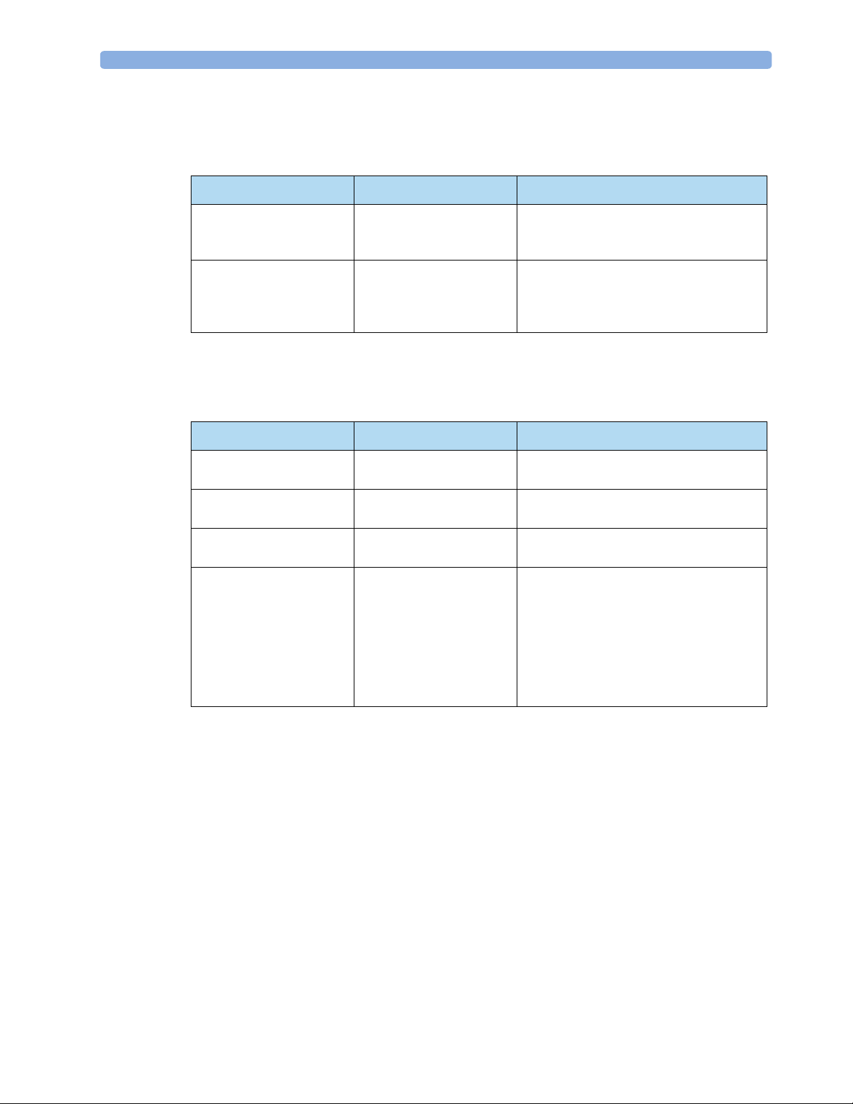
Troubleshooting Tables 3 Troubleshooting
Internal Memory Problems
Table 22 Internal Memory Problems
Symptom Pos sible Causes Suggested Solution
Internal Memory Failure
message with a beep
Internal Memory Failure
inop (appears every time the
device is turned on)
Patient data cannot be stored
in internal memory because
the card is corrupt.
Patient data cannot be stored
in internal memory because
the internal memory card is
not recognized.
External Data Card Problems
Table 23 External Data Card Problems
Symptom Pos sible Causes Suggested Solution
Incompatible data card
message
Data Card Full message The data card has reached
Doesn’t copy data to data
card.
No Data Card present
message.
Data card is not compatible
with the HeartStart MRx.
capacity.
Data card full or corrupted. Replace data card.
• Sufficient time not
allowed for data card
recognition
• Data card failure. • Replace data card.
• Data card not seated
properly due to bent pins.
• Processor PCA failure. • Replace Processor PCA.
None. Internal memory card is automatically
reformatted. All data on the card is erased.
Run an Operational Check and check the
status log. If an Internal Memory error is
listed, replace the internal memory card.
Use only Philips M3545A data cards.
Insert a new data card or erase data from the
card.
• Insert data card. Once inserted, wait 5
seconds before trying to access the data
card.
• Replace Processor PCA.
77
Page 88

Page 89

This chapter describes how to repair the HeartStart MRx monitor/defibrillator. Details are provided on
disassembling the device, removing and replacing subassemblies, and reassembling the device.
These instructions are intended for use only by service providers who are specifically trained to service
the HeartStart MRx.
Overview
This chapter is organized into the following sections:
To p ic Pa ge To pi c Pa ge
4
4Repair
Who Should Perform Repairs
Repair Philosophy
Repair Notes 82 Internal Assemblies - Rear Case 144
Repair Tools and Equipment 85 Closing the case 176
Key Components 85
External Assemblies 86
80
80
Opening the case 102
Internal Assemblies - Front Case 107
79
Page 90

4Repair Who Should Perform Repairs
Who Should Perform Repairs
Only qualified technical personnel who have been trained in the safe and proper servicing of the
HeartStart MRx should open the monitor/defibrillator case, remove and replace components, or make
adjustments. If your medical facility does not have qualified technical personnel, contact the Response
Center or your local Philips representative.
WARNING HeartStart MRx service should only be performed by qualified service personnel, in accordance with
the HeartStart MRx Service Manual.
Repair Philosophy
The repair philosophy of the HeartStart MRx is subassembly replacement.
Examples of subassemblies are the printer, the Processor PCA, and selected connectors and other items.
Repairs that involve replacing individual components on a PCA are not supported.
CAUTION Individual component replacement should not be attempted. Component level repair is inadvisable
due to the extensive use of surface mount technology and the high parts-density on the circuit boards.
Unauthorized component replacement can impair performance of the HeartStart MRx.
80
Page 91

Repair Philosophy 4Repair
Calling for Service
For telephone assistance, call the Response Center nearest to you, or visit our website at:
www.medical.philips.com/cms and follow the links for “CMS Response Center.” Our Biomed
On-Line site can be found at: http://bol.medical.philips.com.
Table 24 Response Center Phone Numbers
North America
Canada 800-323-2280
United States of America 800-548-8833
Europe
European International Sales 41 22 354 6464
Austria 01 25125 333
Belgium 02 778 3531
Finland 010 855 2455
France 0803 35 34 33
Germany 0180 5 47 50 00
Italy 800 825087
Netherlands 040 278 7630
Sweden 08 5064 8830
Switzerland 0800 80 10 23
United Kingdom 07002 43258472
Asia/Asia Pacific
Australia 1800 251 400
China (Beijing) 800 810 0038
Hong Kong
Macau
India:
New Delhi
Mumbai
Calcutta
Chennai
Bangalore
Hyderabad
Indonesia 021 794 7542
Japan 0120 381 557
Korea 080 372 7777
Malaysia 1800 866 188
New Zealand 0800 251 400
Philippines 02 845 7875
Singapore 1800 PHILIPS
Thailand 02 614 3569
Taiwan 0800 005 616
852 2876 7578
0800 923
011 6295 9734
022 5691 2463/2431
033 485 3718
044 823 2461
080 5091 911
040 5578 7974
02 3445 9010
81
Page 92

4Repair Repair Notes
Repair Notes
The following sections give details of how to successfully work with the internal assemblies of the
HeartStart MRx.
Safety Precautions
WARNING Remove all power sources (AC, battery, DC) before opening the device. Failure to do so may allow the
device to charge without warning and could result in serious injury or death.
CAUTION Take the necessary precautions to guard against shock or injury before you conduct
monitor/defibrillator tests or repairs.
• Only properly trained technicians should service the device.
• The device can contain deadly voltages even if the device is turned off.
• Make sure the device is disarmed. (To disarm the defibrillator, press [
has not been pressed within the time period specified in the Time to Auto Disarm Configuration
setting, the defibrillator disarms automatically. Additionally, when the MRx is fully charged, you can
disarm it any time by turning the Therapy Knob to the “Off” position.)
• Make sure that you disconnect all power before opening the device.
• Make sure you discharge the device before working with it.
• Make sure you work in a static safe environment. Use a static control wrist band, in conjunction
with an antistatic pad which is grounded per the manufacturer’s instructions.
• Special cleaning technologies are used during the manufacturing of the PCAs. Be careful not to
touch the surface areas of the PCAs with bare hands. Additionally, oil from hands can affect product
performance.
Flex Circuit Connections
In order for flex circuit connections to function properly, they must be disconnected and reconnected
as follows:
• Always unlatch the PCA-mounted connector before removing the flex circuit, and hold the latch
open while reinserting the flex circuit into the connector.
• When reconnecting, align the flex circuit carefully in its receptacle. Make sure it is both centered
from side to side in the connector and oriented at 90 degrees to the connector.
Disarm]. If the Shock button
82
• Be sure the flex circuit is fully seated in the connector and the connector is properly latched.
Page 93

Repair Notes 4Repair
Flex Circuit Handling
The flex circuits are delicate and can be damaged by improper handling:
• Do not bend sharply.
• Do not scrape the contact surface against other parts.
• Handle the flex with bent tip needle nose pliers whose jaws are covered with a soft material (such as
plastic tubing or tape).
Internal Connections
Whenever troubleshooting indicates a particular PCA may be at fault, it is always good practice to
check all the connections to that PCA and retest before replacing the PCA.
Cable and Assembly Placement
How the wires and cables are routed and dressed inside the chassis plays an important role in two areas:
in preventing long term wear problems, and in reducing electromagnetic and radio frequency
interference emitted by the monitor/defibrillator.
• When you disassemble any part of the device, pay special attention to how cables and wires are
routed.
• When you reassemble the device, be sure to route and dress all cables and wires as they were
originally.
• Return all components to their original position within the case.
Device Reassembly
If you do not reassemble the device correctly, it may no longer be properly sealed. This could result in
water damage to the device. Be sure to maintain the water-resistant seal by:
• Replacing all gaskets in their proper locations.
• Correctly assembling all parts that mate with gaskets (making sure the gaskets are not wrinkled or
pinched).
•Replacing all screws.
• Making sure that screws are not cross-threaded and that they are firmly tightened.
• Tightening M3 screws to 6-inch pounds and M4 screws to 10-inch pounds.
83
Page 94

4Repair Repair Notes
Disposal
Prior to disposal, remove the batteries. Then dispose of the device in accordance with your country’s
regulations for equipment containing electronic parts.
WARNING Properly dispose of or recycle depleted batteries according to local regulations. Do not puncture,
disassemble, or incinerate batteries. Be careful not to short the battery terminals because this could
result in a fire hazard.
WARNING Disposal of the device with the battery inserted presents a potential shock hazard.
WARNING To avoid contaminating or infecting personnel, the environment, or other equipment, make sure you
disinfect and decontaminate the monitor/defibrillator appropriately prior to disposal.
Disposing of Empty Calibration Gas Cylinders
To dispose of empty calibration gas cylinders:
1 Empty the cylinder completely by pushing the pin of the regulator valve or by pulling out the pin
of the fill wave using a tire valve stem wrench or a pair of needle nose pliers.
2 When the cylinder is empty, either remove the valve stem from the fill (or regulator) hole, or drill a
hole in the cylinder.
3 Write “Empty” on the cylinder and dispose of it appropriately for scrap metal.
WARNING Ensure that the cylinder is completely empty before trying to remove the valve stem or drill the tank.
84
Page 95

Repair Tools and Equipment 4Repair
Repair Tools and Equipment
The following tools are needed to perform the procedures in this chapter.
• Torx T10 and T15 drivers (or Torx driver kit, part number 5181-1933). T15 driver shaft should be
at least 3.5-inches (90 mm) long and less than 0.4-inches (10 mm) in diameter to reach down to
recessed case screws.
• Slip-joint pliers or adjustable open-end wrench.
•Straight-bladed screwdriver.
• Nut driver (5/16”) or small adjustable wrench
• #2 Phillips screwdriver, shaft at least 5” long.
• Straight-tip needle nose pliers or tweezers.
• Bent-tip needle nose pliers whose jaws are covered with a soft material (such as plastic tubing or
tape).
• Fine-nose wire cutters.
• Utility knife.
• Paper clip.
• Clip leads (at least 2, each approx. 10-18”).
• Voltmeter
• Software Support tool (see Table 30 on page 214 for part numbers).
• Defibrillator Discharge Tool (M2475-69573).
Key Components
Replacement assemblies marked with an asterisk ( * ) in the Replacement Parts tables contain one or
more Key Components. Key Components require detailed tracking, by recording the key component
part number and either the key component’s date code or its serial number. This data must be recorded
for both the failed assembly and the replacement assembly.
Philips service personnel must record this information on the Customer Service Order (CSO).
The Key Components that are part of the replacement assemblies are listed in Table 40 on page 229.
85
Page 96

4Repair External Assemblies
External Assemblies
This section describes how to remove and replace assemblies that are external to the case. You do not
need to open the case for any of these procedures.
This section is organized into the following topics:
To p ic P a ge To pi c P ag e
Accessory Pouches 87 Printer Assembly 93
Bedrail Hook Mount 89 Paddle Tray 95
Therapy Knob 90 Paddle Tray 50 ohm Load Resistor 98
Labels 91 Handle and Cap Plate 100
86
Page 97

External Assemblies 4Repair
Accessory Pouches
Preparation
Disconnect all external power and remove all batteries.
Installation
1. Lower the device into the sleeve of the carry case. The rear base of the device fits in the sleeve
socket.
Figure 26 Accessory Pouch Assembly
2. Lift up the paddle tray, if present.
a. If paddles are connected, disconnect them from the Therapy port and remove them from the
paddle tray.
b. Remove the 4 T-15 screws from the tray plates.
c. Gently lift the paddle tray up, leaving all wires connected.
3. Lift up the handle and cap plate, if present.
a. Remove the handle cover by lifting up the notch (with your fingernail or a screwdriver) and
pushing in on either side of the handle cover and lifting up.
b. Remove the 2 T-15 screws.
c. Remove the handle.
d. Gently lift the cap plate up.
87
Page 98

4Repair External Assemblies
4. Fold the two sleeve flaps over the top of the device, positioning them so that the screw holes are
exposed.
5. Replace the paddle tray or cap plate, as appropriate, so that the molded openings fit over the
sleeve flaps.
6. Secure the front and rear cinch straps using the metal rings provided.
7. Attach the side pouches using the snaps located inside the pouch pockets.
Figure 27 Accessory Pouch Assembly
After Repair
Run Performance Verification and Safety testing as described in the "Performance Verification"
chapter.
88
Page 99

External Assemblies 4Repair
Bedrail Hook Mount
Preparation
1. Turn the device off.
2. Position the rear case
Lay the rear case on the work surface with the display facing down and the printer in the lower left
corner.
Removal
1. Loosen and remove the 2 T-15 screws.
2. Remove the bedrail hook mount.
Replacement
1. Secure the bedrail hook mount to the back of the device using the two screws.
After Repair
Visually inspect the device to ensure that you installed the bedrail hook mount correctly. It is not
necessary to run any Performance Verification and Safety testing.
89
Page 100

4Repair External Assemblies
Therapy Knob
Preparation
1. Turn the device off.
2. Disconnect all external power and remove all batteries.
Removal
1. Turn the knob to AED.
2. Pull the knob off its shaft.
Grasp the knob and pull straight out from the front of the device. Use pliers, if necessary.
Figure 28 Therapy Knob Replacement
90
Replacement
1. Push the knob onto the shaft.
a. Align the flat side of the clip inside the knob with the flat surface on the shaft and press the
knob into place. Be sure the knob is pressed fully into place.
b. Check to be sure it rotates freely and that it points to the correct markings on the front panel.
After Repair
Run Performance Verification and Safety testing as described in the "Performance Verification"
chapter.
 Loading...