

Page 1

MONITOR/DEFIBRILLATOR
CONTROLS, CONNECTIONS
AND INDICATORS
Page 2
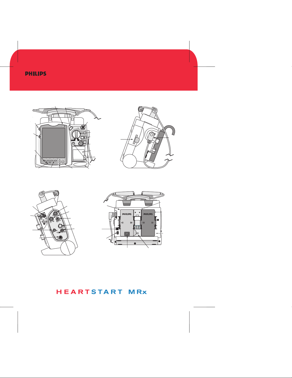
CONTROLS, CONNECTIONS
AND INDICATORS
Mark
Event
Lead
Select
Alarm
Pause
Event
Summary
CO2 Inlet
CO
2
Outlet
Temp
ECG Out
(Sync)
Jack
External Power
Soft
Keys
Navigation
Soft
Keys
1
2
O
C
2
™
E
E
C
C
G
G
SYNC
c
n
y
S
n
n
a
a
M
M
Invasive
Pressure 1
Invasive
Pressure 2
b
b
i
i
100
f
f
e
e
70
D
D
l
l
a
a
50
u
u
30
20
15
1-10
O
P
acer
M
onitor
Menu
Select
NBP
ECG
A
dult
D
ose
120
150
170
200
n
O
n
O
ff
AED
SpO2
Ready For
Use (RFU)
S
elect
Therapy Knob
E
nergy
1
C
harge
2
Charge
S
hock
3
Shock
Speaker
Battery/AC
Compartment B
Printer
Printer
Door Latch
Print
LAN
Connection
RS 232
Serial Port
Data
Card
AC Power Module
Therapy
Connector
Bed Rail Hook
Mount
Battery
Compartment
A
Battery
DC Power Input
453564042471
Edition 1
September 2006
*453564042471*
*1*
MONITOR/DEFIBRILLATOR
Page 3

MONITOR/DEFIBRILLATOR
12-LEAD ECG
Page 4
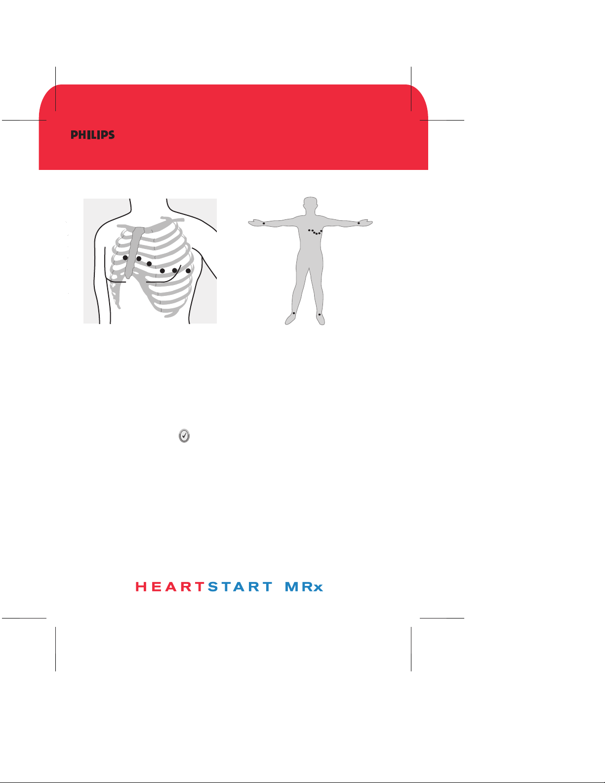
12-LEAD ECG
Electrode Placement for 12-Lead ECG
Acquiring the 12-Lead ECG
1. Turn the Therapy Knob to Monitor.
2. Press the 12-Lead soft key.
3. Check for good signal quality.
4. Press the Start Acquire soft key. If prompted, enter patient age and sex.
5. Keep the patient still during the 10-second acquisition period.
Accessing Stored 12-Lead Reports
1. Press the Menu Select button.
2. Use the Navigation buttons to select Reports.
Reports for the current patient are listed by date and time.
3. Use the Navigation buttons to select a report and press the Menu Select
button.
4. Select Print, Copy, or Delete, and press the Menu Select button.
5. To select another report, repeat steps 1 through 4.
453564042471
Edition 1
September 2006
*453564042471*
*1*
MONITOR/DEFIBRILLATOR
Page 5

MONITOR/DEFIBRILLATOR
ALARMS
Page 6

USING ALARMS
Responding to Alarms
1. Check the patient.
2. Identify the alarm(s) indicated.
3. Silence the alarm(s) by pressing the Menu Select button or one of the
Navigation buttons.
4. Address the alarm condition by selecting one of the following options:
Alarms Off - Turn the monitoring parameter's alarms off, displaying
next to the parameter value.
Acknowledge - Recognize that the alarm condition is present, without
further action. As the default option, Acknowledge always
appears when an alarm occurs.
New Limits - Adjust parameter alarm limits accordingly.
Note: For only Heart Rate/Arrhythmia alarms, your options are either
Acknowledge or Acknowledge and New Limits, depending on the alarm.
Checking/Adjusting Alarm Limits
Alarm limits are preset for your device based on its configuration and the
patient type. When alarms are on, alarm limits are visible next to the
measurement's numeric value.
To adjust an alarm limit setting:
1. Press the Menu Select button.
2. Select Measurements/Alarms and press the Menu Select button.
3. Select the desired measurement from the menu and press the Menu
Select button.
4. Select (measurement) Limits from the menu and press the Menu Select
button.
5. Adjust the limit and press the Menu Select button.
453564042471
Edition 1
September 2006
*453564042471*
*1*
MONITOR/DEFIBRILLATOR
Page 7

MONITOR/DEFIBRILLATOR
MONITORING
CARBON DIOXIDE
Page 8
MONITORING CO
Using the Nasal FilterLine
1. Attach the FilterLine tubing to the CO2 Inlet port.
2. Check that both nostrils are clear.
3. Position the nasal FilterLine on the face by inserting the tips into the nostrils.
4. Pass the FilterLine tubing over the ears, then slide the sleeve up the
tubing toward the neck to a comfortable fit under the chin.
5. If using dual purpose FilterLine tubing, connect the green tubing to
the oxygen source.
6. Check the positioning of the FilterLine regularly to ensure proper function.
Using the FilterLine and Airway Adapter
1. Attach the FilterLine tubing to the CO2 Inlet port.
2. Connect the wide end of the airway adapter to the endotracheal tube.
3. Connect the narrow end of the airway adapter to the ventilator tubing
or manual resuscitator.
Measuring EtCO2 and AwRR
The CO2 waveform is automatically displayed in the configured Wave Sector
when the FilterLine is connected to the CO2 Inlet port. The measurement
values for End-Tidal CO2 (EtCO2) and Airway Respiration Rate (AwRR) are
displayed in Parameter Block 2 as shown below.
2
SpO2SpO
2
100
%
100
90
EtCO2
34
mmHg
50
30
AwRR
18
453564042471
Edition 1
September 2006
*453564042471*
*1*
MONITOR/DEFIBRILLATOR
rpm
30
8
Page 9

MONITOR/DEFIBRILLATOR
MONITOR/DEFIBRILLATOR
MONITORING
MONITORING
ECG
ECG
Page 10

MONITORING ECG
Selecting the Lead for ECG Monitoring
It is important to select a suitable lead for monitoring so that a QRS complex
can be accurately detected.
Guidelines:
- QRS tall and narrow
+
I
–
–
–
III
II
–
–
aVR
+
I
–
aVL
III
aVF
II
- R-wave above or below baseline
(but not bi-phasic)
- T-wave smaller than 1/3 R-wave height
- P-wave smaller than 1/5 R-wave height
+
3-Lead Placement
+
5-Lead Placement
+
+
- For non-transcutaneously paced patients, the pace pulse should be large enough to be
detected with minimal repolarization and not wider than the normal QRS complex.
To select a lead for the primary wave sector:
1. Press the Lead Select button.
2. Cycle through lead choices.
To select a lead for an additional wave sector:
1. Press the Menu Select button.
2. Select Waves and press the Menu Select button.
3. Select the wave sector and press the Menu Select button.
4. Select the desired lead source and press the Menu Select button.
5. If needed, adjust the ECG wave size (gain) and press the Menu Select button.
Note: Arrhythmia analysis occurs at x1 gain (no matter what the display gain is).
Changing Pacing Status
When monitoring patients with non-transcutaneous pacemakers, it is important
to set the paced status correctly. (See MRx Instructions for Use for additional
information.)
To change pacing status:
1. Press the Menu Select button.
2. Select Patient Info and press the Menu Select button.
3. Select Paced and press the Menu Select button.
4. Select Ye s/No and press the Menu Select button.
453564042471
September 2006
*453564042471*
MONITOR/DEFIBRILLATOR
Edition 1
*1*
Page 11

MONITOR/DEFIBRILLATOR
MONITORING
INVASIVE PRESSURES
Page 12

MONITORING
INVASIVE PRESSURES
Changing a Pressure
1. Press the Menu Select button.
2. Using the Navigation buttons, select the Measurement/Alarms menu
and press the Menu Select button.
3. Select Press 1 (or Press 2) and press the Menu Select button.
4. Select Label and press the Menu Select button.
5. Select the appropriate label from the list and press the Menu Select button.
6. Select the size of the scale, the Alarm Source type and high/low Alarm Limits.
Pressure Label Options
ABP - Arterial Blood Pressure ART - Arterial Blood Pressure
Ao - Aortic Pressure CVP - Central Venous Pressure
ICP - Intracranial Pressure* LAP - Left Atrial Pressure
PAP - Pulmonary Artery Pressure RAP - Right Atrial Pressure
P1 - Non-specific Pressure P2 - Non-specific Pressure
Label (Channel 1) Label (Channel 2)
* Cerebral Perfusion Pressure (CPP) is automatically displayed with ICP when
one pressure is already set to ABP, ART or Ao and the other pressure is set
to ICP.
Zeroing
1. Place the transducer at the appropriate level for the measurement site.
2. Close the transducer stopcock to the patient and vent the transducer to
atmospheric pressure. Then pick one of the following methods:
Using Menu Select button Using a soft key in Monitor Mode
3. Press the Menu Select 3. Press the button under [Zero
button. Pressure] on the display.
4. Using the Navigation button, 4. Using the Navigation buttons,
select Measurement/Alarms, select the pressure(s) to zero
press the Menu select button from the Zero menu and press
5. Select the pressure label to the Menu Select button.
zero.
6-Highlight Zero and press the
Menu Select button.
453564042471
Edition 1
September 2006
*453564042471*
*1*
MONITOR/DEFIBRILLATOR
Page 13

MONITOR/DEFIBRILLATOR
MONITORING
NONINVASIVE BLOOD
PRESSURE
Page 14

MONITORING NBP
Preparing
1. Select the appropriately sized cuff.
2. Attach the cuff to the NBP tubing.
3. Insert the NBP tubing into the NBP port.
4. Apply the blood pressure cuff to the patient's arm or leg.
a. Ensure the cuff is completely deflated.
b. Wrap the cuff around the limb.
c. Check that the edge of the cuff falls within the size range markings.
5. Place the limb at the same level as the patient's heart.
Changing the NBP Schedule
1. Press the Menu Select button.
2. Using the Navigation buttons, select the Measurement/Alarms menu
and press the Menu Select button.
3. Select NBP and press the Menu Select button.
4. Select NBP Schedule and press the Menu Select button.
5. Select the desired interval or Manual, and press the Menu Select button.
Interval Options: 1, 2.5, 5, 10, 15, 30, 60 and 120 minutes.
A Manual NBP measurement may be taken at any time by pressing the
Start NBP soft key.
Measuring NBP
To measure NBP, press the Start NBP soft key. Cuff pressure is displayed as
the cuff inflates and deflates. When the measurement completes, the
NBP values are displayed.
HRHR
82 82
NB
120120
6060
PmmHgM
120/80
(100)
453564042471
Edition 1
September 2006
*453564042471*
*1*
MONITOR/DEFIBRILLATOR
anua
SYS 10:
160
90
l
40
Page 15

MONITOR/DEFIBRILLATOR
OPERATIONAL
CHECK
Page 16

OPERATIONAL CHECK
Running the Operational Check
1. Insert a charged battery into the HeartStart MRx.
2. Turn the Therapy Knob to 150J.
3. Press the Menu Select button.
4. Using the Navigation buttons, select Other and press the
Menu Select button.
5. Select Operational Check and press the Menu Select button.
6. Select Run Op Check and press the Menu Select button.
7. Press the Menu Select button to acknowledge the message
Leaving Normal Operating Mode.
8. Carefully read and respond to the prompts.
At the completion of the Operational Check, a report is printed
that lists the test results and prompts you to visually inspect
the device and cables, and to inventory all accessories and supplies.
Note: For device versions greater than or equal to B.05 with Pacing,
run Op Check with a pads cable and test external paddles using the
Weekly Shock Test.
453564042471
Edition 1
September 2006
*453564042471*
*1*
MONITOR/DEFIBRILLATOR
Page 17

MONITOR/DEFIBRILLATOR
NONINVASIVE PACING
(TRANSCUTANEOUS PACING)
Page 18

NONINVASIVE PA C I N G
P
ace
d
R
hythm
(TRANSCUTANEOUS PACING)
Demand Mode Pacing (Requires ECG leads and pads)
1. Turn the Therapy Knob to Pacer.
2. Press the Lead Select button to select the desired lead.
3. Verify white R-wave markers appear above or on the ECG waveform.
4. Press the Pacer Rate soft key, select the desired number of paced pulses
per minute, and press the Menu Select button.
5. If needed, press the Pacer Output soft key, use the Navigation buttons to
adjust the initial pacer output, and press the Menu Select button.
6. Press the Start Pacing soft key.
7. Verify white pacing markers appear in front of every QRS.
8. If cardiac capture is not obtained, press the Pacer Output soft key, increase
the output until capture occurs, decrease the output to the lowest level that still
maintains capture, and press the Menu Select button.
9. Verify the presence of a peripheral pulse.
IIII
Fixed Mode Pacing (Can be done with pads only)
1. Turn the Therapy Knob to Pacer.
2. Set the pacer mode to Fixed.
- Select Pacer Mode from the Main Menu.
- Select Fixed and press the Menu Select button.
3. If using leads, press the Lead Select button to select the desired lead.
4. Press the Pacer Rate soft key, select the desired number of paced pulses
per minute, and press the Menu Select button.
5. If needed, press the Pacer Output soft key, use the Navigation buttons to
adjust the initial pacer output, and press the Menu Select button.
6. Press the Start Pacing soft key.
7. Verify cardiac capture. If it is not obtained, press the Pacer Output soft key,
increase the output until capture occurs, decrease the output to the lowest
level that still maintains capture, and press the Menu Select button.
8. Verify the presence of a peripheral pulse.
NOTE: If monitoring SpO2 when pacing, activate the Pulse alarms
to assess for peripheral perfusion through the SpO2 transducer.
Demand Mode
P
ace
d
R
hythm
Capture
453564042471
September 2006
*453564042471*
Edition 1
*1*
MONITOR/DEFIBRILLATOR
Page 19

MONITOR/DEFIBRILLATOR
TM
Q-CPR
Page 20

Q-CPR
™
Prior to Use
0-8
1. Verify the Pads/CPR cable is connected to the MRx Therapy port.
2. Verify the Compression Sensor is connected to the Pads/CPR cable.
3. Verify a new Compression Sensor Adhesive Pad is applied to the
Compression Sensor.
Preparing for Q-CPR
1. Connect the multifunction electrode pads to the Pads/CPR cable.
2. Apply the multifunction pads to the patient in the anterior/anterior position.
3. Position the Compression Sensor on the patient as shown on the green liner
(i.e., on the lower half of the sternum).
Q-CPR in Manual Defib Mode
- Q-CPR starts automatically when you turn the Therapy Knob to 150J
or perform a chest compression with the Compression Sensor.
- To manually activate Q-CPR, press the Start CPR soft key.
Q-CPR in AED Mode
- Q-CPR starts automatically when you perform a chest compression with the
Compression Sensor during the CPR Pause period. If necessary, press the
Pause for CPR soft key to activate the Pause period.
- AED Mode provides only corrective text and voice prompt feedback.
Q-CPR™ is a trademark of Laerdal Medical.
MONITOR/DEFIBRILLATOR
453564042471
Edition 1
September 2006
*453564042471*
*1*
Page 21

MONITOR/DEFIBRILLATOR
READY FOR USE INDICATOR
Page 22

READY FOR USE
INDICATOR
The Ready For Use (RFU) indicator is located on the upper, right corner of the
device. It indicates the status of the therapy delivery functions of the monitor/
defibrillator using the following definitions:
A blinking black hourglass symbol indicates the shock, pacing, and ECG
functions of the device are ready for use. Sufficient battery power is available
for device operation.
A blinking red “X” and a periodic audio chirp indicate no battery is present
or a low battery condition. If a battery is inserted and charging, the audio chirp is
not present.
A solid red “X” and a periodic audio chirp indicate a failure has been
detected that may prevent the delivery of a shock, pacing, or ECG
acquisition. An error message will display at power-on.
A solid red “X” without periodic audio chirps indicates either there is no
power available, or a device failure has occurred. If, after power is
supplied, the indicator reverts to the blinking black hourglass symbol, the device
is once again ready for use.
453564042471
Edition 1
September 2006
*453564042471*
*1*
MONITOR/DEFIBRILLATOR
Page 23

MONITOR/DEFIBRILLATOR
MONITORING
SpO2
Page 24

MONITORING SpO
2
Applying the Sensor
Follow the manufacturer's directions for applying and using the sensor, making
sure to observe any warnings and cautions. For best results:
Make sure the sensor is dry.
If the patient is moving, secure
the sensor cable loosely to the patient.
Make sure the transducer is not too tight.
Keep power cables away from the sensor
cable and connections.
Avoid placing the sensor in an environment
with bright lights. If necessary,
cover the sensor with opaque material.
Avoid placing the sensor on an extremity
with poor perfusion.
Monitoring SpO
2
1. Connect the appropriate sensor cable to the HeartStart MRx.
2. Apply the sensor to the patient.
3. If the HeartStart MRx is not turned on, turn the Therapy Knob
to Monitor.
The pleth wave appears after a few seconds, followed by the oxygen
saturation value. As the patient's oxygen saturation changes, the
SpO2 value is continuously updated and the associated waveform
is displayed. See the Alarms Quick Card for information on
adjusting alarms.
453564042471
Edition 1
September 2006
*453564042471*
*1*
MONITOR/DEFIBRILLATOR
Page 25

MONITOR/DEFIBRILLATOR
MONITORING
TEMPERATURE
Page 26

MONITORING
TEMPERATURE
To Monitor a Temperature
1. Connect the temperature cable to the HeartStart MRx.
2. Select the correct temperature label for your measurement.
3. Check that the current device settings (including alarm settings) are
appropriate for the patient.
4. Apply the temperature probe to the patient.
Selecting a Temperature Label
1. Press the Menu Select button.
2. Using the Navigation buttons, select the Measurement/Alarms menu
and press the Menu Select button.
3. Select the temperature label option currently assigned to your measurement
(default is Temp) and press the Menu Select button.
4. Select Label and press the Menu Select button.
5. Select the appropriate label from the list provided and press the Menu
Select button.
Temperature Label Options
Tesoph - esophageal temperature
Trect - rectal temperature
Tskin - skin temperature
Temp - non-specific temperature label
Tcore - core temperature
Tnaso - nasopharyngeal temperature
Tvesic - urinary bladder
Tart - arterial temperature
Tven - venous temperature
453564042471
Edition 1
September 2006
*453564042471*
*1*
MONITOR/DEFIBRILLATOR
Page 27

MONITOR/DEFIBRILLATOR
VITAL SIGNS
TRENDING
Page 28

VITAL SIGNS
TRENDING
Viewing Trending Data
1. Place the HeartStart MRx into Monitor Mode.
2. Press the Menu Select button.
3. Using the Navigation buttons, select Trends and press the Menu Select
button. The Vital Signs Trending Report appears in the bottom two wave
sectors.
Scrolling
LEFT/RIGHT: Use the << or >> soft keys to scroll left and right (backward/
forward) in the report screen. The soft key will be inactive if there is no more
data to be viewed in that direction.
UP/DOWN: If there are more vital signs than can be shown on the screen, use
the Navigation buttons next to the Menu Select button to scroll up and down with
the vertical scroll bar on the display. (Make sure there are no menu items active
at the time.)
Reading Trending Data
- When trending is initially displayed, the latest (most recent) trending data will
appear in the far right column; older data flows to the left.
- The display will auto-update as new data becomes available as long as the
latest data is displayed on the screen.
- A -?- indicates that the parameter has invalid information.
- A ? just before a numeric value indicates questionable data.
- An empty space indicates unavailable data.
Printing the Vital Signs Trending Report
You can print the Vital Signs Trending Report two ways:
1. Press the soft key under the Print Trends label. A report for the displayed
period and interval is printed.
2. Press the Summary button and select Trends and then Trends Interval.
A report for the entire incident period is printed.
453564042471
Edition 1
September 2006
*453564042471*
MONITOR/DEFIBRILLATOR
*1*
Page 29

MONITOR/DEFIBRILLATOR
WEEKLY SHOCK TEST
Page 30

WEEKLY SHOCK TEST
How to perform the Weekly Shock Test
Test each type of patient therapy cable used (multifunction electrode pads
or paddles).
If you are using paddles, make sure the paddles are secure in their pockets
and that the Patient Contact Indicator (PCI) LEDs located on the sternum
paddles are not lit. If the LEDs light, adjust the paddles in their pockets.
If the LEDs continue to light, clean both adult and pediatric paddle electrode
surfaces.
If you are using multifunction electrode pads, attach a test load to the end
of the patient Therapy Cable.
1. Turn the Therapy Knob to 150J
2. Press the Charge Button.
NOTE: If it becomes necessary to disarm the defibrillator,
press [DISARM]
3. If using:
- Pads, press the Shock button on the HeartStart MRx to deliver a
shock into the test load.
- External paddles, simultaneously press the shock buttons located
on the paddles to deliver a shock into the test load.
4. The strip prints immediately if configured to do so. If the strip does not
print immediately, press the Print button.
5. Confirm on the printed strip that the energy delivered to the test load is
150J +/- 23J (127J to 173J). If not, take the device out of use and call for
service.
453564042471
Edition 1
September 2006
*453564042471*
*1*
MONITOR/DEFIBRILLATOR
 Loading...