

Philips HD7880/40, HD7880/41 Service Manual

Senseo® Up
HD7880/40
HD7880/41
Philips Consumer Lifestyle
Service Manual
PRODUCT INFORMATION
• This product meets the requirements regarding
interference suppression on radio and TV.
• After the product has been repaired, it should function
properly and has to meet the safety requirements as
officially laid down at this moment.
TECHNICAL INFORMATION
• Voltage : 220 - 240 V
• Frequency : 50 Hz
• Power consumption : 1400 W
• Stand-by power consumption : <0,5 W
• Color setting : Blueberry Purple
• Contents of water container : 0,7 L / 5 cups
• Dimensions
Appliance : 225 x 105 x 350 mm
º
F-Box : 290 x 165 x 390 mm
º
• Spout height : 150 mm
• Cord length : 80 cm
• Weight
Appliance : 2,05 kg
º
Incl. F-Box : 2,17 kg
º
• Materials
Housing, Driptray, Back plate : PP
º
Water container & Lid : Tritan
º
Collector : POM
º
Brewchamber bottom : PA
º
Lid cover, Baseplate, Driptray cover : ABS
º
Buttons : TPE
º
Lever : PC
º
• Consumer Replaceable Parts
CP9044/01 Podholder 1
º
CP9045/01 Podholder 2
º
CP9046/01 Collector assy Black
º
CP9048/01 Drip tray cover Deep black
º
CP9051/01 Drip tray Blueberry purple
º
CP9056/01 Water container lid
º
CP9057/01 Water container assy
º
OPTIONAL (accessories)
• No specific issues
Published by Philips Consumer Lifestyle Printed in the Netherlands © Copyright reserved Subject to modification
14/04
TECHNICAL INFORMATION
HD7880/40 / HD7880/41
General coffee speci cations:
In-cup volume (mL) Regular coffee Strong coffee
General WEU version 125 60
France speci c version 100 60
Temperature indication (°C) Regular coffee Strong coffee
General WEU version
>74 >72
France speci c version
Measurement speci cation
Water spec (without pod, in mL) Regular coffee
1-cup (with 1-cup pod holder) 133 ± 10
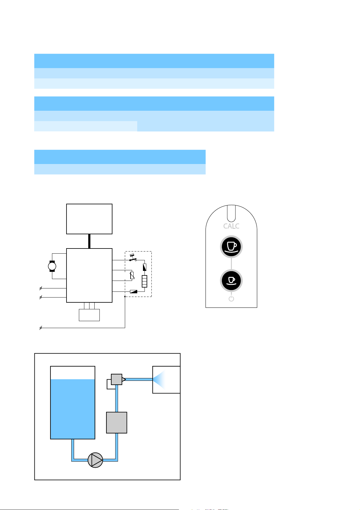
Electical diagram
UI
PCBA
Boiler
TCO
Pump
P
Main
PCBA
L
N
NTC
Fuse
-t
Fuse
User interface layout
Water level
sensor
E
Functional diagram
Water
Container
a
Pump
1-way valve
g
f
e
Boiler
d
cb
h
Brew
head
2-12
DISASSEMBLY- AND RE-ASSEMBLY ADVISE
Make sure the appliances cordset is disconnected from the mains!
To open the appliance, removal all detachable parts: Water container, driptray and cover, pod holder and collector.
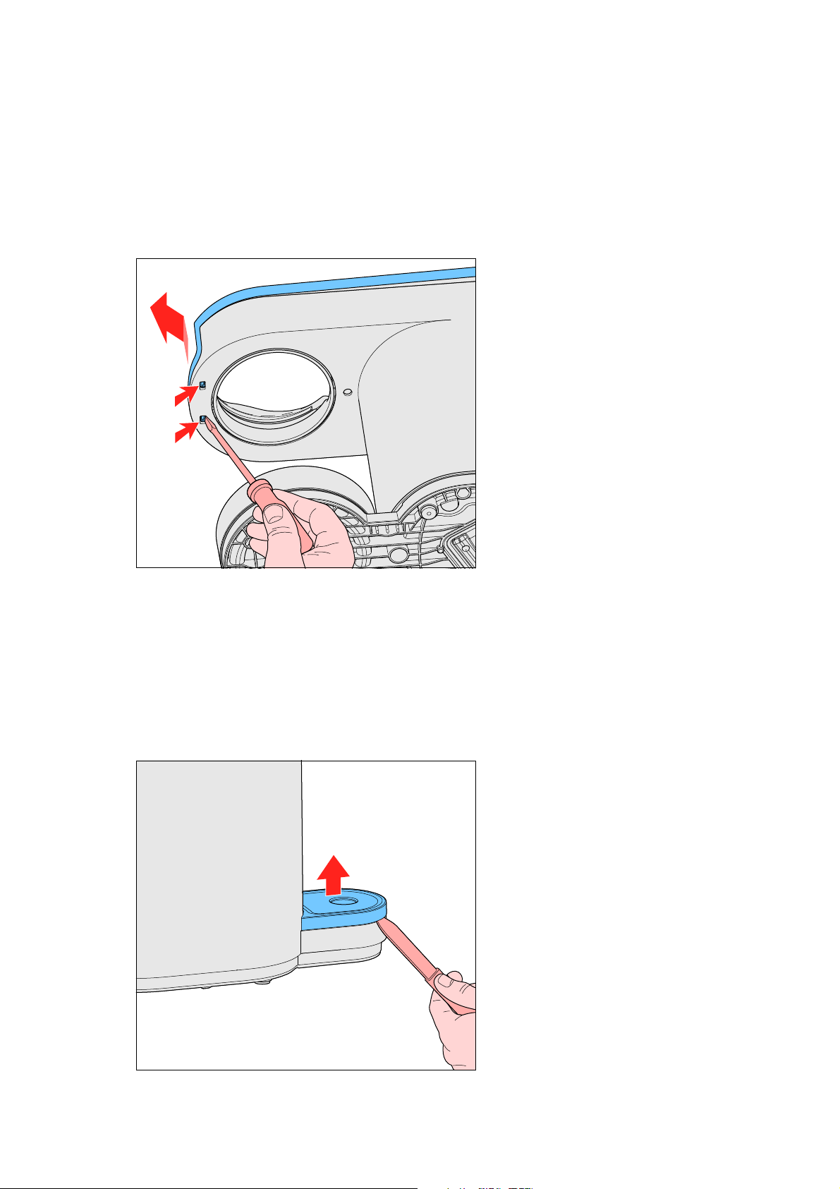
1. To reach the brew chamber.
1.1. Open the top cover.
To open to the top cover the brew chamber needs to be unlocked. Start at the back side of the top cover, using a
plastic tool, and trace along the parting line of the top cover, undoing all the snaps. There are two small snaps on the
front lower side of the brew chamber, undo them with a small athead screwdriver (No. 0)
HD7880/40 / HD7880/41
The top cover needs to be tilted forward to be removed. The at cable W from the main PCBA to the UI PCBA is
still attached to the User Interface panel, and can easily be unplugged.
The brew chamber can now be removed by unscrewing the two screws (B, T15), and undoing the hose connection
(g) from the one way valve.
To continue, rst remove the two screws (A, T15) from the bottom side of the appliance.
2. To reach internal components like Boiler or Pump.
2.1. Remove the back plate and undo the hose connection (g) from the one way valve (if not done so already).
To remove the back plate, use a plastic tool and trace the parting line of the back plate, undoing all the snaps.
The corrugated tube is still connected to the water container socket, and can easily be pulled off.
3-12
DISASSEMBLY- AND RE-ASSEMBLY ADVISE
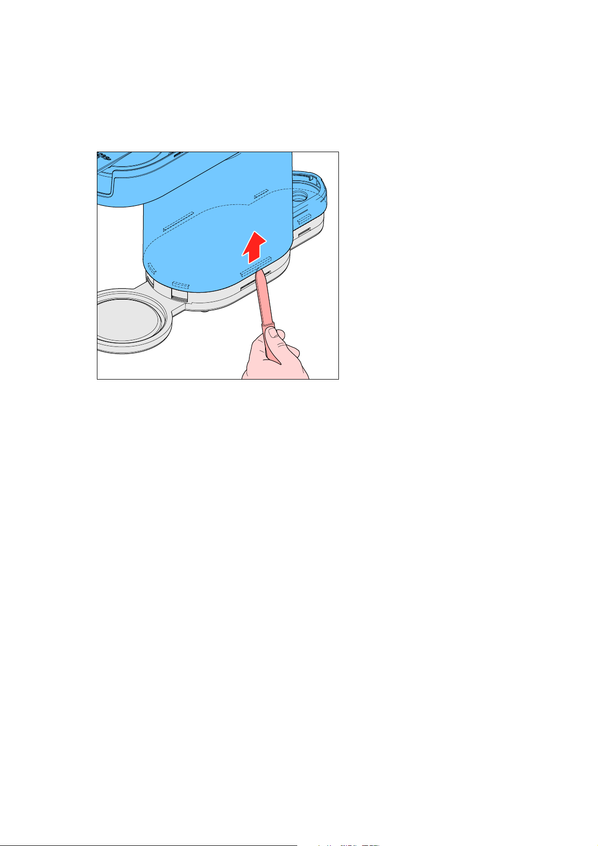
2.2. Remove the housing.
To remove the housing, start at the back side and undo the clicks on either side of the back plate, next continue on
either the left of right side and undo the click on the long lower side of the housing, next undo the snap on the
front round edge of the housing. Make sure that none of the snaps snap back. Repeat this procedure on the other
side of the appliance, working from back to front. Tip: leave a screwdrive or plastic tool in the area where the rst
front click was released, to prevent it snapping back.
1
HD7880/40 / HD7880/41
2
1
3
Remove the housing upwards from the rest of the appliance, but mind at cable running through the guide on the
inside of the housing and the water level sensor still connected to the inside of the housing.
You can now access the Boiler and Pump, to remove them, undo the electrical connections and hoses, and reinstall in the
reverse order. Any Ty-wrap that has been removed needs to be replaced by a new one, and tightened with the speci ed
forces.
3. To replace the PCBA.
3.1. Unscrew the inner frame.
Unscrew the two screws (C, T15) holding the inner frame in place, take special care to note the proper wire
routing, and make sure reinstalling the PCBA will be done in an identical way.
4-12
 Loading...