

Philips HD7870/81, HD7870/62, HD7870/60, HD7870/61, HD7870/10 Service Manual
...
Senseo Twist
HD7870/80
HD7870/81
Philips Consumer Lifestyle
Service Manual
PRODUCT INFORMATION
• This product meets the requirements regarding
interference suppression on radio and TV.
• After the product has been repaired, it should function
properly and has to meet the safety requirements as
officially laid down at this moment.
TECHNICAL INFORMATION
• Voltage : 220 - 240 V
• Frequency : 50 Hz
• Power consumption : 1450 W
• Standby power : 0.25 W
• Color setting : Chinese Fire
• Weight : 2,05 Kg
• Dimensions H x W x D
- Appliance : 31,5 x 24,9 x 30,8 cm
- F-Box : 36 x 29 x 29,5 cm
• Length of cord : 80 cm
• Contents water reservoir : 930 cc (ml)
ACCESSORIES
• CRP475/01 1-cup pod holder Black
• HD5015/01 2-cup pod holder Black
• CRP862/01 Drip tray cover Black
• CRP872/01 Collector
• CRP864/01 Water container small
• CRP869/01 Water container lid Deep Black
OPTIONAL (accessories)
• CRP865/01 Water container big (incl. bucket, optional
Britta Filter to be purchased separately)
• CRP866/01 Water container lid
(for Water container big)
Published by Philips Consumer Lifestyle Printed in the Netherlands © Copyright reserved Subject to modification
13/02

TECHNICAL INFORMATION
Volume adjustment
The PCB circuit board makes it possible to adjust the
volume output by means of pushing the one-cup and twocup user controls. How to adjust the volume output:
1. Make sure the boiler is lled properly, otherwise
perform ll procedure see DFU for instructions.
2. Switch appliance on and wait until the unit is ready to
brew.
3. Make sure a pod holder is placed, but without a Coffee
POD. (Only adjusting with plain water)
4. Place a cup on the drip tray cover and push the onecup button.
5. When the appliance has nished it is stabilized to
perform the volume adjustment.
6. Empty the cup, pod holder and push again for one cup
setting, measure the volume output with a graduated
beaker. In the table you can nd the requirements for
the minimum / maximum volume output cc/mL values
depending from the country version: (see Technical
speci cations)
7. Unplug the appliance from the mains.
8. Press the 1- and 2 cup button simultaneously and plug
the mains on.
9. When above step succeeded the LED will turn on
continuously.
10. Depending if the volume has to de- or increase you
have to push the one- or two cup button. Every time
you push the 1- or 2 cup button the LED will turn
off for 0.5 second (feedback to user) and the pump
time will be shortened or lengthened for 0.5 seconds
depending which button was pushed.
Pushing 1 cup button pump, time will be shorten
with 0.5 sec is approximately − 3.5 cc/mL (less coffee).
Pushing 2 cup button pump, time will be lengthen
with 0.5 sec is approximately + 3.5 cc/mL (more
coffee).
When the volume has to increase with 10 cc for
example, push the 2 cup button 3 times. The new value
will be stored when you switch the appliance off by
pushing the main switch (LED will turn off).
11. Turn appliance on again and brew one cup, measure the
volume. In case the volume is not within speci cation
repeat steps 6 - 11.
HD7870/80 / HD7870/81
Note:
Changing a newly installed PCBA (by default delivered with
General version settings) into a French or Spanish setting
requires a decrease of the pump time by 2,5 seconds
(or ve pushes of the 1-cup button).
2-12
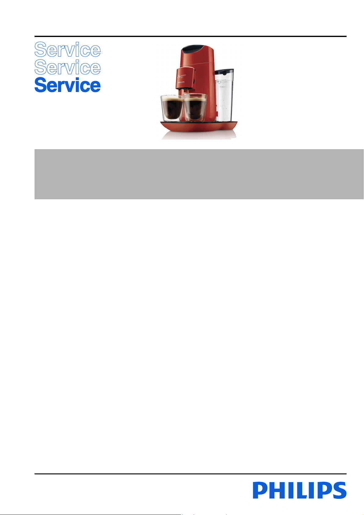
SCHEMATICS
HD7870/80 / HD7870/81
UI PCBA
On/Off button
1-cup button
2-cup button
Toggle button
On/Off LED
1-cup LED
2-cup LED
Toggle LED
Regular LED
Strong LED
Memory LED
Descale LED
Buzzer
Water level
sensor
Communi
cation
L
N
DISASSEMBLY- AND RE-ASSEMBLY ADVISE
Before you start dismantling! For your
!
safety be sure the plug is disconnected from
the mains! The product is designed for easy
access to the internal components. Make sure
that all accessories like tank, pod holder, drip
tray, spout and collector have been removed.
Pump
NTC
Water
Supply
System
TCO
Boiler
PCBA
Fuse
M
Fuse
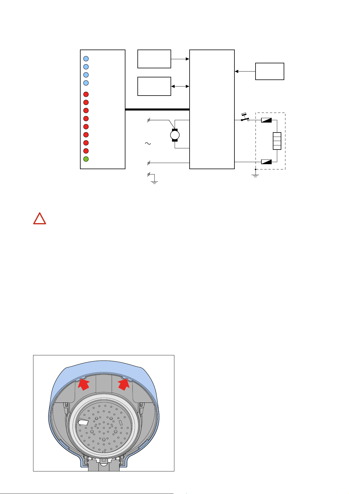
Caution, the hinge spring on the back side of the appliance may
come out when the brewhead lid cover is being removed.
When reinstalling it, mind your ngers as this is a strong spring.
To remove the boiler (24):
Caution the boiler may still be hot!
To remove the back cover (31):
Place the appliance facing its backside. Using a small
screwdriver remove screw cover (28) and unscrew both
screws A. You can now remove the back cover from the
appliance, please be aware that the Water level sensor (32)
is still attached to the back cover.
To remove the brewhead lid cover:
Place a screwdriver on the positions (see picture) and
work your way to the bottm. Please be aware that due
to the construction of the brewhead, the space inside is
limited. There is a chance Hose (a) will come off the pillar
when opening the brewhead (22).
• Remove the back cover.
• Disconnect the Hose (a) to the brewhead.
• Unhook the 3-way valve (27) from its seat on the
bottom of the brewhead.
• Unhook the boiler from the snap hook on the bottom of
the brewhead.
• Disconnect the following leads:
- (x) Boiler +
- (y) Boiler –
- (w) Earth
• Remove Hose (b) from the bottom side of the boiler.
The boiler will not drain as long as the 3-way valve is still
connected to the top. You can now safely remove the
boiler from the appliance.
Note:
Please note, after replacing the boiler the appliance has to be
restored to factory default. The lling procedure (cold ush),
known from the predecessor Senseo’s is no longer available
after the ush before rst use has been executed. When
the “restore to factory default” procedure is not carried out,
a new and empty boiler can be switched on, without having
the protection of the initial ush procedure, causing the
thermal fuses in the heating element to fail. After a boiler
replacement or drained system, carry out the “Boiler reset”
procedure! Then the initial ush procedure can be carried out.
3-12
DISASSEMBLY- AND RE-ASSEMBLY ADVISE
HD7870/80 / HD7870/81
To remove the brewhead assembly:
• Remove the back cover.
• Remove the boiler, or simply lay it aside.
• Use both thumbs to push the brewhead upwards; you
may need to tilt the brewhead forward to remove it
from the appliance.
To remove the PCB assembly (34):
• Remove the back cover
• Remove the boiler
• Remove the brewhead assembly
• Remove the Main PCBA cover (33)
• Disconnect the following leads:
- NTC ( at cable)
- Water level sensor ( at cable)
- (z) UI PCBA ( at cable)
- (s) Live
- (t) Pump
- (u) Neutral
- (v) Earth
• You can now unhook the snap hooks holding the PCBA
in place.
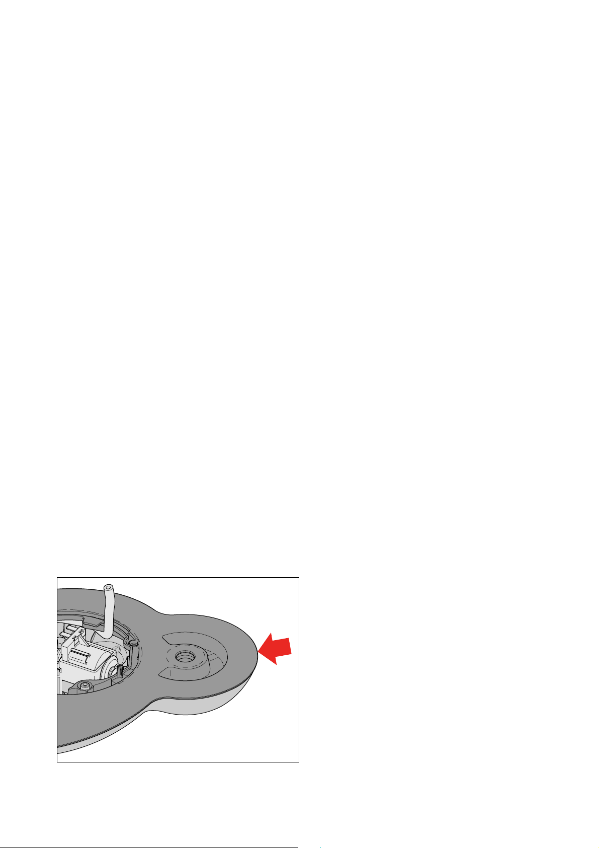
To access components located in the base of
the appliance (UI Panel, Pump, Water container
interface)
Open the Base:
• Remove the back cover
• Remove the boiler
• Remove the brewhead assembly
• Remove the Main PCBA cover (33)
• Remove the PCB assembly
• Unscrew the two screws (B) holding the Front housing
(23) in place. Remove the front housing
• Take the base of the appliance, using a small screw driver
start at the point indicated in the picture. Gently push
it between the tray panel assembly (36) and base plate
(41), the hidden snap should click open.
• Now use the screwdriver to trace around the edge of
the tray panel assembly and base plate until you reach
the position of the drip tray. Repeat the process for the
other side. All snap hooks will come undone.
Please note that the water container interface is still
connected to the tray panel assembly and to the pump on the
base plate
To access the capacitive UI PCBA:
• Remove the back cover
• Remove the boiler
• Remove the brewhead assembly
• Remove the Main PCBA cover (33)
• Remove the PCB assembly
• Unscrew the two screws (B) holding the Front housing
(23) in place. Remove the front housing
• Open the Base
• Turn the Tray panel assembly upside down and open the
clicks of the UI PCBA Cover
• Here you will find:
- UI PCBA (38)
- UI Panel frame
- Light distributor
Descaling
Descaling is an important element in Senseo maintenance.
It should be done at least once every 3 months, up to
6times a Year! This will prolong the life of your appliance
and will guarantee optimal brewing results for a long time.
Use the correct descaling agent. Only citric acid-based
descalers are suitable for descaling the SENSEO
This type of descaler descales the appliance without
damaging it. For the correct amount, see the instructions
in the packaging of the descaler.
We advise you to use the special SENSEO® Descaler
(HD7011 or HD7012). Read the instructions on the
package of the descaling agent. Never use a descaling agent
based on mineral acids such as sulphuric acid, hydrochloric
acid, sulphamic acid and acetic acid (e.g. vinegar). These
descaling agents may damage your SENSEO® coffee
machine. Follow the steps in the section headed “Descale
the appliance” see DFU (Direction for Use manual).
®
machine.
• Undo the two click connections visible on the bottom
side of the appliance.
4-12
 Loading...