

Philips HD7853/60, HD7853/61, HD7853/62 Service Manual
Coffee Maker Senseo “Latte Select”
HD7853/60
HD7853/61
HD7853/62
Philips Consumer Lifestyle
Service Manual
PRODUCT INFORMATION
• This product meets the requirements regarding
interference suppression on radio and TV.
• After the product has been repaired, it should function
properly and has to meet the safety requirements as
officially laid down at this moment.
TECHNICAL INFORMATION
• Voltage : 220 - 240 V
• Frequency : 50 - 60 Hz
• Power consumption : 2650 W
Boiler : 1450 W
Steam heater : 1200 W
Cappuccino Volume (cc) Weight (g)
cc max. (g) min. (g) (°C)
• Standby power (switched off) : 1 W
• Standby power : 30 W
(switched on 30 min) (room temperature)
• Pressure Coffee system : 1.6Bar
• Pressure Steam system : 1 Bar
• Contents water reservoir : 1200 cc/mL
• Contents milk reservoir : 120 cc/mL
• Auto shut off : 30 min
• Colour setting : Deep Black
• Sap coding : HD7853/60
HD7853/61
HD7853/62
Indication temperature for chosen Coffee/Milk receipe
very depended from milk inlet temperature.
All versions
Published by Philips Consumer Lifestyle Printed in the Netherlands © Copyright reserved Subject to modification
11/07
159 15
160 130
63
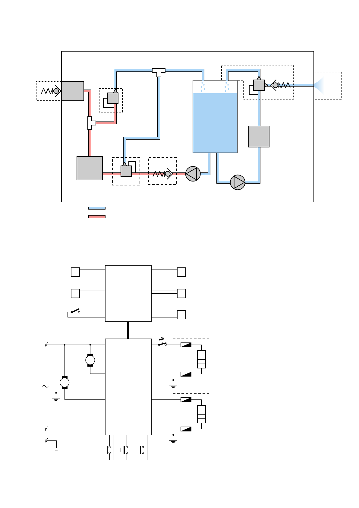
Build up: Water and Steam circuit
Steam
ll
o
seal
Reflux
valve in
milk
container
jj
kk
ii
hh
Venting
valve
HD7853/60 /61 /62
mn
l
p
f
Three-way
valve with
Water
Container
Check valve
e
Boiler
g
h
Brew
Chamber
Legend: Low pressure tube
Electrical circuit
Temp. sensor
boiler
Temp. sensor
Thermo block
Lid close
detection
switch
gg
Thermo
block
a - p
aa - ll
k
Check valve
ff
ddee
Overpressure
valve
High pressure tube
Low pressure connections
High pressure connections
W
CONNECTION
PCB
X
U
Y
S
V
T
d
ia
bbcc
aa
j
cb
Steam
pump
Water level
sensor
Milk tank
detection
sensor
Descale tool
detector
Water pump
Inside the appliance
TCO
L
Pump
M
Steam
M
pump
N
CONTROL
PCB
Push buttons
Boiler
Fuse
Fuse
Thermo block
Fuse
Fuse
2-11
DISASSEMBLY- AND RE-ASSEMBLY ADVISE
HD7853/60 /61 /62
Remove back cover.
• Remove screws (T15) from the back cover.
• Remove valve outlet.
• Start at the upper side of the back cover and stick a
screwdriver between the back cover and lid cover and
gently pull the back cover from the appliance so that a little
chink between back cover and lid becomes visible.
• Put the screwdriver into the 2 rectangular holes (snap
locks) at the back and gently pull the screwdriver such away
that the lips of the snap locks are bent outwards.
• If both clicks positions are loose, it is possible to remove
the back cover.
• Reassemble follow steps backwards.
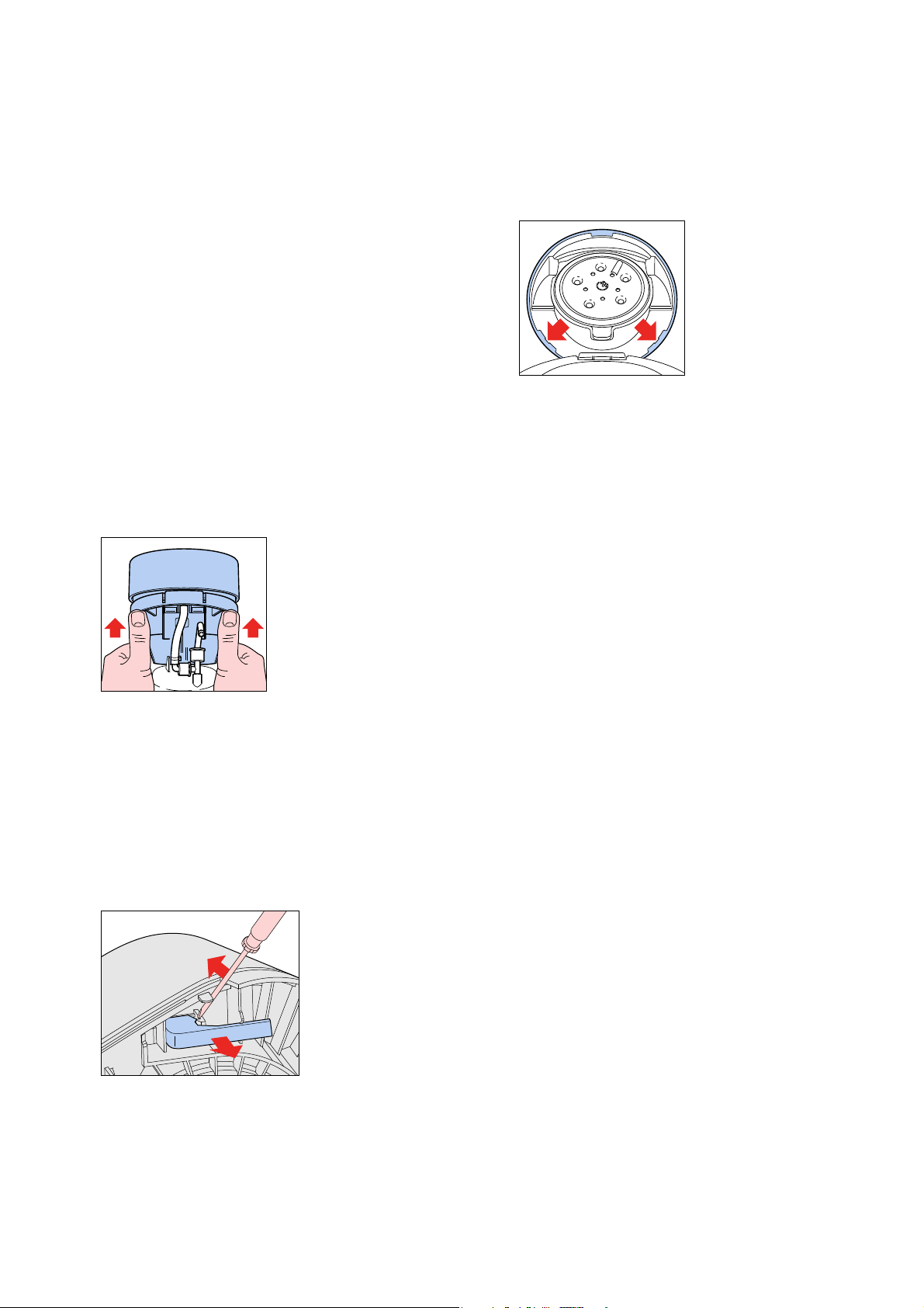
Remove brew chamber:
Removing Brew chamber head handle as follows:
• Remove boiler from the snap lock position of the brew
chamber.
• Gently lift the backside (see picture) of the brew chamber
up and unhook the two snap locks on front with help of a
screw driver.
Remove brew chamber cover to reach user
interface PCB.
• To remove the brew chamber lid cover place the
screwdriver on the positions (see picture) and lift the cover
over the snap locks on both positions.
• The cover lid can now be lifted a little.
• Remove the complete cover by unlocking the pushrod from
the brew chamber.
• The user interface PCB can be removed by unscrewing
3 screws (T8)
• Reassemble follow steps backwards.
Removing the “de-scaling Hall sensor”
detector / steam connection
• Remove connection PCB + PCB cover.
• Remove 3 way valve and electronic connector (U) from the
connection PCB.
• Reassemble follow above steps backwards.
Remove the “lid closed” detection micro
switch.
Disassemble brewing head.
• Unlock the snap lock which is holding the micro switch
assembly. (see picture for detail)
• To be able to remove the Hall sensor, first unhook the spout
out of the housing.
• Hall sensor assy can be taken out.
• To disconnect the steam connector rotate it clockwise and
pull out of the spout.
To reach the components like pump, PCB,
steam heater placed on the base.
• First remove back cover, brew chamber, 3-way valve, steam
pump and boiler.
• Remove the 4 Torx T15 screws (two at the base and two at
the housing part.
• Bend the 2 click snap locks with a screwdriver (see base),
the housing can now be removed.
• To remove the rest of the housing unlock the 4 snap locks
at the base and gently pull of the front cover.
• To reassemble follow above steps backwards.
OPTIONAL (accessories)
• No specific issues
• Gently pull out the switch assembly.
• Reassemble follow above steps backwards.
3-11
REPAIR INSTRUCTION
Descaling
Descaling is an important element in Senseo maintenance.
It should be done at least once every 3 months, up to 6 times
a Year! This will prolong the life of your appliance and will
guarantee optimal brewing results for a long time.
Use the correct descaling agent. Only citric acid-based
®
descalers are suitable for descaling the SENSEO
machine.
This type of descaler descales the appliance without damaging
it. For the correct amount, see under ‘Descaling procedure’
below.
Each descaling mixture can be used only once. After use, the
descaling mixture is no longer active. We advise you to use
®
the special SENSEO
Descaler (HD7006).
Read the instructions on the package of the descaling agent.
Never use a descaling agent based on mineral acids such as
sulphuric acid, hydrochloric acid, sulphamic acid and acetic
acid (e.g. vinegar). These descaling agents may damage your
SENSEO® coffee machine.
Follow the steps in the section headed “Descale the appliance”
see DFU (Direction for Use manual).
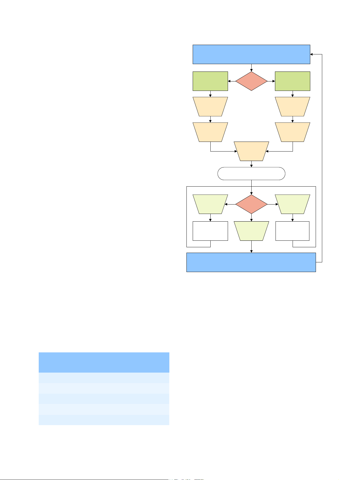
Press 1-cup & 2-
cup button
simultaneously
Do NOT
insert Milk
Container
HD7853/60 /61 /62
Start -
Unplugged appliance
Adjust what?Black coffee volume
Plug the
appliance
into the
mains
If above steps were successful,
1-cup, On/Off & 2-cup button will be lit
Coffee volume in
cappuccino recipe
Press 1-cup & 2-
cup button
simultaneously
Insert Milk
Container
Volume adjustment
The PCB circuit board makes it possible to adjust the volume
output by means of pushing the one-cup and two-cup user
controls.
How to adjust the volume output:
1. Be sure the boiler is lled properly, other wise perform ll
procedure see DFU for instructions.
2. Switch appliance on and wait until the unit is ready to brew.
3. Choose the setting of which you want to adjust the volume
4. Be sure a pod holder is placed, but without a Coffee
POD. (Only adjusting with plain water)
5. Place a cup on the drip tray cover.
Press the 1-cup button once to measure the black coffee
volume, press the 1-cup button twice to measure the
coffee volume in a cappuccino.
6. When the appliance has nished it is stabilized to perform
the volume adjustment.
7. Empty the cup, podholder and push again for one cup
setting, measure the volume output with a graduated
beaker. In the table you can nd the requirements for
the minimum / maximum volume output cc/mL values
depending from the country version:
One-cup setting, Including Pod holder, water spec.
(Without Coffee pod)
1-cup button 2-cup button
Decrease
pump time with
0,5 sec. 3,5mL/cc
Press what?
On/Off
button
Store settings
Increase
pump time with
0,5 sec. 3,5mL/cc
8. Turn appliance on again and brew one cup, measure the
volume. In case the volume is not within speci cation
repeat step 7.
9. End.
Min. water cc/mL Max. water cc/mL
General 125 141
France 104 120
Spain 65 81
Cappuccino 65 81
4-11
 Loading...