

Page 1

Subwoofer Mini Hi-Fi System
�
FWM608
-/12/05
CONTENTS
Technical specification ..................................................................1-2
Service measurement setup..........................................................1-3
Service aids .................................................................................1-4
Instructions on CD playability ................................................2-1..2-2
Block diagram ................................................................................3-1
Wiring diagram ..............................................................................4-1
Disassembly diagram............ ................................................5-1..5-2
Main board
Circuit diagram ..................................................................6-1..6-2
Layout diagram ..................................................................6-3..6-4
Tuner board
Circuit diagram .........................................................................7-1
Layout diagram .........................................................................7-2
Front board
Circuit diagram .........................................................................8-1
Layout diagram ..................................................................8-2..8-3
AMP board
Circuit diagram .........................................................................9-1
Layout diagram .........................................................................9-2
CD Board
Circuit diagram. ......................................................................
Layout diagram ..............................................................
MCU Board
Circuit diagram. ......................................................................
Layout diagram .......................................................................
Exploded view diagram ...............................................................12-1
Mechanical parts list ...........................................................12-2..12-3
Electrical parts list...............................................................13-1..13-2
10-1
10-2..10-3
11-1
11-2
©
Copyright 2009 Philips Consumer Electronics B.V. Eindhoven, The Netherlands
All rights reserved. No part of this publication may be reproduced, stored in a retrieval
system or transmitted, in any form or by any means, electronic, mechanical, photocopying,
or otherwise without the prior permission of Philips.
Published by LX 0946 Service Audio Subject to modification
Version 1.0
3141 785 34530
Page 2
Total output power 600W RMS
Frequency response 60 - 16kHz
Signal-to- noise ratio >67dB A (IEC)
Aux input 500mV/700mV
Disc
Laser type Semiconductor
Disc diameter 12cm/8cm
Support disc CD-DA, CD-R, CD-
RW, MP3-CD, WMA-
CD
Audio DAC 24Bits / 44.1kHz
Total harmonic
distortion <1.5%
Frequency response 60Hz -16kHz (44.1kHz)
S/N ratio >75dBA
Tuner
Tuning range FM: 87.5 - 108MHz;
MW (AM):
531 - 1602kHz
Number of presets 40
FM 75ohm wire
MW (AM) Loop antenna
Speakers
Speaker Impedance 3ohm
Woofer 2 x 5.25”
Tweeter 2 x 1.75”
Dimensions
(W x H x D) 225 x 430 x 275mm
Weight 4.928kg each
Subwoofer
Speaker impedance 6ohm
Speaker driver 8”
Output power 180W
Dimensions ( W x H
x D) 274 x 430 x 340mm
Weight 6.747kg
General information
AC power 220 - 230V, 50Hz
Operation power
consumption 130W
Standby power
consumption <20W
Eco Standby power
consumption <1W
USB direct Version 2.0/1.1
Dimensions
Main Unit (W x H x D) 265 x 345 x 382mm
Weight (without
speakers) 8.505kg
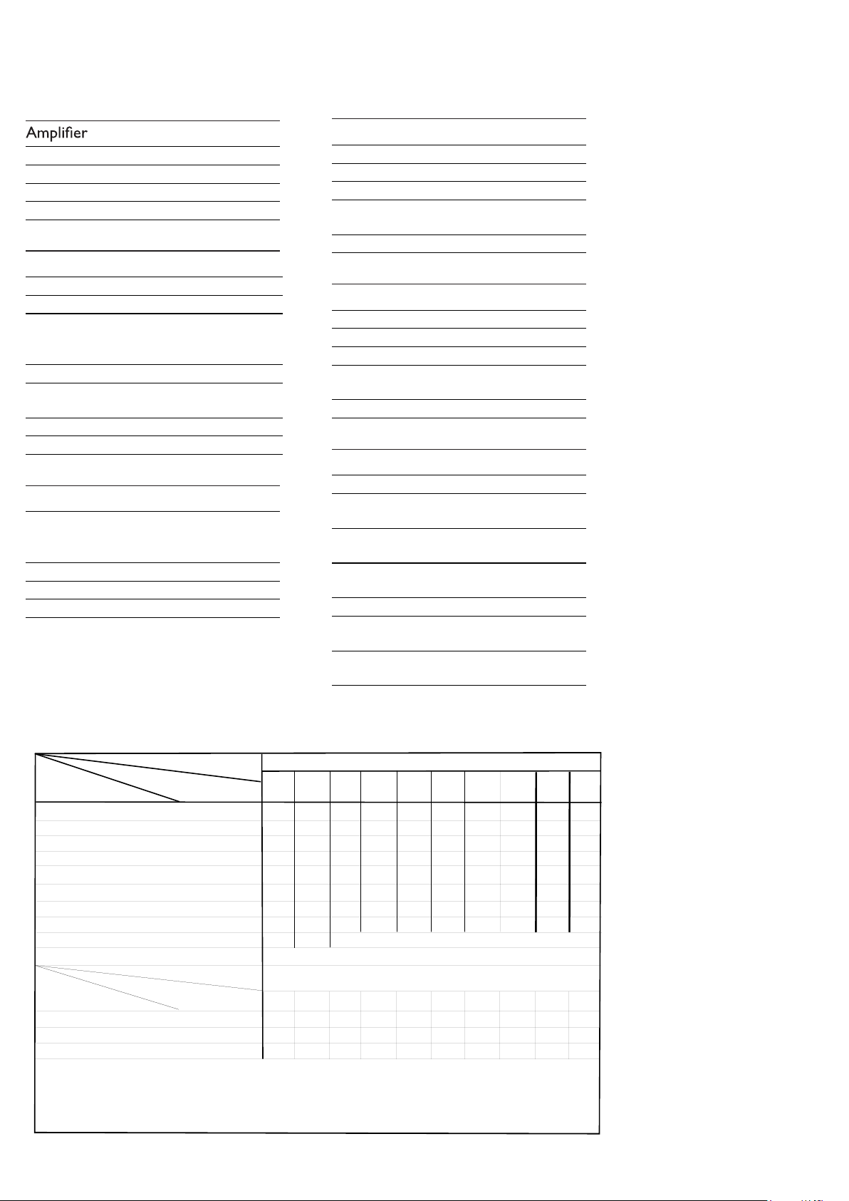
TECHNICAL SPECIFICATION
Type /Versions:
Features
Board in used:
FWM608
Service policy
DISPLAY(FRONT) BOARD
MAIN BOARD
* TIPS : C -- Component Lever Repair.
M -- Module Lever Repair
√ -- Used
/05 /12
/55
89/16/37/
Feature diffrence
RDS & DAB
VOLTAGE SELECTOR
ECO STANDBY - DARK
√
Type /Versions:
/05 /12
/55
89/16/37/
VERSION VARIATION
39/
39/
C
C
√
AMP BOARD
MCU BOARD
CD BOARD
C
M
M
FWM608
√
C
C
√
C
M
M
TUNER BOARD
M M
1 - 2
Page 3

e
MEASUREMENT SETUP
Tuner FM
1-3
Bandpass
LF Voltmeter
e.g. PM2534
RF Generator
e.g. PM5326
DUT
250Hz-15kHz
e.g. 7122 707 48001
Ri=50:
S/N and distortion meter
e.g. Sound Technology ST1700B
Use a bandpass filter to eliminate hum (50Hz, 100Hz) and disturbance from the pilottone (19kHz, 38kHz).
Tuner AM (MW,LW)
RF Generator
e.g. PM5326
Ri=50:
DUT
Frame aerial
e.g. 7122 707 89001
Bandpass
250Hz-15kHz
e.g. 7122 707 48001
LF Voltmeter
e.g. PM2534
S/N and distortion meter
e.g. Sound Technology ST1700B
To avoid atmospheric interference all AM-measurements have to be carried out in a Faraday´s cage.
Use a bandpass filter (or at least a high pass filter with 250Hz) to eliminate hum (50Hz, 100Hz).
CD
Use Audio Signal Disc
(replaces test disc 3)
DUT
L
R
SBC429 4822 397 30184
S/N and distortion meter
e.g. Sound Technology ST1700B
LEVEL METER
e.g. Sennheiser UPM550
-
Recorder
Use Universal Test Cassette CrO2 SBC419 4822 397 30069
or Universal Test Cassette
LF Generator
e.g. PM5110
Fe SBC420 4822 397 30071
DUT
L
R
S/N and distortion met
e.g. Sound Technology ST170
LEVEL METER
e.g. Sennheiser UPM550
with FF-filter
Page 4

SERVICE AIDS
1-4
GB
All ICs and many other semi-conductors are
susceptible to electrostatic discharges (ESD).
Careless handling during repair can reduce life
drastically.
When repairing, make sure that you are
connected with the same potential as the mass
of the set via a wrist wrap with resistance.
Keep components and tools also at this
potential.
WARNING
GB
Safety regulations require that the set be restored to its original
condition and that parts which are identical with those specified,
be used
Safety components are marked by the symbol
!
.
ESD
CLASS 1
LASER PRODUCT
Lead free
Page 5

INSTRUCTIONS ON CD PLAYABILITY
Customer complaint
"CD related problem"
Set remains closed!
check playability
1
2 - 1
playability
ok ?
Y
Play a CD
for at least 10 minutes
check playability
playability
ok ?
Y
N
"fast" lens cleaning
check playability
playability
ok ?
N
3
N
Y
For flap loaders (= access to CD drive possible)
cleaning method
4 is recommended
add Info for customer
"SET OK"
2
return set
1 - 4 For description - see following pages
Exchange CDM
Page 6

INSTRUCTIONS ON CD PLAYABILITY
2 - 2
1
PLAYABILITY CHECK
For sets which are compatible with CD-RW discs
use CD-RW Printed Audio Disc....................7104 099 96611
TR 3 (Fingerprint)
TR 8 (600µ Black dot) maximum at 01:00
• playback of these two tracks without audible disturbance
playing time for: Fingerprint
Black dot from 00:50 to 01:10
• jump forward/backward (search) within a reasonable time
For all other sets
use CD-DA SBC 444A..................................4822 397 30245
TR 14 (600µ Black dot) maximum at 01:15
TR 19 (Fingerprint)
TR 10 (1000µ wedge)
• playback of all these tracks without audible disturbance
playing time for: 1000µ wedge 10seconds
Fingerprint 10seconds
Black dot from 01:05 to 01:25
• jump forward/backward (search) within a reasonable time
10seconds
4
LIQUID LENS CLEANING
Before touching the lens it is advised to clean the
surface of the lens by blowing clean air over it.
This to avoid that little particles make scratches on
the lens.
Because the material of the lens is synthetic and coated
with a special anti-reflectivity layer, cleaning must be done
with a non-aggressive cleaning fluid. It is advised to use
“Cleaning Solvent
The actuator is a very precise mechanical component and
may not be damaged in order to guarantee its full function.
Clean the lens gently (don’t press too hard) with a soft and
clean cotton bud moistened with the special lens cleaner.
The direction of cleaning must be in the way as indicated in
the picture below.
2
CUSTOMER INFORMATION
It is proposed to add an addendum sheet to the set which
informs the customer that the set has been checked
carefully - but no fault was found.
The problem was obviously caused by a scratched, dirty or
copy-protected CD. In case problems remain, the customer
is requested to contact the workshop directly.
The lens cleaning (method 3) should be mentioned in the
addendum sheet.
The final wording in national language as well as the printing
is under responsibility of the Regional Service Organizations.
Page 7

BLOCK DIAGRAM
3-1 3-1
3CDC CD Loader
PICK-UP MECHA
SANYO : DA-11VF
CD PCB BOARD
MCU PCB BOARD
RECORD TIME
(74LVC2G04)
SDRAM
16Mbit
NOR FLASH
SI636165
4 CH
MOTOR DRIVER
(BA5826)
ROHM
RF AMP+SSP+DSP
(BU9543)
MUX
74VC157
ADC
WMA8781
MCS LOGIC BX8805
MP3/WMA En/De + MCU +USB/CARD
PLL Tuner
Si4730/4731
TIME/CLOCK(H
T1381)
Spectrum
analyzers
LED controller
for Light Box
(May use)
USB SOCKET
DISPLAY
VFD
KEY BOARD
Port Expander
74HC4094
MAIN PCB BOARD
AMP PCB BOARD
SUBWOFFER
TDA8920
2
amp
SOUND CONTROL
SW+VOL+EQ
(TDA7468 )
1
AUX/MP3-LIN
Karaoke(CD3699)
High power
AMP
TDA8920
Mid power amp
TDA8920
1
1
L
R
L
R
Page 8

WIRING DIAGRAM
4-1 4-1
USB SOCKET BOARD
J907
J904
J906
VFD PCB BOARD
J915 J903
J901
CW104
CW102
MCU PCB BOARD
CW105
CW101CW103
JCN303
CN612
CN601
CN604
MAIN PCB BOARD
CN607
CN611CN903
CN603
CN602
AMP PCB BOARD
CON302
CON301
CON521
CN504
CON589
CD PCB BOARD
CN551
3CDC MOTOR BOARD
CN501
CN505
CLOSE/OPEN MOTOR
Page 9

5-1 5-1
DISMANTLING INSTRUCTIONS
Disman tling of the CDC Modu le and Front Panel
1)Loos en 17 screws to remov e the Cover Top of the set.
4)Loos en 2 screws A and 2 screw s B to remove the
CDC Modu le as indicated.
5)Remo ve 2 screws at the bott om to separate the
Front Panel Assembly from t he Plate Bottom.
2)Slid e out the CDC Tray as shown in the diagram b elow
with the help of a flat head scre w driver.
Front View CDC
Sliding Out The CDC Tray
Remove CDC Module
3)Remo ve the Cover Tray CDC a s indicated .
Remove Cover Tray CDC
Page 10

5-2 5-2
DISMANTLING INSTRUCTIONS
Dismantling of Rear Portion
1)Remove 3 screws C as indicated to loosen the Tuner Board.
2)Remove 6 screws D&G as indicated to loosen the MAIN Board.
3)Remove 8 screws E&H as indicated the AMP Board.
4)Remove 3 screws F as indicated to loosen the Bottom Cabinet.
C
D
E
F
Dismantling of the PCB Board
1)Remove 14 screws I as indicated to loosen the KEY1 Board.
2)Remove 11 screws J as indicated to loosen the KEY2 Board.
3)Remove 3 screws K as indicated the USB SOCKET&LINE IN Board.
G
H
H
I
J
K
Page 11

CIRCUIT DIAGRAM-MAIN BOARD
6-1 6-1
Page 12

CIRCUIT DIAGRAM-MAIN BOARD
POWER SUPPLY SECTION
6-2 6-2
Page 13

LAYOUT DIAGRAM-MAIN BOARD
TOP SIDE
6-3 6-3
Page 14

LAYOUT DIAGRAM-MAIN BOARD
BOTTOM SIDE
6-4 6-4
Page 15

CIRCUIT DIAGRAM-TUNER BOARD
7-1 7-1
Page 16

LAYOUT DIAGRAM-TUNER BOARD
7-2 7-2
Page 17

CIRCUIT DIAGRAM-FRONT BOARD
8-1 8-1
Page 18

LAYOUT DIAGRAM-FRONT BOARD
TOP SIDE
8-2 8-2
Page 19

LAYOUT DIAGRAM-FRONT BOARD
BOTTOM SIDE
8-3 8-3
Page 20

CIRCUIT DIAGRAM-AMP BOARD
9-1 9-1
Page 21

LAYOUT DIAGRAM-AMP BOARD
9-2 9-2
Page 22

LAYOUT DIAGRAM-CD BOARD
TOP SIDE
10-2 10-2
Page 23

CIRCUIT DIAGRAM-CD BOARD
10-1 10-1
Page 24

LAYOUT DIAGRAM-CD BOARD
BOTTOM SIDE
10-3 10-3
Page 25

CIRCUIT DIAGRAM-MCU BOARD
11-1 11-1
Page 26

LAYOUT DIAGRAM-MCU BOARD
11-2 11-2
Page 27

SET EXPLODED VIEW
12-1 12-1
Page 28

MECHANICAL PARTSLIST
0008 996520035926 PCBA-CD
0009 996520035732 MCU BOARD ASSY
0003 996520035724 TUNER BOARD ASSY
0004 996510030589 3CD MECA DA11VF (NO PCB-A)
0082 996510030587 CD MECHANISM(SANYO) DA11VZSS
102 996510014310 MAGNET 27x16x4mm 546g
103 996510000439 PHILIPS LOGO
110 996510014336 SPRING-GUIDING
111 996510014337 SPRING-DISC
154 996510020809 VOL KNOB COVER
201 996510021399 FRONT CABINET
205 996510016105 FOOT HOLDER
206 996510017810 3CDC DOOR
207 996510017811 LEFT PANEL AROUND VOL
209 996510017812 RIGHT PANEL AROUND VOL
210 996510016109 TOP COVER
211 996510016110 LEFT COVER
212 996510016111 RIGHT COVER
213 996510016112 BOTTOM COVER
214 996510017813 TOP CD BUTTON
215 996510016115 ALBUM BUTTON
216 996510020806 USB DELETE BUTTON
217 996510016116 TITLE BUTTON
218 996510016117 STOP BUTTON
219 996510016118 PLAY BUTTON
220 996510016119 MODE BUTTON
221 996510016120 PROGRAM BUTTON
222 996510016121 POWER BUTTON
223
996510020801
VOL KNOB
224 996510020799 MAX SOUND BUTTON
225 996510016124 CLUSTER BUTTON
226 996510017815 USB REC BUTTON
227 996510020794 JAZZ BUTTON
228 996510020793 TECHNO BUTTON
229 996510016128 DDB BUTTON
230 996510017818 IS-VAC BUTTO N
231 996510017819 LIGHT-DISPLAY BUTTON
232 996510020805 MIC KNOB
234 996510016131 IR LENS
235 996510016132 POWER LIGHT GUIDE
236 996510016133 VOL LIGHT GUIDE
237 996510016142 VOL RING
238 996510016134 DBB LIGHT GUIDE
239 996510017820 MAX BUTTON LIGHT GUIDE
242 996510030592 MIDDLE STRAP SOUND BUTTON
243 996510030583 DISPLAY TOP BAR
244 996510016139 MIDDLE STRAP L
245 996510016140 MIDDLE STRAP R
246 996510020803 MIDDLE STRAP TOP BUTTON
248 996510016143 USB RING
12 - 2
Page 29

MECHANICAL PARTSLIST
8001 994000004487 16P FFC 1MM L=170MM
8003 994000004457 5P FFC L=200MM(AA)
J002 996510015477 26P FFC.1.25mm L=80mm
J013 996500039522 4P FFC CABLE 1.25mm L=270mm
J014 996510016102 9P FFC.1.25mm L=80mm
J015 994000002431 FFC CABLE 10P L=120MM
J016 996510015486 18P FFC.1.25mm L=150mm
J017 996510016103 14P FFC.1.25mm L=180mm
J018 996500040407 18P FFC 1.25mm L=130mm
T001
!
996510030588 TRANS. EI86xS65 230V
ACCESSORIES
0006 996510030582 REMOTE CONTROL
J010
!
994000003633 AC CORD SET VDE APP 6FT (only for -/12)
J010
!
994000000374 AC CORD SET VDE 6FT (only for -/05)
J011 996510009429 FM ANT (GREY) 1.5M CE/75
J012 996510002089 CONN. CORD 3.5 ST/PLUGx2 500mm
S001 996510030584 SPK BOX(L+R)+SUBWOOFER BOX
Note: Only these parts mentioned in the list are
normal service parts.
12- 3
Page 30

ELECTRICAL PARTSLIST
MAIN BOARD ASSEMBLY
C910 996510022979 E.CAP 4700UF 25V +-20% 85C
C927
!
994000001225 SAFETY CAP 275V 0.22UF -20%
CN606 994000001221 V/RCA JACK 2P
D601 996510012557 RECTIFIER DIODE 1N5819
F901
!
994000001223 FUSE RADIAL T5A 250V
F902
!
996510002426 CERAMIC FUSE 3.9x10.5mmW
F903
!
996510002426 CERAMIC FUSE 3.9x10.5mmW
F904
!
994000000586 GLASS FUSE W/LEAD 3.15A/250V
F905
!
994000001229 FUSE RADIAL T200MA/250V
IC601 996510005250 IC TDA7468D
IC602 994000001201 IC NJM4556AM
IC603 996510018852 IC UTC7808
IC606 996510018962 IC UTC7805
IC607 994000001247 IC HEF4094BT
IC608 994000001247 IC HEF4094BT
IC609 994000001201 IC NJM4556AM
J001 996510014304 AC SOCKET UL APP
Q315 996510006580 SMD TRANSIST BC847C
Q605 994000004145 TRANSISTORS B772Y (160-320)
Q609 994000004145 TRANSISTORS B772Y (160-320)
Q906 996510030591 TRANSISTOR BC327-40
Q907 996510030591 TRANSISTOR BC327-40
Q908 996510025141 TRANSISTOR BC547B
Q909 996510025141 TRANSISTOR BC547B
RL901 996500039818 RELAY ME-7-006-HSL DC6V AC10A
T001
!
996510000853 TRANSF. 230V T28-0622022-00
U901
996510016090
IC AP1117E33L-13
AMP BOARD ASSEMBLY
C916 996510005247 E.CAP 4700UF 50V +-20% 85C
C917 996510005247 E.CAP 4700UF 50V +-20% 85C
JSPK1 996510016371 SPK JACK
JSPK2 996510016097 SPK JACK 8P PT-24V11A
Q309 996510006580 SMD TRANSIST BC847C
Q310 996510006581 SMD TRANSISTORS BC857C
Q311 996510010292 SMD TRANSISTORS MMBT3904
Q312 996510010292 SMD TRANSISTORS MMBT3904
Q901 996510006580 SMD TRANSIST BC847C
Q902 994000004545 TRANSISTORS BUK9507-30B
Q903 994000004545 TRANSISTORS BUK9507-30B
Q904 996510006581 SMD TRANSISTORS BC857C
Q905 996510006581 SMD TRANSISTORS BC857C
U301 996510003980 IC TDA8920(SOT566-3) 2X100W
U302 996510003980 IC TDA8920(SOT566-3) 2X100W
U304 996500042457 IC HEF4013BT
U305 996500042456 IC 74HCT04D SOP14
U306 996510003980 IC TDA8920(SOT566-3) 2X100W
U307 996500039808 IC SM LM324D
U308 994000001201 IC NJM4556AM
Y301 996500042460 CERAMIC RESONATOR 600KHz
Y302 996500042461 CERAMIC RESONATOR 700KHz
13 - 1
Page 31

ELECTRICAL PARTSLIST
DISPLAY(FRONT) BOARD ASSEMBLY
D909 996510000438 LED LAMP
D910 996510000438 LED LAMP
D911 996510000438 LED LAMP
D912 996510000438 LED LAMP
D914 996510000438 LED LAMP
D915 996510000438 LED LAMP
D919 996510000438 LED LAMP
D920 996500042443 LED LAMP 2x5x7mm(S.BLUE)
D923 996510000438 LED LAMP
D924 996510000438 LED LAMP
FTD901 996510016092 VFD DISPLAY
J004 996510030586 TERMINAL WIRE L=150mm
J905 996510000344 USB SOCKET
J908 994000001244 V/PHONE JACK 3.5MM
J909 994000001244 V/PHONE JACK 3.5MM
J911 994000001244 V/PHONE JACK 3.5MM
P901 994000000325 OPTIC SENSER (OPTO..)
Q909 996510008369 TRANSISTORS MMBT8050D (SOT23)
Q912 996510000315 SMD TRANSISTORS BC807-25
Q971 996510006601 SMD TRANSIST BC857B
Q981 996510006601 SMD TRANSIST BC857B
SW901 994000001243 TACT SWITCH
SW902 994000001243 TACT SWITCH
SW903 994000001243 TACT SWITCH
SW904 994000001243 TACT SWITCH
HCTIWSTCAT342100000499019WSHCTIWSTCAT342100000499509WS
SW906
994000001243
TACT SWITCH
SW911
994000001243
TACT SWITCH
HCTIWSTCAT342100000499219WSHCTIWSTCAT342100000499709WS
HCTIWSTCAT342100000499319WSHCTIWSTCAT342100000499809WS
HCTIWSTCAT342100000499419WSHCTIWSTCAT342100000499909WS
SW915 994000001243 TACT SWITCH
SW916 994000001243 TACT SWITCH
SW917 994000001243 TACT SWITCH
SW918 994000001243 TACT SWITCH
SW919 994000001243 TACT SWITCH
SW920 994000001243 TACT SWITCH
SW921 994000001243 TACT SWITCH
SW922 994000001243 TACT SWITCH
SW923 994000001243 TACT SWITCH
SW924 994000001243 TACT SWITCH
SW925 994000001243 TACT SWITCH
SW926 994000001243 TACT SWITCH
SW927 994000001243 TACT SWITCH
SW928 994000001243 TACT SWITCH
SW929 994000001243 TACT SWITCH
SW930 994000001243 TACT SWITCH
U901 996510016091 IC PT6324
U902 996510020796 IC CD3699GO
U903 996510003984 IC CYT78L05 (TO-92)
VR901 996510006586 ROTARY VOLUME F-122KGP B50K L
VR902 996510003986 ROTARY VOLUME
VR903 996510021317 ROTARY ENCODER
Note: Only these parts mentioned in the list are
normal service parts.
13 - 2
 Loading...