

Page 1
MP3 Mini Hi-Fi System
�
FWM603X/78
FWM603/55
CONTENTS
Technical specification ..................................................................1-2
Service measurement setup..........................................................1-3
Service aids .................................................................................1-4
Instructions on CD playability ................................................2-1..2-2
Block diagram ................................................................................3-1
Wiring diagram ..............................................................................4-1
Disassembly diagram............ ................................................5-1..5-2
Main board
Circuit diagram ..................................................................6-1..6-2
Layout diagram ..................................................................6-3..6-4
CD board
Circuit diagram .........................................................................7-1
Layout diagram ..................................................................7-2..7-3
MCU board
Circuit diagram .........................................................................8-1
Layout diagram ..................................................................8-2..8-3
Display board
Circuit diagram .........................................................................9-1
Layout diagram ..................................................................9-2..9-3
AMP Board
Circuit diagram. ......................................................................
Layout diagram ..............................................................
Tuner Board
Circuit diagram. ......................................................................
Layout diagram .......................................................................
Exploded view diagram ...............................................................12-1
Mechanical parts list ...........................................................12-2..12-3
Electrical parts list...............................................................13-1..13-3
10-1
10-2..10-3
11-1
11-2
©
Copyright 2009 Philips Consumer Electronics B.V. Eindhoven, The Netherlands
All rights reserved. No part of this publication may be reproduced, stored in a retrieval
system or transmitted, in any form or by any means, electronic, mechanical, photocopying,
or otherwise without the prior permission of Philips.
Published by LX 0914 Service Audio Subject to modification
Version 1.0
3141 785 33940
Page 2

Speakers
Speaker Impedance 6ohm
Woofer 2 x 5.25”
Tweeter 2 x 1.75”
Dimensions
(W x H x D)
230 x 345 x 279mm
Weight 3.58kg each
Subwoofer
Speaker impedance 6ohm
Speaker driver 8”
Output power 160W
Dimensions
(W x H x D)
270 x 345 x 396mm
Weight 6.28kg
General information
AC power 110 - 127/220 -
240V, 50/60Hz
Operation power
consumption
100W
Standby power
consumption
<2W
USB direct Version 2.0/1.1
Dimensions
Main Unit (W x H x D) 269 x 311 x 366mm
Weight
(without speakers)
7.31kg
Amplifieer
Total output power 600W RMS
Frequency response 60 - 16kHz
Signal-to- noise ratio >67dB A (IEC)
Aux input 1500mV/2000mV
Disc
Laser type Semiconductor
Disc diameter 12cm/8cm
Support disc CD-DA, CD-R, CD-RW,
MP3-CD, WMA-CD
Audio DAC 24Bits / 44.1kHz
Total harmonic
distortion
<1.5%
Frequency
response
60Hz -16kHz (44.1kHz)
S/N ratio >75dBA
Tuner
Tuning range FM: 87.5 - 108MHz;
AM: 531 - 1602kHz (9KHz);
530 - 1700KHz (10KHz)
Tuning grid 50KHz (FM);
9KHz/10KHz (AM)
Number of
presets
40 (FM + AM)
FM 75ohm wire
AM loop antenna
TECHNICAL SPECIFICATION
1 - 2
Page 3
e
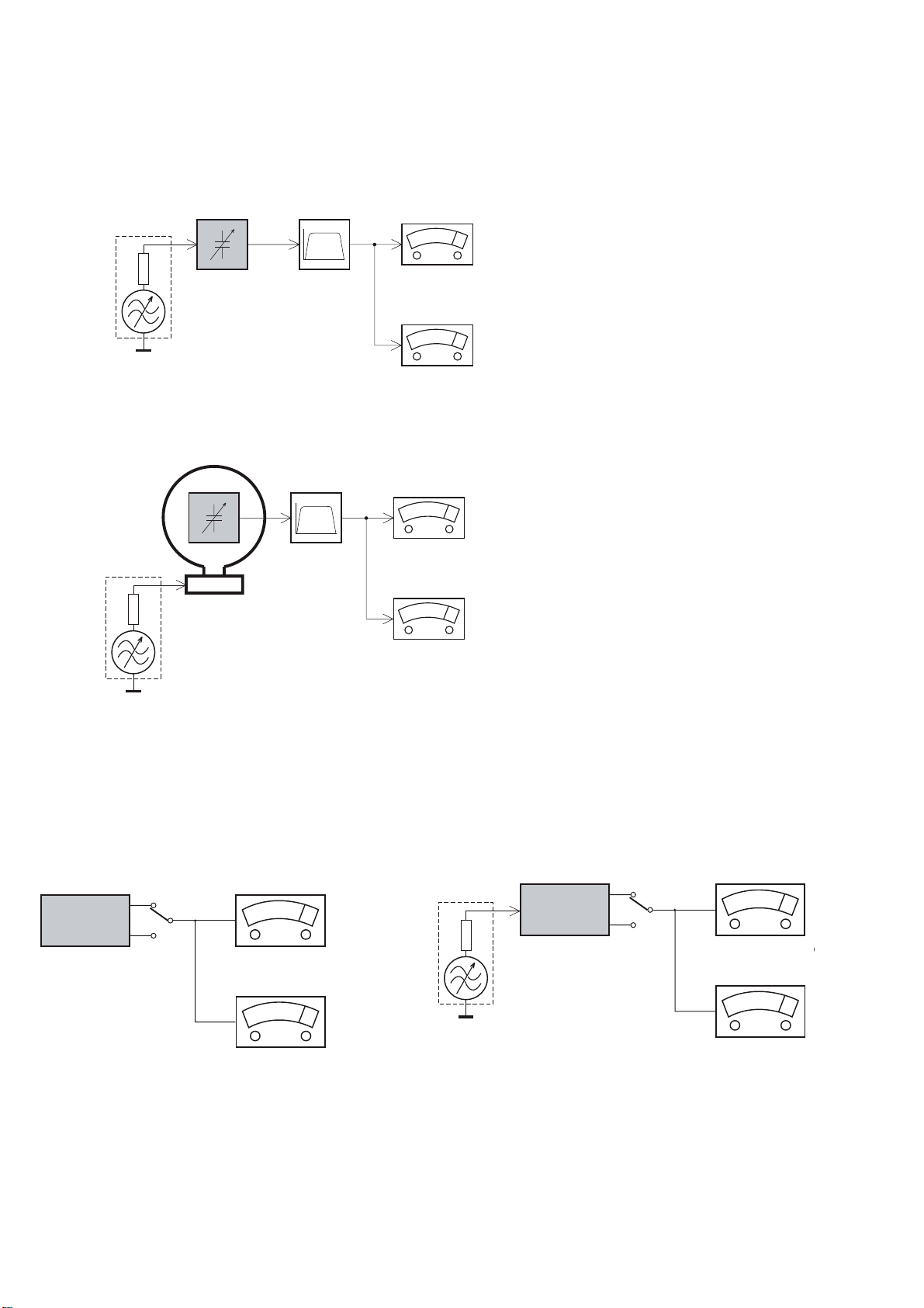
MEASUREMENT SETUP
Tuner FM
1-3
Bandpass
LF Voltmeter
e.g. PM2534
RF Generator
e.g. PM5326
DUT
250Hz-15kHz
e.g. 7122 707 48001
Ri=50:
S/N and distortion meter
e.g. Sound Technology ST1700B
Use a bandpass filter to eliminate hum (50Hz, 100Hz) and disturbance from the pilottone (19kHz, 38kHz).
Tuner AM (MW,LW)
RF Generator
e.g. PM5326
Ri=50:
DUT
Frame aerial
e.g. 7122 707 89001
Bandpass
250Hz-15kHz
e.g. 7122 707 48001
LF Voltmeter
e.g. PM2534
S/N and distortion meter
e.g. Sound Technology ST1700B
To avoid atmospheric interference all AM-measurements have to be carried out in a Faraday´s cage.
Use a bandpass filter (or at least a high pass filter with 250Hz) to eliminate hum (50Hz, 100Hz).
CD
Use Audio Signal Disc
(replaces test disc 3)
DUT
L
R
SBC429 4822 397 30184
S/N and distortion meter
e.g. Sound Technology ST1700B
LEVEL METER
e.g. Sennheiser UPM550
-
Recorder
Use Universal Test Cassette CrO2 SBC419 4822 397 30069
or Universal Test Cassette
LF Generator
e.g. PM5110
Fe SBC420 4822 397 30071
DUT
L
R
S/N and distortion met
e.g. Sound Technology ST170
LEVEL METER
e.g. Sennheiser UPM550
with FF-filter
Page 4
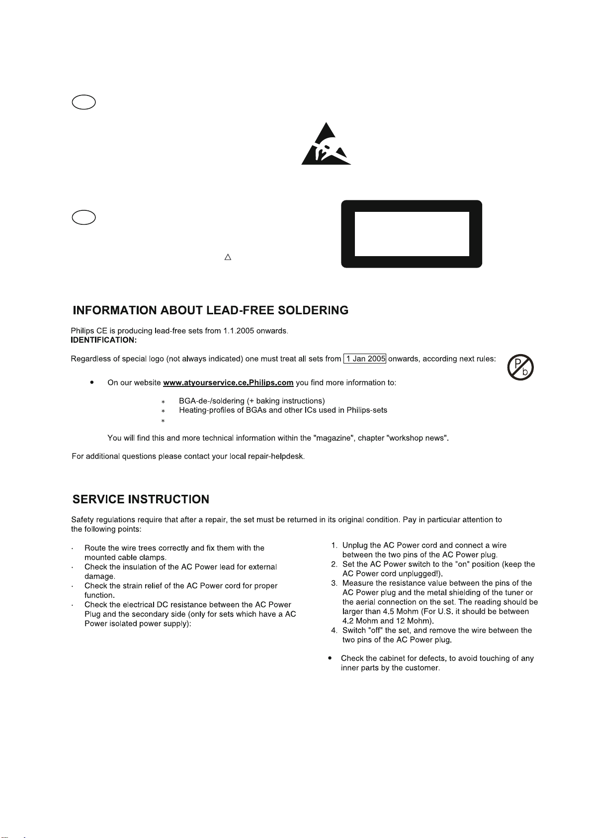
SERVICE AIDS
1-4
GB
All ICs and many other semi-conductors are
susceptible to electrostatic discharges (ESD).
Careless handling during repair can reduce life
drastically.
When repairing, make sure that you are
connected with the same potential as the mass
of the set via a wrist wrap with resistance.
Keep components and tools also at this
potential.
WARNING
GB
Safety regulations require that the set be restored to its original
condition and that parts which are identical with those specified,
be used
Safety components are marked by the symbol
!
.
ESD
CLASS 1
LASER PRODUCT
Lead free
Page 5
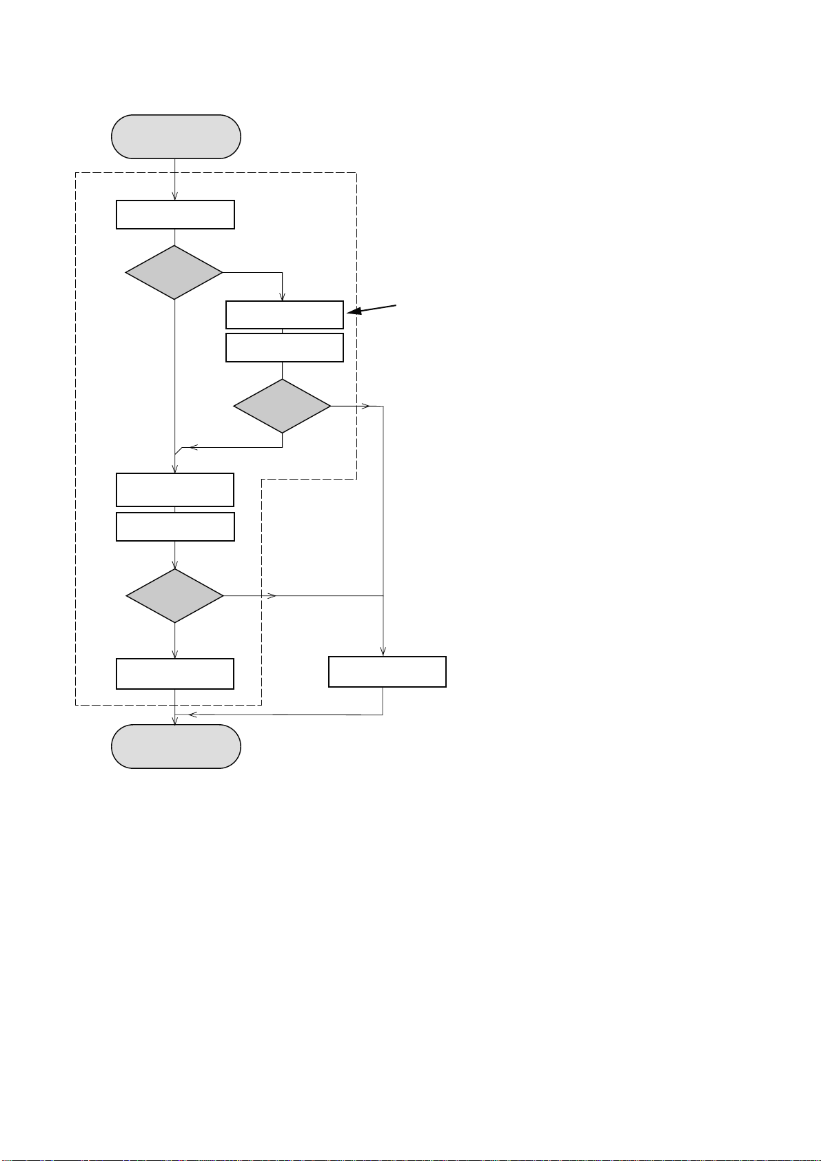
INSTRUCTIONS ON CD PLAYABILITY
Customer complaint
"CD related problem"
Set remains closed!
check playability
1
2 - 1
playability
ok ?
Y
Play a CD
for at least 10 minutes
check playability
playability
ok ?
Y
N
"fast" lens cleaning
check playability
playability
ok ?
N
3
N
Y
For flap loaders (= access to CD drive possible)
cleaning method
4 is recommended
add Info for customer
"SET OK"
2
return set
1 - 4 For description - see following pages
Exchange CDM
Page 6
INSTRUCTIONS ON CD PLAYABILITY
2 - 2
1
PLAYABILITY CHECK
For sets which are compatible with CD-RW discs
use CD-RW Printed Audio Disc....................7104 099 96611
TR 3 (Fingerprint)
TR 8 (600µ Black dot) maximum at 01:00
• playback of these two tracks without audible disturbance
playing time for: Fingerprint
Black dot from 00:50 to 01:10
• jump forward/backward (search) within a reasonable time
For all other sets
use CD-DA SBC 444A..................................4822 397 30245
TR 14 (600µ Black dot) maximum at 01:15
TR 19 (Fingerprint)
TR 10 (1000µ wedge)
• playback of all these tracks without audible disturbance
playing time for: 1000µ wedge 10seconds
Fingerprint 10seconds
Black dot from 01:05 to 01:25
• jump forward/backward (search) within a reasonable time
10seconds
4
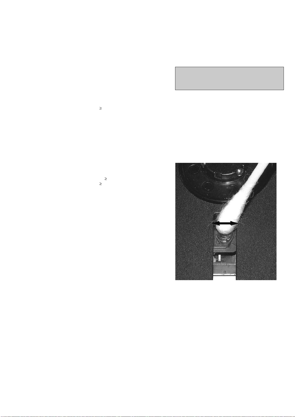
LIQUID LENS CLEANING
Before touching the lens it is advised to clean the
surface of the lens by blowing clean air over it.
This to avoid that little particles make scratches on
the lens.
Because the material of the lens is synthetic and coated
with a special anti-reflectivity layer, cleaning must be done
with a non-aggressive cleaning fluid. It is advised to use
“Cleaning Solvent
The actuator is a very precise mechanical component and
may not be damaged in order to guarantee its full function.
Clean the lens gently (don’t press too hard) with a soft and
clean cotton bud moistened with the special lens cleaner.
The direction of cleaning must be in the way as indicated in
the picture below.
2
CUSTOMER INFORMATION
It is proposed to add an addendum sheet to the set which
informs the customer that the set has been checked
carefully - but no fault was found.
The problem was obviously caused by a scratched, dirty or
copy-protected CD. In case problems remain, the customer
is requested to contact the workshop directly.
The lens cleaning (method 3) should be mentioned in the
addendum sheet.
The final wording in national language as well as the printing
is under responsibility of the Regional Service Organizations.
Page 7
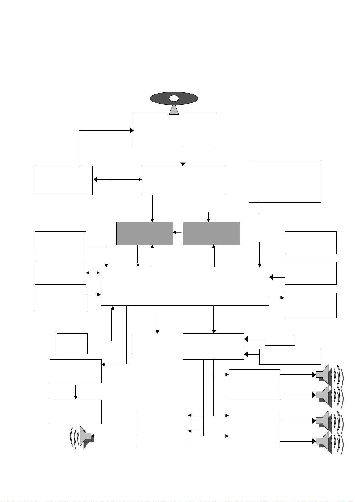
SET BLOCK DIAGRAM
E
R
R
3-1
3CDC CD Loader
PICK-UP MECHA
SANYO : DA-11VF
4 CH
MOTOR DRIVER
(BA5826)
RECORD TIME
(74LVC2G04)
SDRAM
16Mbit
NOR FLASH
SI636165
USB/SD
MMC
ROHM
RF AMP+SSP+DSP
(BU9543)
MUX
74VC157
ADC
WMA8781
MCS LOGIC BX8805
MP3/WMA En/De + MCU +USB/CARD
Port Expander
74HC4094
×
2
SOUND CONTROL
SW+VOL+EQ
(TDA7468 )
PLL Tuner
Si4730/4731
TIME/CLOCK(H
T1381)
Spectrum
analyzers
LED controller
for Light Box
(May use)
AUX
Karaoke(CD3699)
VFD DRIVER
T8862
DISPLAY
VFD
SUBWOFFER
amp
TDA8920
×
1
High power
AMP
TDA8920
Mid power amp
TDA8920
×
×
1
1
L
L
Page 8
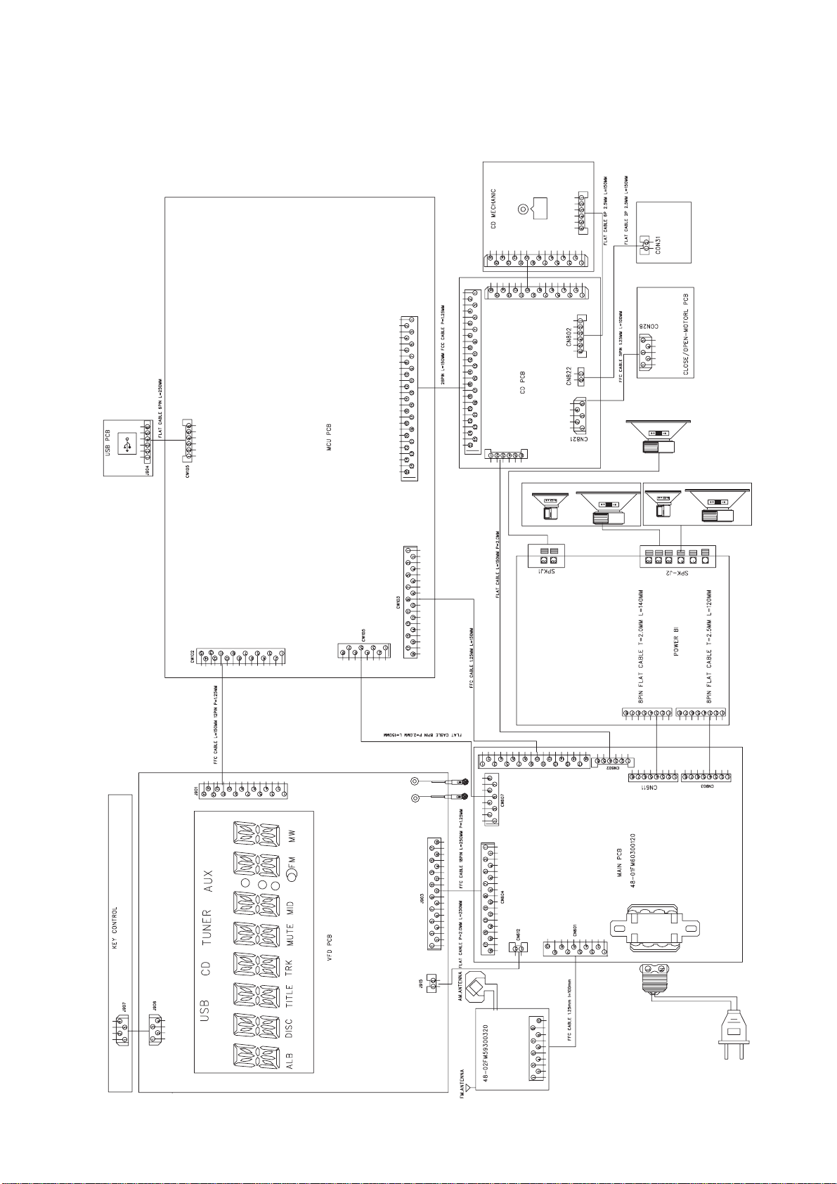
SET WIRING DIAGRAM
4-1
Page 9
5-1 5-1
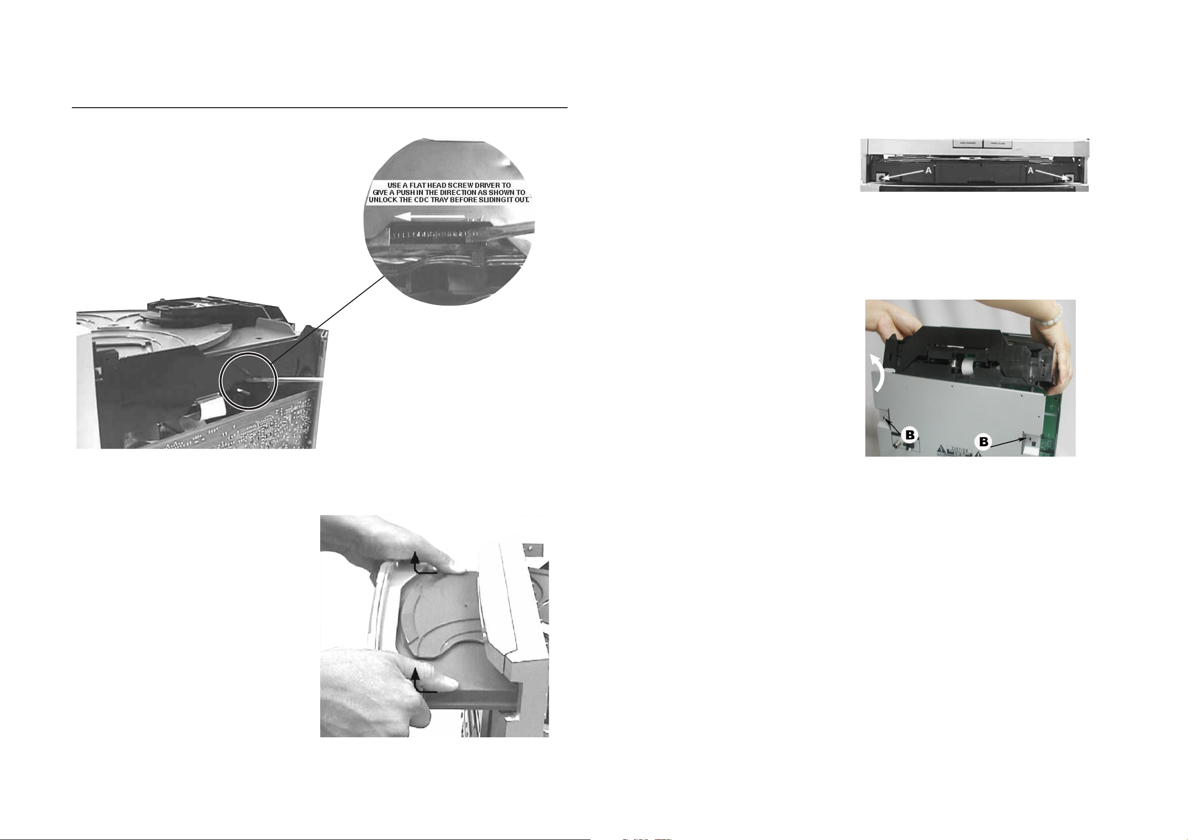
DISASSEMBLY DIAGRAM
Disman tling of the CDC Modu le and Front Panel
1) Loo sen 1 7 screw s to remo ve th e Cover T op of the s et.
2) Sli de ou t the CDC T ray as sh own i n the dia gram be low w ith
the he lp of a f lat hea d screw d riv er.
4) Loo sen 2 s crews A a nd 2 scre ws B to r emove t he CDC
Modu le as i ndica ted.
5) Rem ove 2 s crews a t the bot tom t o separ ate the
Fron t Pan el Asse mbly fr om th e plate b ottom .
Front View CDC
Sliding Out The CDC Tray
3) Rem ove t he Cove r Tray CD C as in dicat ed.
Remove CDC Module
Remove Cover Tray CDC
Page 10
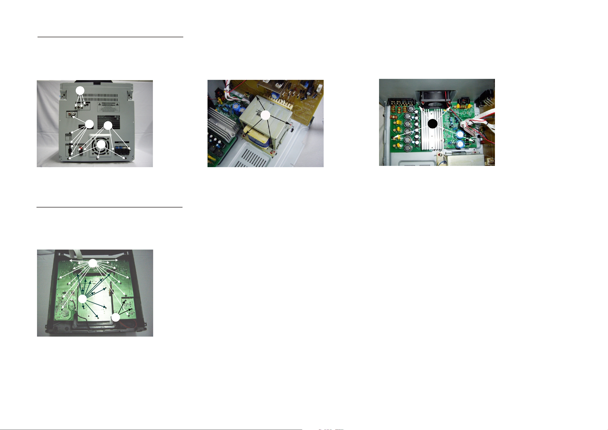
Disman tling of Rear Porti on
1)Re mov e 3 screw s C as indi cat ed to loo sen the Tun er Modu le.
2)Re mov e 9 screw s D&G as in dic ated to l oosen t he Ma in Boar d.
3)Re mov e 8 screw s E&H as in dic ated to l oosen t he AM P Board .
4)Re mov e 3 screw s F as indi cat ed to loo sen the B ott om Cabi net .
5-2 5-2
C
G
D
E
F
Disman tling of the PCB Boar d
1) Rem ove 1 4 screw s I as indi cat ed to loo sen the D isp lay Boa rd.
2) Rem ove 1 1 screw s J as indi cat ed to loo sen the K ey Bo ard.
3) Rem ove 2 s crews K a s indic ate d to loos en the US B jac k Board .
I
H
H
J
K
Page 11
CIRCUIT DIAGRAM - MAIN BOARD
PART1
6-1
6-1
Page 12

CIRCUIT DIAGRAM - MAIN BOARD
PART2
6-2
6-2
Page 13

LAYOUT DIAGRAM - MAIN BOARD
TOP SIDE
6-3
6-3
Page 14

LAYOUT DIAGRAM - MAIN BOARD
BOTTOM SIDE
6-4
6-4
Page 15

CIRCUIT DIAGRAM - CD BOARD
7-1
7-1
Page 16

LAYOUT DIAGRAM - CD BOARD
TOP SIDE
7-2
7-2
Page 17

LAYOUT DIAGRAM - CD BOARD
BOTTOM SIDE
7-3
7-3
Page 18

CIRCUIT DIAGRAM - MCU BOARD
8-1
8-1
Page 19

LAYOUT DIAGRAM - MCU BOARD
TOP SIDE
8-2
8-2
Page 20

LAYOUT DIAGRAM - MCU BOARD
BOTTOM SIDE
8-3
8-3
Page 21

CIRCUIT DIAGRAM - DISPLAY BOARD
9-1
9-1
Page 22

LAYOUT DIAGRAM - DISPLAY BOARD
TOP SIDE
9-2
9-2
Page 23

LAYOUT DIAGRAM - DISPLAY BOARD
BOTTOM SIDE
9-3
9-3
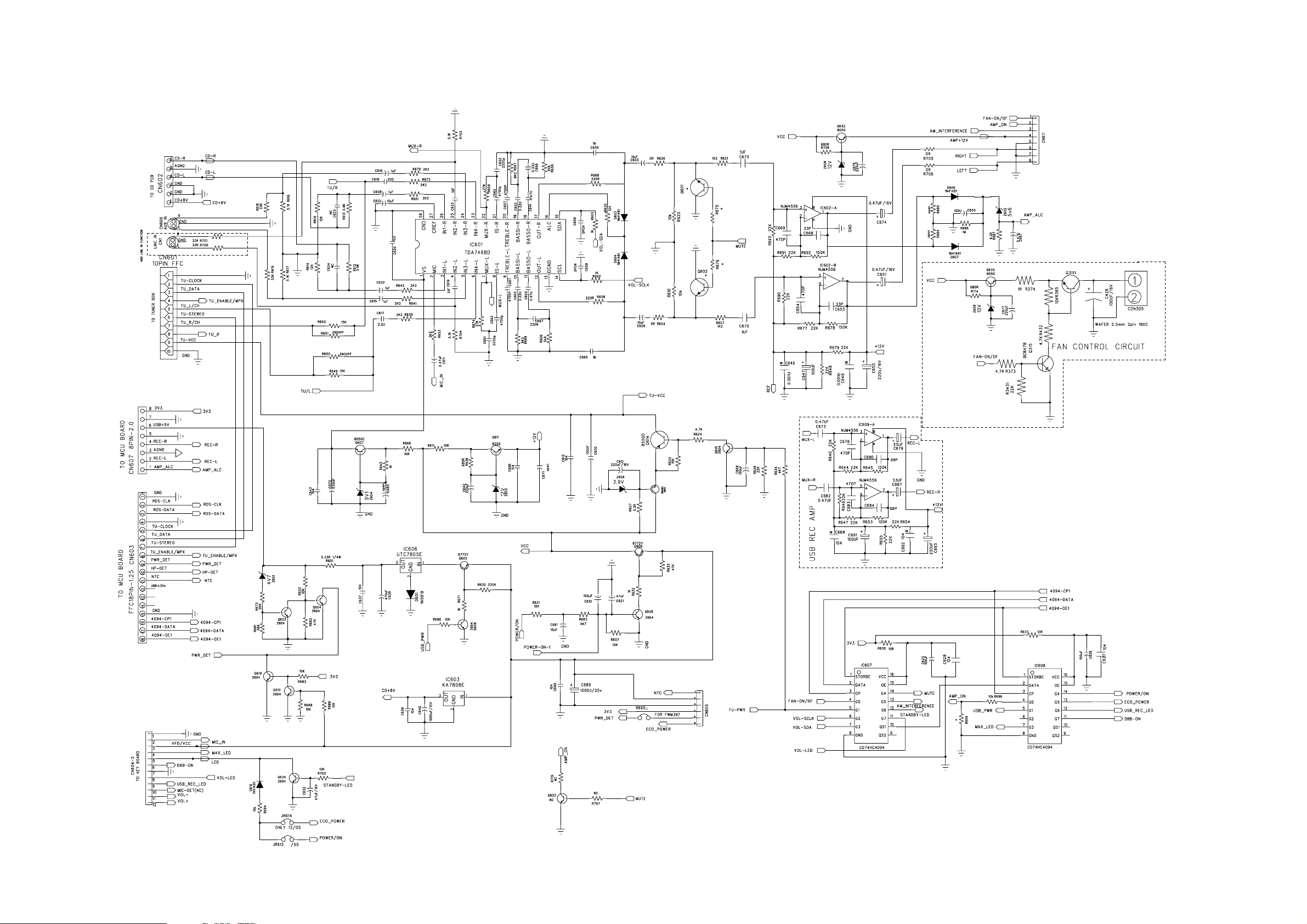
Page 24

CIRCUIT DIAGRAM - AMP BOARD
10-1
10-1
Page 25

LAYOUT DIAGRAM - AMP BOARD
TOP SIDE
10-2
10-2
Page 26

LAYOUT DIAGRAM - AMP BOARD
BOTTOM SIDE
10-3
10-3
Page 27

CIRCUIT DIAGRAM - TUNER BOARD
11-1
11- 1
Page 28

LAYOUT DIAGRAM - TUNER BOARD
11-2
11- 2
Page 29

EXPLODED VIEW DIAGRAM
12 - 1 12 - 1
Page 30

12 - 2
MECHANICAL PARTSLIST
082 994000003669 CD MECHANISM (SANYO) DA11VF
101 996510022972 FRONT CABINET
102 996510014310 MAGNET 27x16x4mm 546g
102 996510015489 ALBUM BUTTON
103 996510015490 TITLE BUTTON
104 996510015491 STOP BUTTON
105 996510015492 PLAY BUTTON
106 996510022984 USB REC BUTTON
107 996510022968 DISPLAY TOP BAR
110 996510014336 SPRING-GUIDING
111 996510014337 SPRING-DISC
201 994000001276 PANEL LEFT
202 994000001277 PANEL RIGHT
206 996510022977 3CDC DOOR
207 996510022978 COSMETIC COVER UP
208 996510022974 COSMETIC COVER DOWN
209 994000001285 TOP COVER
210 996510015502 CD BUTTON
215 996510014357 JAZZ-POP BUTTON
217 996510014361 ROCK-CLASSIS BUTTON
218 996510015493 MODE BUTTON
219 996510015494 PROGRAM BUTTON
220 996510015495 POWER BUTTON
221 996510015498 CLUSTER BUTTON
222 996510022973 VOL KNOB
223 996510022975 MAX SOUND BUTTON
225 996510020805 MIC KNOB
226 996510020806 USB DELETE BUTTON
227 996510014362 DISPLAY LENS (PMMA)
228 996510014363 POWER LIGHT GUIDE
229 996510000439 PHILIPS LOGO
231 996510014365 MIDDLE STRAP OF SOUND BUTTON
232 996510015500 MIDDLE STRAP L
233 996510015501 MIDDLE STRAP R
235 996510021305 USB RING
236 996510021316 VOL RING
004 996510025032 3CD MECHA PART DA11VF(NO PCBA)
8001 994000004487 16P FFC 1MM L=170MM
8003 994000004457 5P FFC L=200MM(AA)
J002 996510015477 26P FFC.1.25mm L=80mm
T001
J013 996500039522 4P FFC CABLE 1.25mm L=270mm
J014 996510016102 9P FFC.1.25mm L=80mm
J015 994000002431 FFC CABLE 10P L=120MM
J016 996510016103 14P FFC.1.25mm L=180mm
996510022981 TRANSFORMER EI86xS65 127/240V
!
J017 996510015486 18P FFC.1.25mm L=150mm
J018 996500040407 18P FFC 1.25mm L=130mm
Note: Only these parts mentioned in the list are
normal service parts.
Page 31

ACCESSORIES
S001 996510022982 SINGLE SPEAKER BOX L/R
S002 996510022971 SUBWOOFER BOX
0006 996510020798 REMOTE CONTROL
J010
!
996500037714 AC CORD SET VDE/BRAZIL APP 1.8
J011 996510009429 FM ANT (GREY) 1.5M CE/75
J012 996510002103 CONN. CORD 3.5 ST/PLUGx2 500mm
J013
!
994000001478 AC PLUG ADAPTOR
201 996510016101 AM LOOP ANTENNA
Note: Only these parts mentioned in the list are
normal service parts.
12 - 3
Page 32

ELECTRICAL PARTSLIST
MAIN BOARD ASSEMBL
Y
C910 996510022979 E.CAP 4700UF 25V +-20% 85C
C927 994000001225 SAFETY CAP 275V 0.22UF -20%
CN606 994000001221 V/RCA JACK 2P
F901
!
994000001223 FUSE RADIAL T5A 250V
F902
!
996510002426 CERAMIC FUSE 3.9x10.5mmW
F903
!
996510002426 CERAMIC FUSE 3.9x10.5mmW
F904
!
994000000586 GLASS FUSE W/LEAD 3.15A/250V
IC601 996510005250 IC TDA7468D
IC602 994000001201 IC NJM4556AM
IC603 996510018852 IC UTC7808
IC606 996510018962 IC UTC7805
IC607 994000001247 IC HEF4094BT
IC608 994000001247 IC HEF4094BT
IC609 994000001201 IC NJM4556AM
J001 996510014304 AC SOCKET UL APP
L900 994000001226 AC LINE FILTER IND. 400UH 3A
Q315 996510006580 SMD TRANSIST BC847C
Q605 994000004145 TRANSISTORS B772Y (160-320)
Q609 994000004145 TRANSISTORS B772Y (160-320)
SW901 994000001323 SWITCH
U901 996510016090 IC AP1117E33L-13
AMP BOARD ASSEMBL
Y
JSPK1 996510016371 SPK JACK
JSPK2 996510016097 SPK JACK 8P PT-24V11A
Q902 994000004545 TRANSISTORS BUK9507-30B
Q903 994000004545 TRANSISTORS BUK9507-30B
U301 996510003980 IC TDA8920(SOT566-3) 2X100W
U302 996510003980 IC TDA8920(SOT566-3) 2X100W
U304 996500042457 IC HEF4013BT
U305 996500042456 IC 74HCT04D SOP14
U306 996510003980 IC TDA8920(SOT566-3) 2X100W
U307 996500039808 IC SM LM324D
U308 994000001201 IC NJM4556AM
Y301 996500042460 CERAMIC RESONATOR 600KHz
Y302 996500042461 CERAMIC RESONATOR 700KHz
CD BOARD ASSEMBL
Y
IC501 996510009311 IC BU9543KV (SMD)
IC502 996510009310 IC BA5826FP
IC505 994000001247 IC HEF4094BT
SW501 994000004552 DETECT SWITCH
SW502 994000004552 DETECT SWITCH
SW503 994000004552 DETECT SWITCH
SW504 994000004552 DETECT SWITCH
U532 996510003998 IC TDA7073A/N4
13 - 1
Page 33

ELECTRICAL PARTSLIST
DISPLAY BOARD ASSEMBL
Y
CN905 996510000344 USB SOCKET
CN908 994000001244 V/PHONE JACK 3.5MM
CN909 994000001244 V/PHONE JACK 3.5MM
CN910 994000001244 V/PHONE JACK 3.5MM
D904 996510021295 LED LAMP 5mm
D914 996510000438 LED LAMP
IC901 996510020783 IC ET8862Q
IR901 994000000325 OPTIC SENSER (OPTO..)
LCD901 996510014305 LCD DISPLAY
SW901 994000001243 TACT SWITCH
SW902 994000001243 TACT SWITCH
SW903 994000001243 TACT SWITCH
SW904 994000001243 TACT SWITCH
SW905 994000001243 TACT SWITCH
SW906 994000001243 TACT SWITCH
SW907 994000001243 TACT SWITCH
SW908 994000001243 TACT SWITCH
SW909 994000001243 TACT SWITCH
SW910 994000001243 TACT SWITCH
SW911 994000001243 TACT SWITCH
SW912 994000001243 TACT SWITCH
SW913 994000001243 TACT SWITCH
SW914 994000001243 TACT SWITCH
SW915 994000001243 TACT SWITCH
SW916 994000001243 TACT SWITCH
SW917 994000001243 TACT SWITCH
SW918 994000001243 TACT SWITCH
SW919 994000001243 TACT SWITCH
SW920 994000001243 TACT SWITCH
SW921 994000001243 TACT SWITCH
SW922 994000001243 TACT SWITCH
SW923 994000001243 TACT SWITCH
SW925 994000001243 TACT SWITCH
SW926 994000001243 TACT SWITCH
SW927 994000001243 TACT SWITCH
SW928 994000001243 TACT SWITCH
SW929 994000001243 TACT SWITCH
SW930 994000001243 TACT SWITCH
VR1 996510003986 ROTARY VOLUME
VR902 996510003986 ROTARY VOLUME
VR903 996510021317 ROTARY ENCODER
13- 2
Page 34

ELECTRICAL PARTSLIST
MCU BOARD ASSEMBL
Y
IC101 996510015478 IC BX8800
IC102 996510009337 IC SST39VF800A-70 8M 3.3V TSOP
IC103 996510001318 IC 74LVC157APW
IC104 996510020772 IC SI636165TS
IC105 996510022969 IC HWD809R 2.63V
IC106 996510015480 IC WM8782SEDS
IC107 996510009335 IC LM1117S-1.8V SOT-223
IC108 996510015479 IC 74LVC2G04GW
IC191 996510015481 IC HT1381
X101 996510008326 CRYSTAL 12 MHzHC-49/US H=3.5mm
X102 996510015482 CRYSTAL 11.2896MHz
X191 996510012559 CRYSTAL 32.768KHZ
TUNER BOARD ASSEMBL
Y
IC301 996510022983 IC SI4730
JCN302 994000001353 COAXIAL JACK IF-01A
T301 996510000886 AM ANT BLACK 7mm 7M4A1951X
X301 996500042441 X'TAL 32.768KHZ -20PPM
Note: Onl
y
theseparts mentioned in the list are
y p
normal service parts.
13 - 3
 Loading...