

Philips FWM-377 Service manual
Mini System
FWM377/05/12/55
TABLE OF CONTENTS
Specifi cations ..............................................................1-1
Location of PCBs.........................................................1-2
Specification ................................................................1-3
Measurement Setup ....................................................1-4
Service Aids, Safety Instruction, etc ..................1-5 to 1-7
Block Diagram ................................................................2
Wiring Diagram ...............................................................3
Front Board & USB Board ..............................................4
CPU/WMA Board ............................................................5
Main Board & Power Board ............................................ 6
AMP (Low Power) Board ................................................ 7
Mechanical Exploded View & Parts List .........................8
Revision List ...................................................................9
©
Copyright 2007 Philips Consumer Electronics B.V. Eindhoven, The Netherlands
All rights reserved. No part of this publication may be reproduced, stored in a retrieval system or
transmitted, in any form or by any means, electronic, mechanical, photocopying, or otherwise without
the prior permission of Philips.
Published by SL0750 Service Audio Printed in The Netherlands Subject to modifi cation.
Page
CLASS 1
LASER PRODUCT
GB
3141 785 31631
Version 1.1
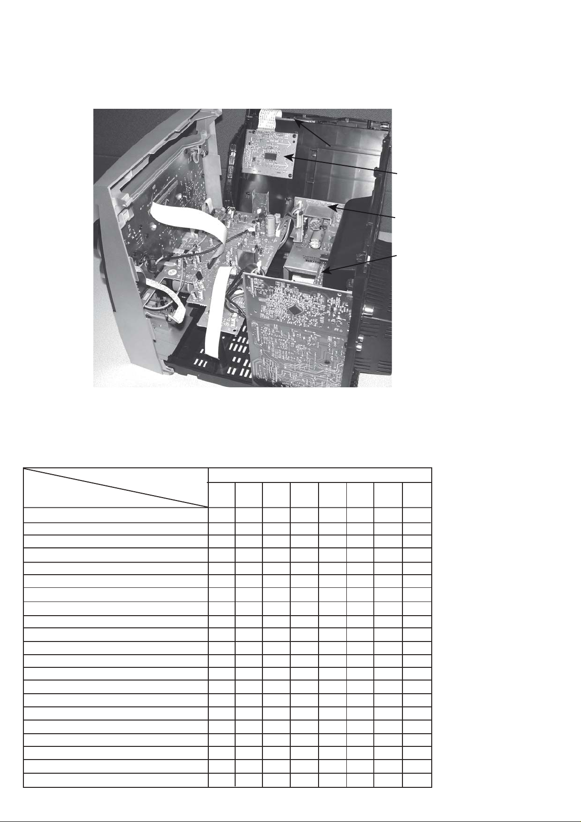
LOCATION OF PCBS
1-2
CD BOARD
CPU BOARD
KEY BOARD
MAIN BOARD
VERSION VARIATIONS:
Type /Versions: FWM377
Features &
Board in used:
CPU/WMA Board /55
CPU/WMA Board /12
Voltage Selector
Digital Output
Line Output
Matrix Surround Loudspeakers
ECO Standby - Dark
ECO6 Tuner board - System Non-Cenelec
ECO6 Tuner board - System Cenelec
ETF7 Tape Module: Non-Autoreverse Ferro x x x
USB Direct
/05 /12 /55
x
x
xxx
x
x
x
x
x
xxx
POWER BOARD
HF POWER BOARD
AMP BOARD
x
x
xxxtupnI xuA
xxxtekcoS enohpdaeH
xxyalpsiD kcolC DTF - ybdnatS
x

SPECIFICATION
1-3
AMPLIFIER
RMS output power
1KHz (Low channel-both channels driven) .......
............................................................. 60 W per channel
10KHz (High channel-both channels driven) ....
............................................................. 60 W per channel
Total output power ........................................... 240 W
Signal-to-noise ratio .......................... 67 dB A (IEC)
Frequency response .......................... 50 – 16000 Hz
Input sensitivity
AUX ................................................. 1500mV/2000mV
Output
Speakers .................................................................... 6 :
Headphones ............................................................. 32 :
(1) (8 :, 1 kHz, 10% THD)
CD/MP3-CD PLAYER
Number of programmable tracks ......................... 40
Frequency response ............. 50 – 20000 Hz -3dB
Signal-to-noise ratio ....................................... 75 dB A
Channel separation .......................... 50 dB (1 kHz)
Total harmonic distor tion ................................. < 1.5%
MPEG 1 Layer 3 (MP3-CD) .......... MPEG AUDIO
MP3-CD bit rate ....................................... 32-256 kbps
(128 kbps advised)
Sampling frequencies ....................... 32, 44.1, 48 kHz
TAPE PLAYER
Frequency response
Normal tape (type I) ...... 125 – 8000 Hz (8 dB)
Signal-to-noise ratio
Normal tape (type I) ................................. 48 dB A
Wow and flutter ......................................... d 0.4% DIN
SPEAKERS
System 2-way; double port bass reflex
Impedance ........................................................................ 6 :
Woofer .................................................................. 1 x 13cm
Tweeter..................................................................... 1 x 5cm
Dimensions (w x h x d) ....27.3 x 31 x 20.4 (cm)
Weight ............................................................. 3.65 kg each
GENERAL
Material/finish ................................... Polystyrene/Metal
AC Power ..................................... 220 – 230 V / 50 Hz
Power Consumption
Active ...................................................................... 120 W
Standby .................................................................. d 15 W
Eco Power standby ........................................ d 1 W
Dimensions (w x h x d) ..... 26.5 x 31 x 38.4 (cm)
Weight (without speakers) ................................. 9.1 kg
TUNER
FM wave range ................................... 87.5 – 108 MHz
MW wave range ................................ 531 – 1602 kHz
Number of presets ........................................................ 40
Antenna
FM ....................................................................... 75 : wire
MW ............................................................ Loop antenna
USB PLAYER
USB ................................................................... 12Mb/s, V1.1
......................................... support MP3 and WMA files
Number of albums/folders ................. maximum 99
Number of tracks/titles ...................... maximum 400
Specifications and external appearance are
subject to change without notice.
e
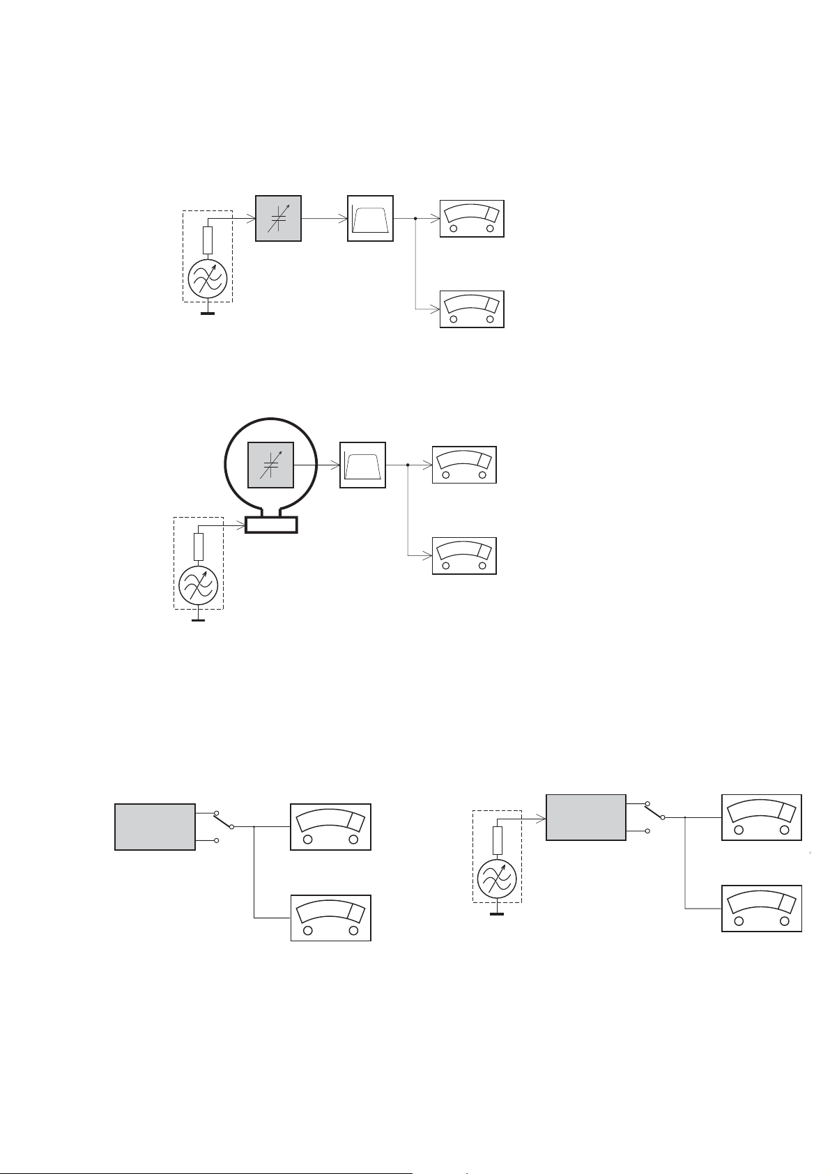
MEASUREMENT SETUP
Tuner FM
1-4
Bandpass
LF Voltmeter
e.g. PM2534
RF Generator
e.g. PM5326
DUT
250Hz-15kHz
e.g. 7122 707 48001
Ri=50Ω
S/N and distortion meter
e.g. Sound Technology ST1700B
Use a bandpass filter to eliminate hum (50Hz, 100Hz) and disturbance from the pilottone (19kHz, 38kHz).
Tuner AM (MW,LW)
RF Generator
e.g. PM5326
Ri=50Ω
DUT
Frame aerial
e.g. 7122 707 89001
Bandpass
250Hz-15kHz
e.g. 7122 707 48001
LF Voltmeter
e.g. PM2534
S/N and distortion meter
e.g. Sound Technology ST1700B
To avoid atmospheric interference all AM-measurements have to be carried out in a Faraday´s cage.
Use a bandpass filter (or at least a high pass filter with 250Hz) to eliminate hum (50Hz, 100Hz).
CD
Use Audio Signal Disc
(replaces test disc 3)
DUT
L
R
SBC429 4822 397 30184
S/N and distortion meter
e.g. Sound Technology ST1700B
LEVEL METER
e.g. Sennheiser UPM550
-
Recorder
Use Universal Test Cassette CrO2 SBC419 4822 397 30069
or Universal Test Cassette
LF Generator
e.g. PM5110
Fe SBC420 4822 397 30071
DUT
L
R
S/N and distortion met
e.g. Sound Technology ST170
LEVEL METER
e.g. Sennheiser UPM550
with FF-filter
SERVICE AIDS
1-5
Service Tools:
Universal Torx driver holder .................................4822 395 91019
Torx bit T10 150mm ...........................................4822 395 50456
Torx driver set T6-T20 .........................................4822 395 50145
Torx driver T10 extended .....................................4822 395 50423
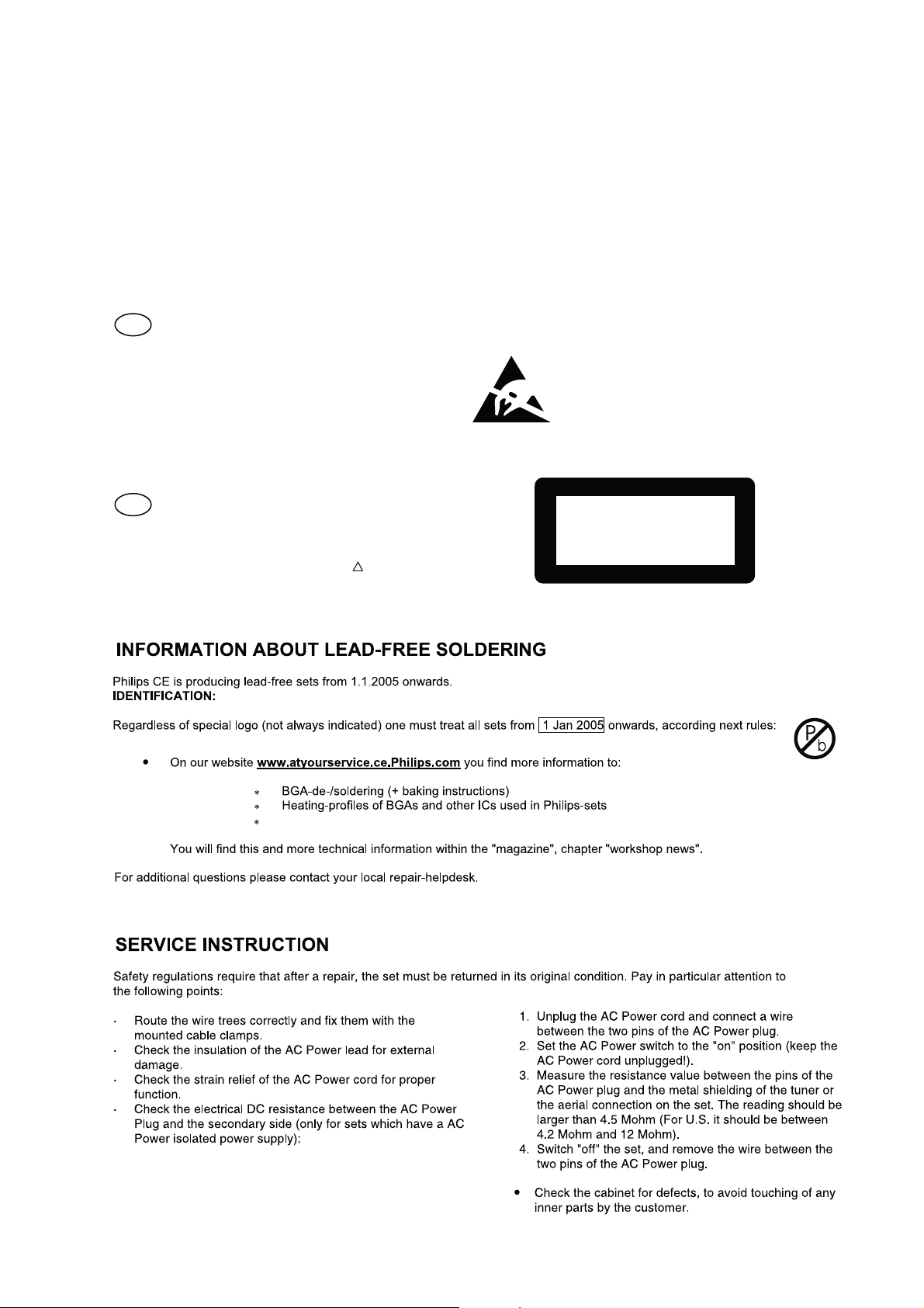
GB
All ICs and many other semi-conductors are
susceptible to electrostatic discharges (ESD).
Careless handling during repair can reduce life
drastically.
When repairing, make sure that you are
connected with the same potential as the mass
of the set via a wrist wrap with resistance.
Keep components and tools also at this
potential.
WARNING
GB
Safety regulations require that the set be restored to its original
condition and that parts which are identical with those specified,
be used
Safety components are marked by the symbol
!
.
Compact Disc:
SBC426/426A Test disc 5 + 5A ...........................4822 397 30096
SBC442 Audio Burn-in test disc 1kHz .................4822 397 30155
SBC429 Audio Signals disc .................................4822 397 30184
Dolby Pro-logic Test Disc ....................................4822 395 10216
ESD
CLASS 1
LASER PRODUCT
Lead free
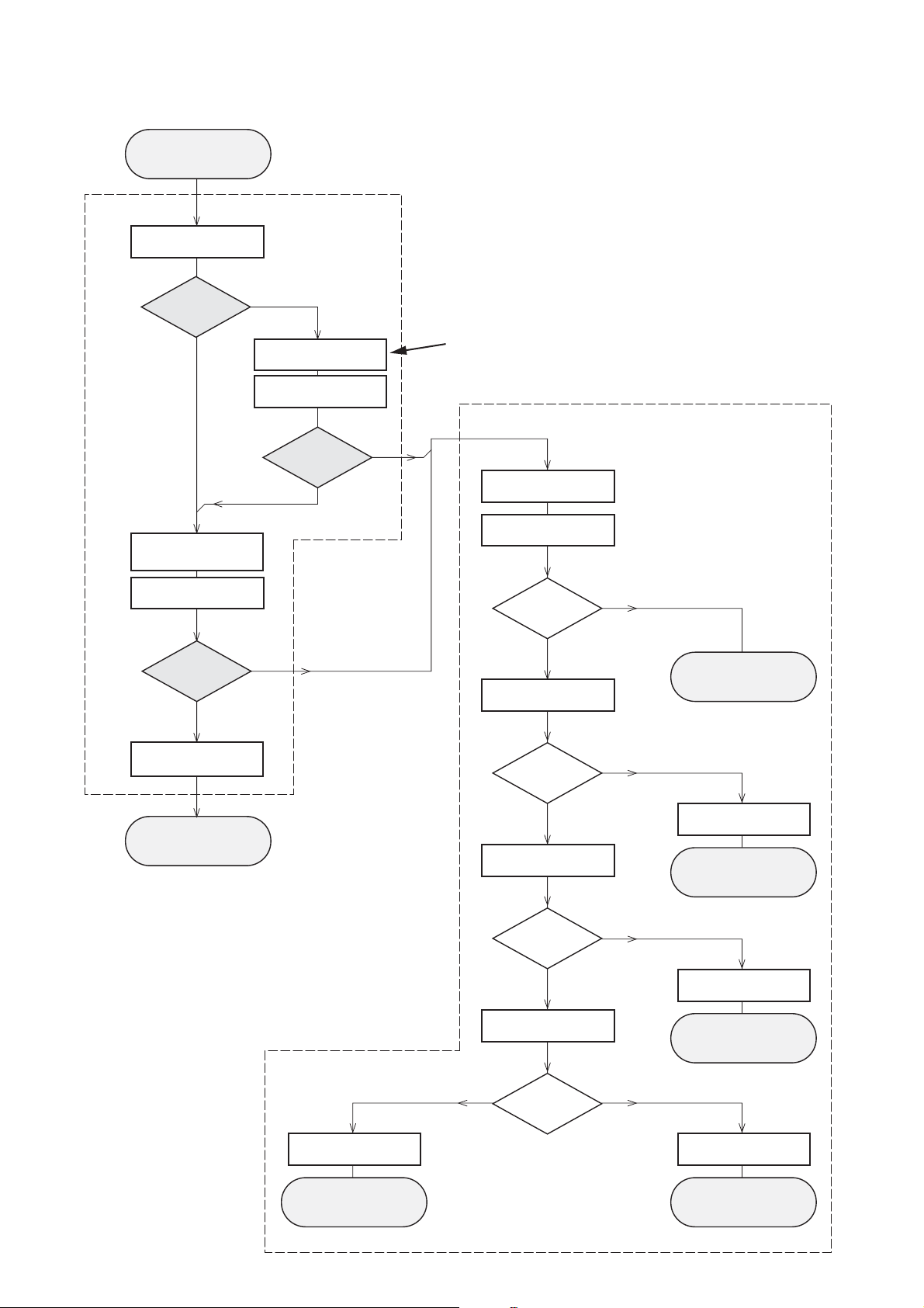
INSTRUCTIONS ON CD PLAYABILITY
Customer complaint
"CD related problem"
Set remains closed!
check playability
1
1-6
playability
ok ?
Y
Play a CD
for at least 10 minutes
check playability
playability
ok ?
Y
N
"fast" lens cleaning
check playability
playability
ok ?
N
3
For flap loaders (= access to CD drive possible)
cleaning method
4 is recommended
Standard repair procedure
N
Y
clean the lens
check playability
playability
ok ?
check "EYE-Pattern"
4
Y
N
5
return set
add Info for customer
"SET OK"
return set
1 - 7
For description - see following pages
2
replace Signal Processor
return set
EYE-Pattern
ok ?
Y
check Laser current
Laser current
ok ?
Y
check CD Drive offsets
Y
CD Drive offsets
ok ?
N
replace CD Drive
6
return set
N
replace CD Drive
7
return set
N
replace CD Drive
return set
INSTRUCTIONS ON CD PLAYABILITY
1-7
1
PLAYABILITY CHECK
For sets which are compatible with CD-RW discs
use CD-RW Printed Audio Disc....................7104 099 96611
TR 3 (Fingerprint)
TR 8 (600µ Black dot) maximum at 01:00
• playback of these two tracks without audible disturbance
playing time for: Fingerprint ≥10seconds
Black dot from 00:50 to 01:10
• jump forward/backward (search) within a reasonable time
For all other sets
use CD-DA SBC 444A..................................4822 397 30245
TR 14 (600µ Black dot) maximum at 01:15
TR 19 (Fingerprint)
TR 10 (1000µ wedge)
• playback of all these tracks without audible disturbance
playing time for: 1000µ wedge ≥10seconds
Fingerprint ≥10seconds
Black dot from 01:05 to 01:25
• jump forward/backward (search) within a reasonable time
4
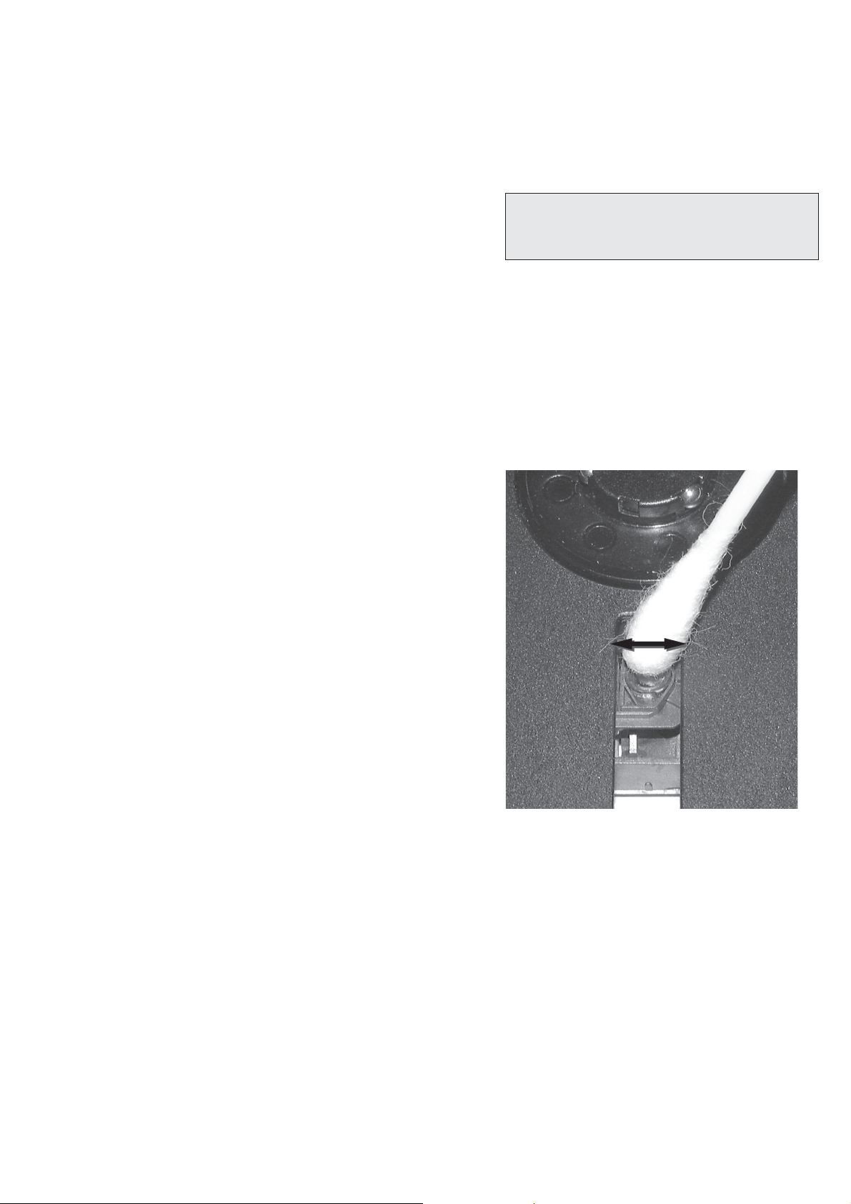
LIQUID LENS CLEANING
Before touching the lens it is advised to clean the
surface of the lens by blowing clean air over it.
This to avoid that little particles make scratches on
the lens.
Because the material of the lens is synthetic and coated
with a special anti-reflectivity layer, cleaning must be done
with a non-aggressive cleaning fluid. It is advised to use
“Cleaning Solvent B4-No2”, available with codenumber
4822 389 10026.
The actuator is a very precise mechanical component and
may not be damaged in order to guarantee its full function.
Clean the lens gently (don’t press too hard) with a soft and
clean cotton bud moistened with the special lens cleaner.
The direction of cleaning must be in the way as indicated in
the picture below.
2
CUSTOMER INFORMATION
It is proposed to add an addendum sheet to the set which
informs the customer that the set has been checked
carefully - but no fault was found.
The problem was obviously caused by a scratched, dirty or
copy-protected CD. In case problems remain, the customer
is requested to contact the workshop directly.
The lens cleaning (method 3) should be mentioned in the
addendum sheet.
The final wording in national language as well as the printing
is under responsibility of the Regional Service Organizations.
3
FAST LENS CLEANING (dry brush)
Use lens cleaning CD
SBC AC300...........................................9082 100 00043
Insert the lens cleaning CD, press PLAY and follow the
voice guide´s instructions on the CD.
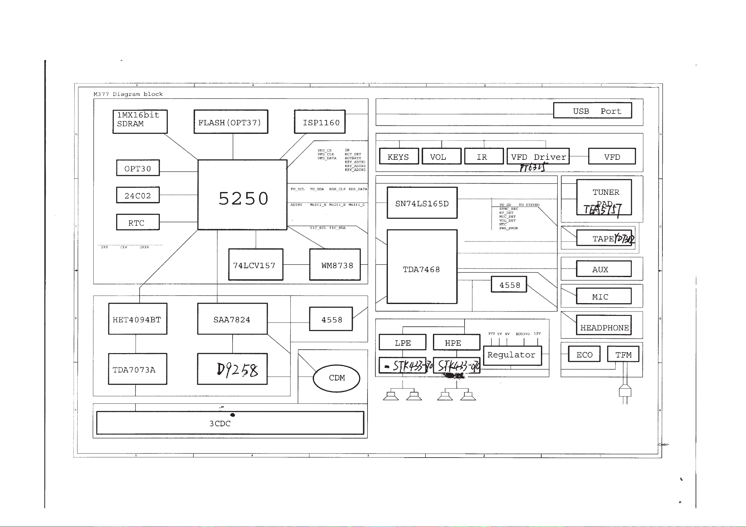
SET BLOCK DIAGRAM
2-1
2-1
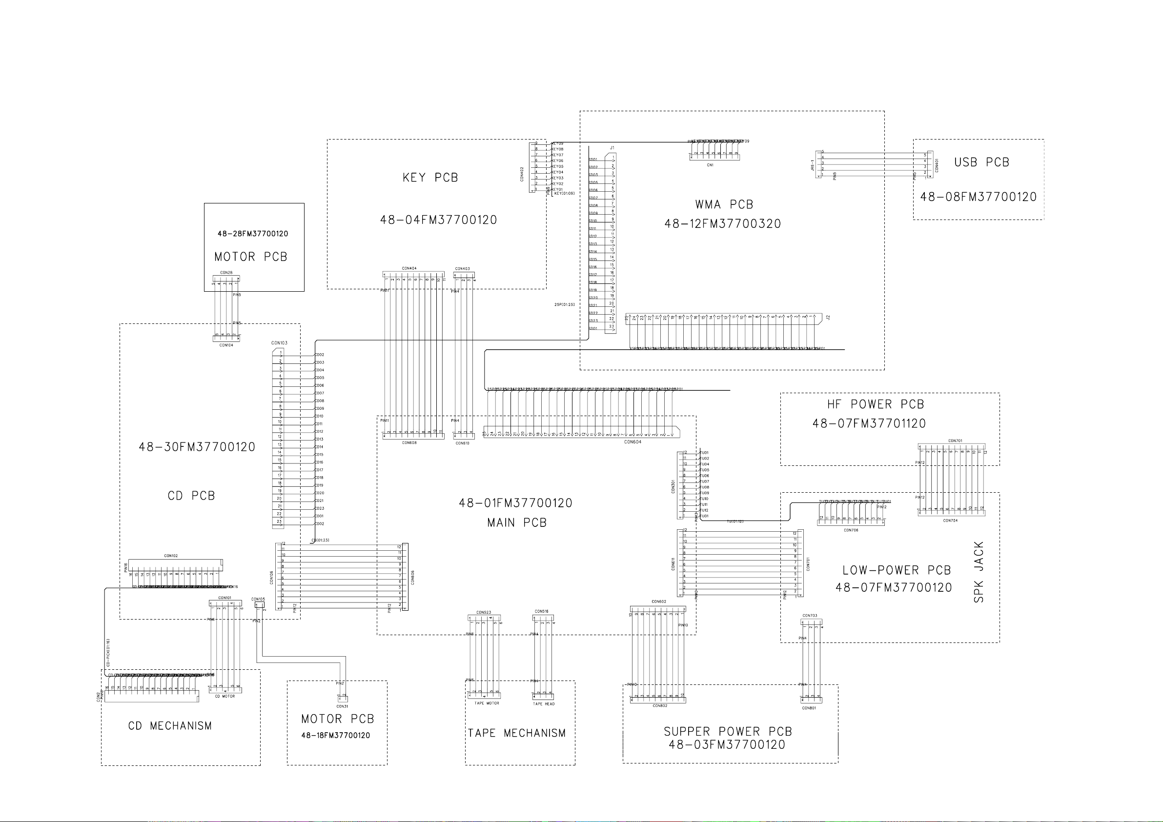
SET WIRING DIAGRAM
3-1
3-1

4-1 4-1
FRONT & USB BOARD
TABLE OF CONTENTS
Front PCB - Layout Top View .......................................... 6-2
Front PCB - Layout Bottom View .....................................6-3
Front & USB PCB - Circuit Diagram .................................6-4
USB PCB - Layout ........................................................... 6-5
4-2 4-2
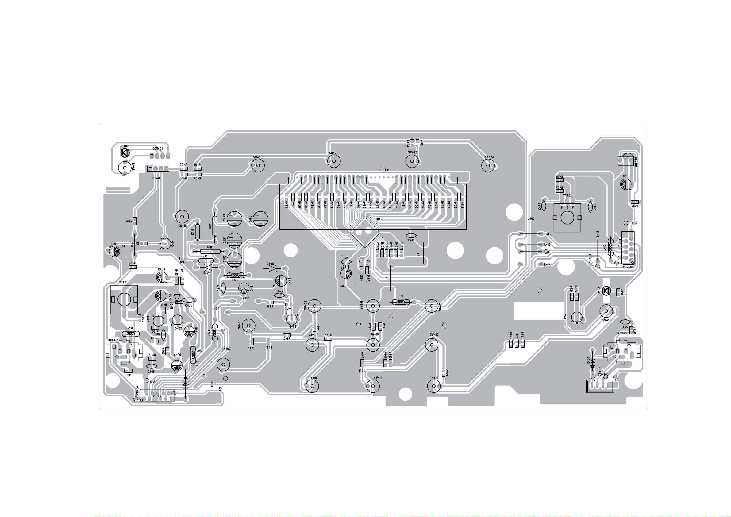
PCB LAYOUT - FRONT BOARD (TOP VIEW)
4-3
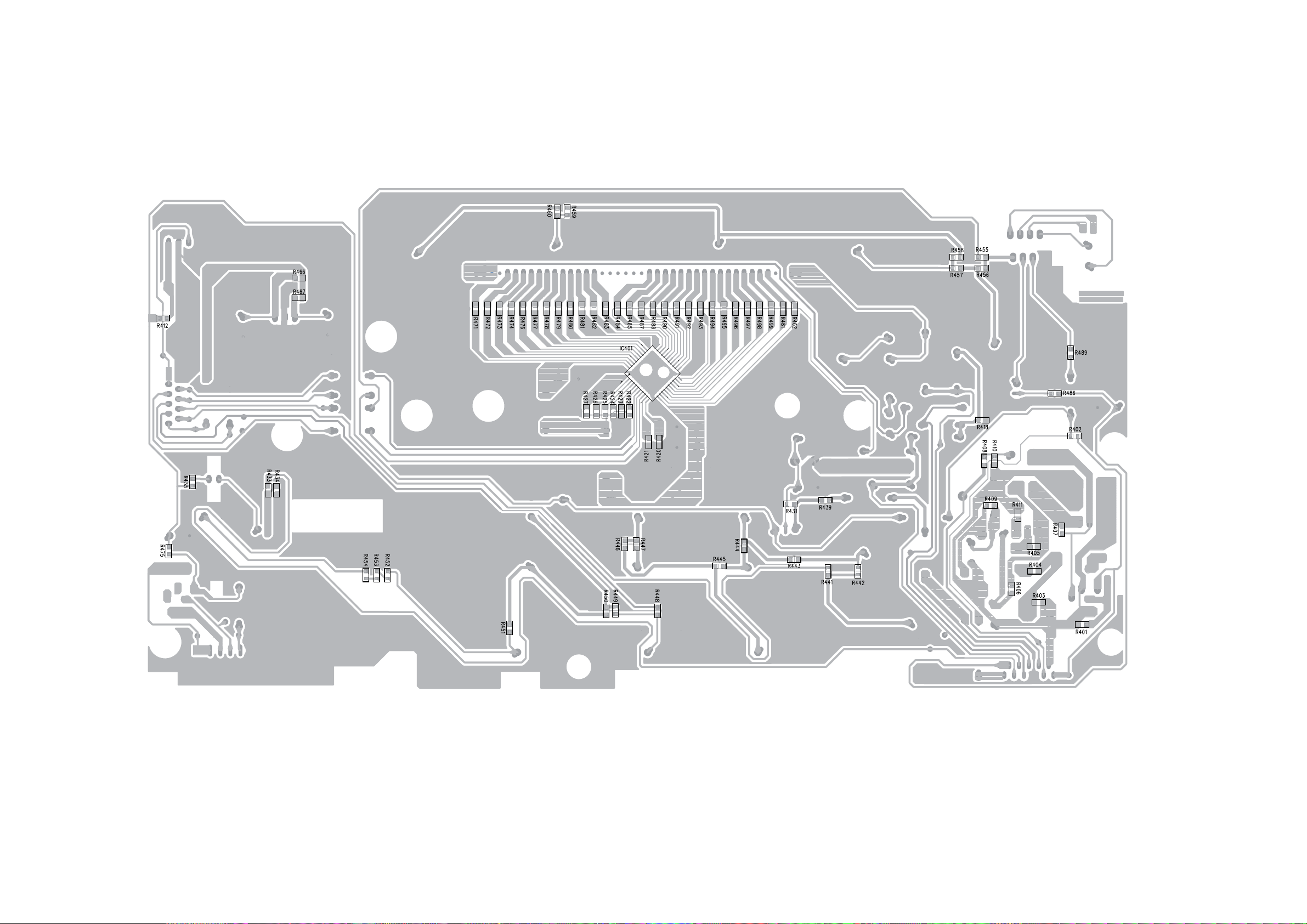
PCB LAYOUT - FRONT BOARD (BOTTOM VIEW)
4-3
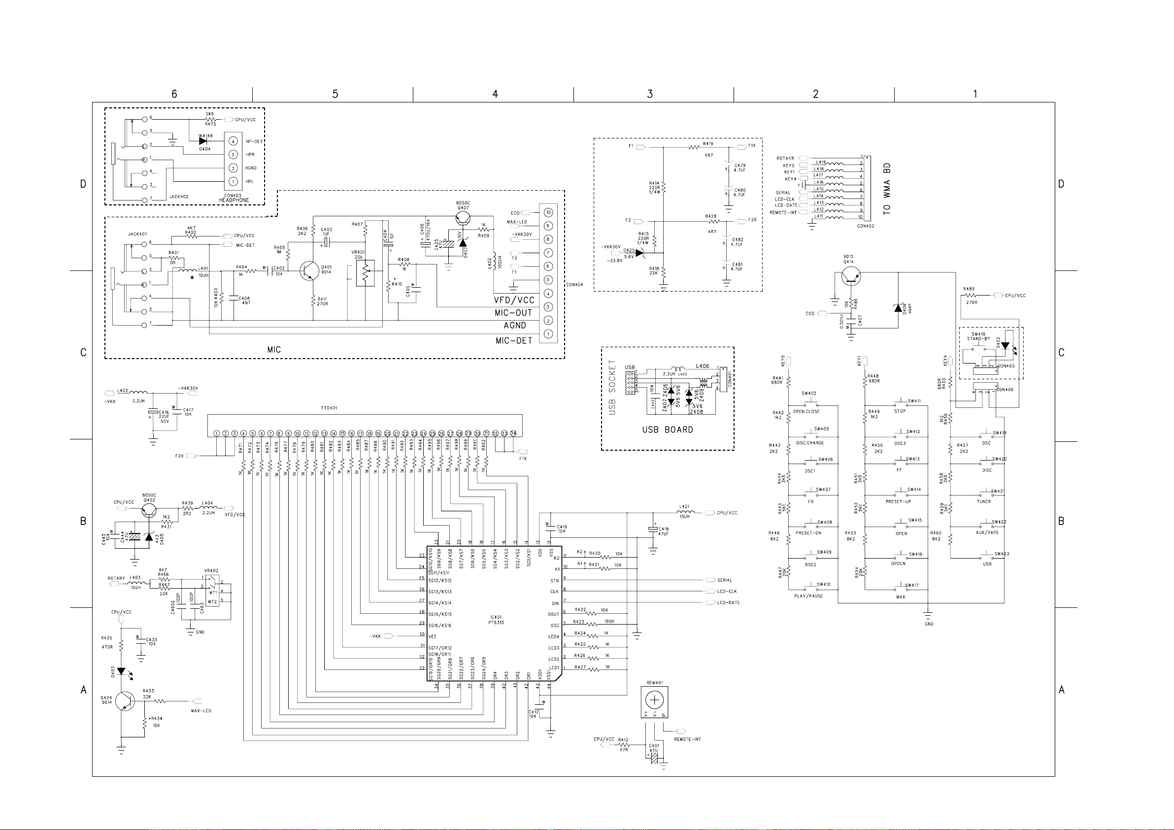
CIRCUIT DIAGRAM - FRONT BOARD
4-4
4-4
 Loading...