

Philips FWD-832 Service Manual
Version 1.0
FWD832
© 3141 785 31170
DVD Mini System
all versions
Published by LX 0644 Service Audio Subject to modification
©
Copyright 2006 Philips Consumer Electronics B.V. Eindhoven, The Netherlands
All rights reserved. No part of this publication may be reproduced, stored in a retrieval
system or transmitted, in any form or by any means, electronic, mechanical, photocopying,
or otherwise without the prior permission of Philips.
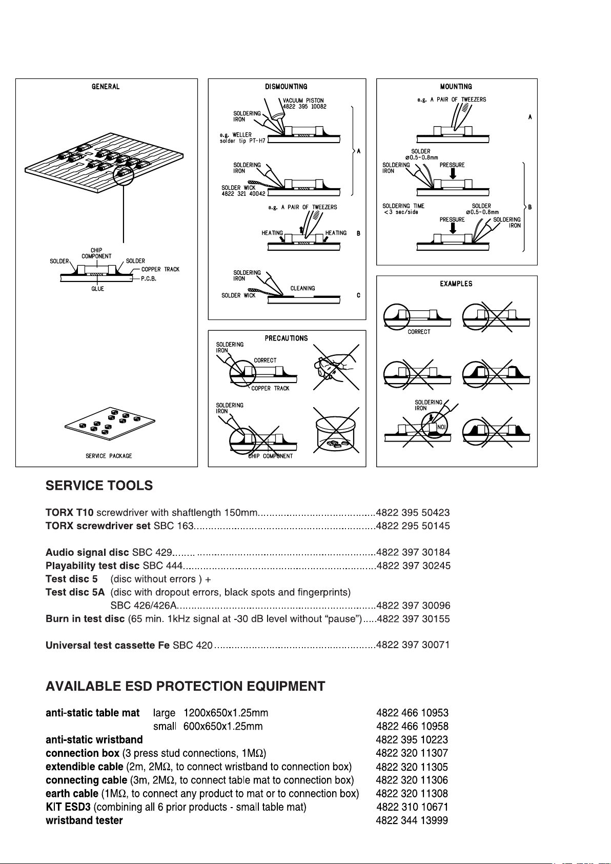
Handling chip components ........................................................... 1-1
Service tools ................................................................................. 1-1
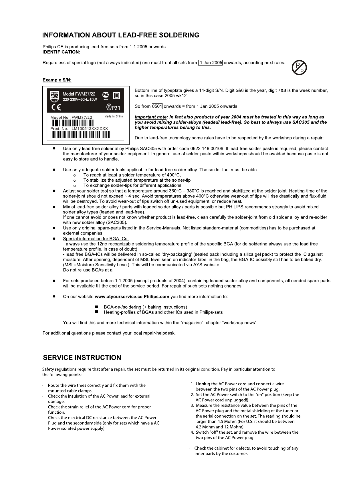
Leadfree and safety information ................................................... 1-2
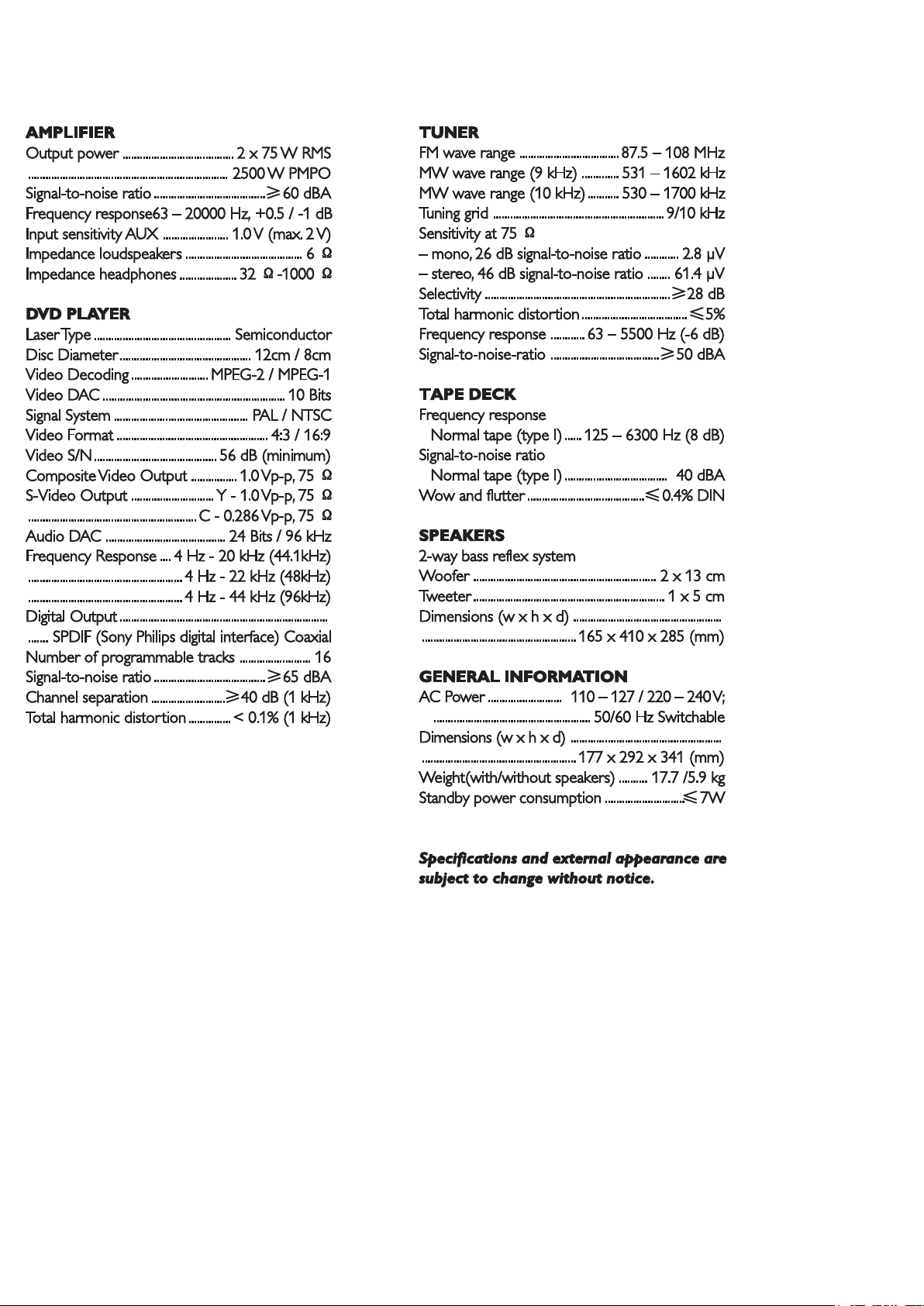
Technical specification .................................................................. 2-1
Service measurement setup ......................................................... 2-2
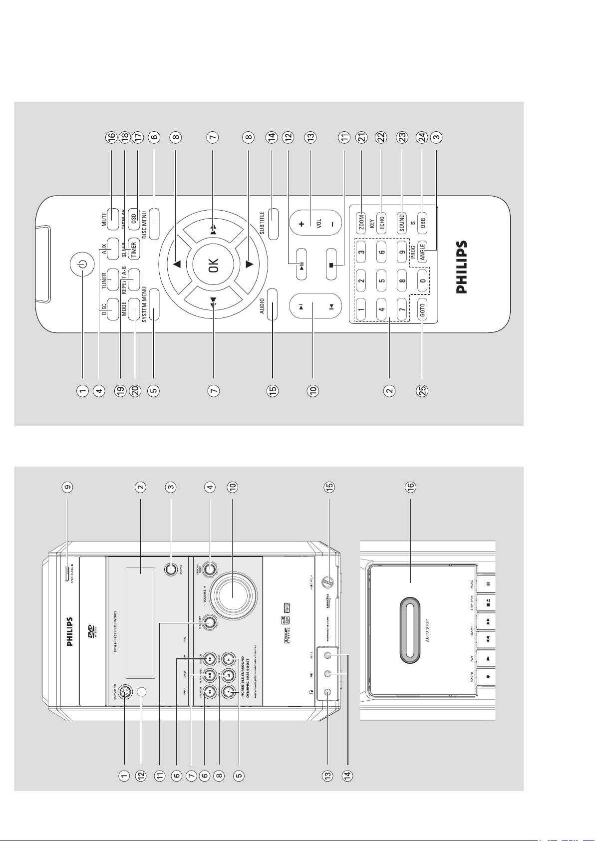
Connections and controls...................................................... 3-1...3-2
Software version and upgrading ................................................... 4-1
Block diagram................................................................................ 5-1
Wiring diagram ............................................................................. 6-1
Display board
circuit diagram ................................................................. 7-1...7-2
layout diagram layout diagram layout diagram ................................................................. 7-3...7-4
Main board
circuit diagram. ................................................................. 8-1...8-2
layout diagram .................................................................. 8-3...8-4
DVD MPEG board
circuit diagram. ......................................................................... 9-1
layout diagram .......................................................................... 9-2
DC Power Board
circuit diagram. ....................................................................... 10-1
layout diagram ........................................................................ 10-1
Exploded view diagram ................................................................11-1
Mechanical partslist ......................................................................11-2
Electrical partslist ..............................................................12-1...12-4
TABLE OF CONTENTS
1 - 1
HANDLING CHIP COMPONENTS
1 - 2
2 - 1
SPECIFICATION
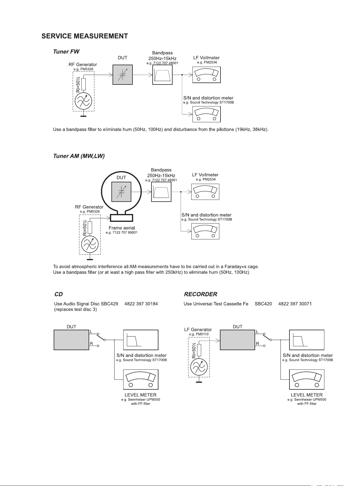
2 - 2
3 - 1
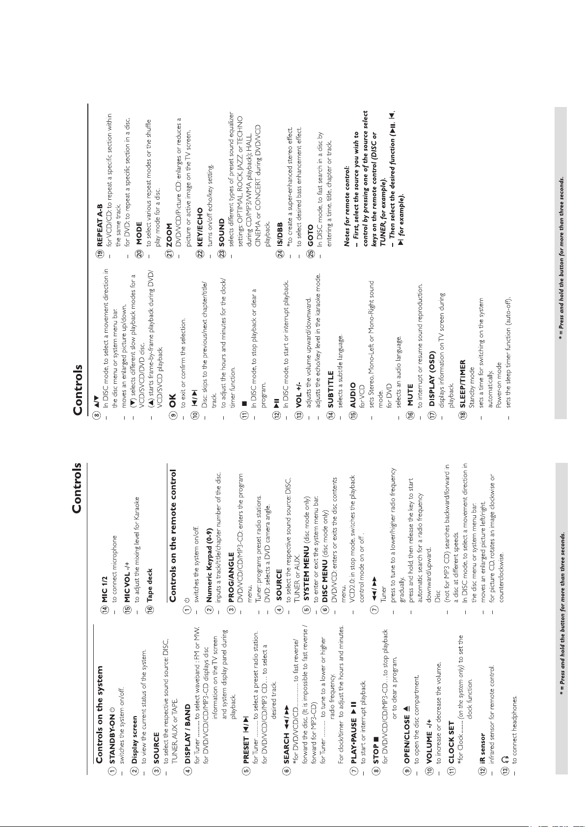
CONNECTION AND CONTROLS
3 - 2
CONNECTION AND CONTROLS
N
Y
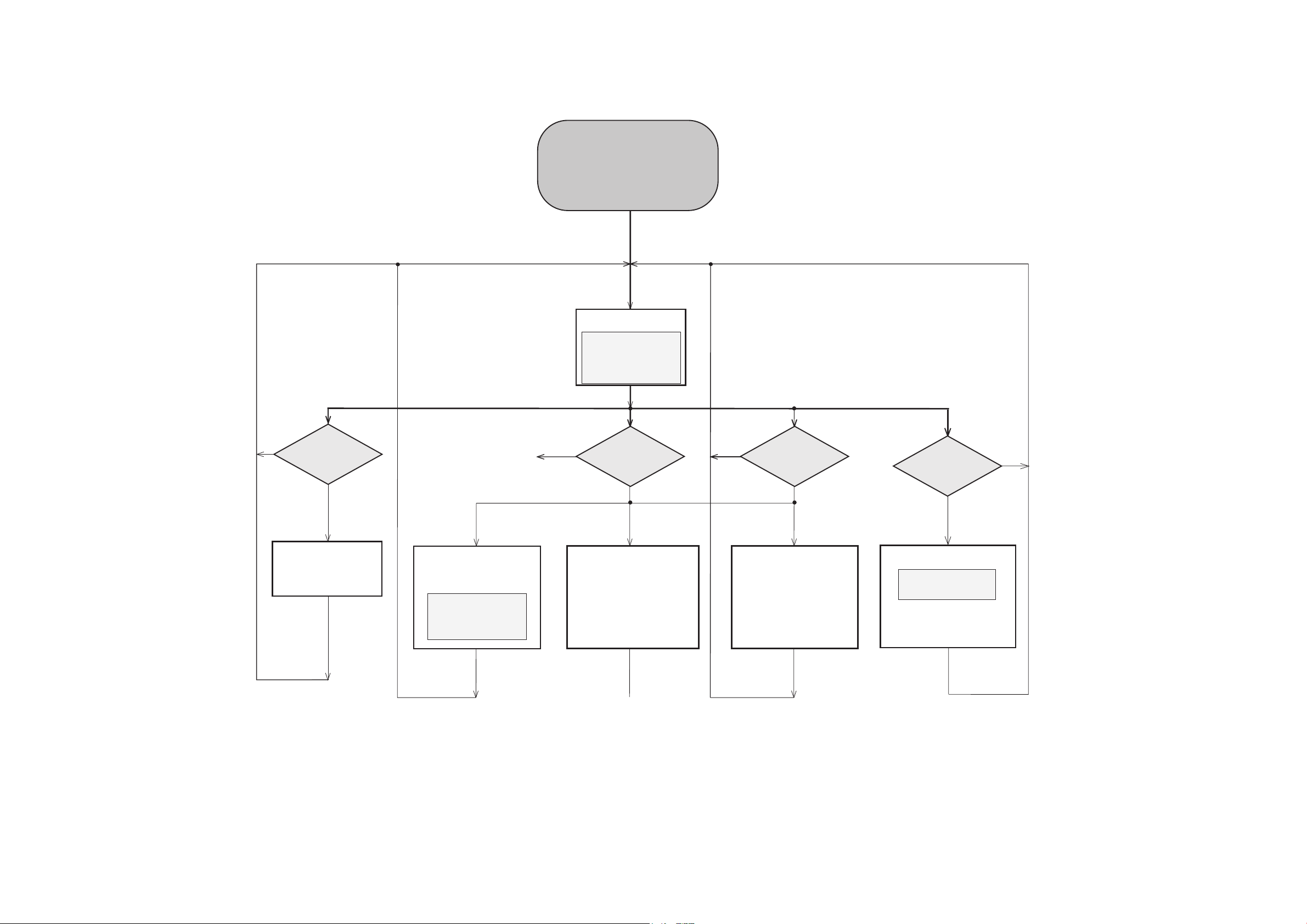
DISPLAY
button pressed?
PLAY
button pressed?
N
Y
Display shows all
segments and flags
for checking open circuits.
DISPLAY TEST FACTORY RESET
VERSION
CHECK
MACROVISION
CHECK
LCD shows “Service”
N
Y
Display shows
EEPROM is cleared and
default values are stored.
This test should be done at the
end of the production process
so that every set is customised
before leaving factory.
Mpeg board super menu
is also display on the
TV screen.
:
The model number is D832.
Software version is V0.04.
Sale region is 98.
Display shows
software version.
V0.02 is the software version,
D832_98_V004
N
Y
CLOCK SET
button pressed?
STOP
button pressed?
Macrovision version
number is display on
the TV screen.
To enter Service Test
program, hold
PLAY & STOP buttons
depressed,and then plug in
D832 V0.02
D832_98_V004
SO3SO3-SLM-791
servo code version:
SOFTWARE VERSION AND UPGRADING
4 - 1
4 - 1
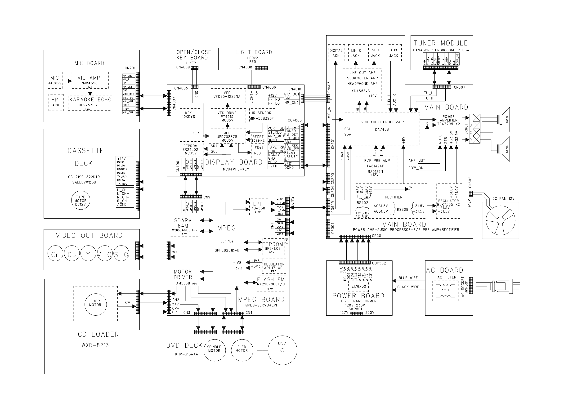
SET BLOCK DIAGRAM
5 - 1 5 - 1
 Loading...