

Philips Dynalite DDBC516FR Installation Manual
features
To reduce the risk of fire or electric shock, do not expose
this device to rain or moisture. Do not energise unless the
front cover is in place. This device must be earthed.
Installation, programming and maintenance must be
carried out by qualified personnel.
Single Phase Supply - 1 phase at 0.15A
5 x Feed thru Outputs Rated at 16A
Power outputs are Latching Relays
Manual Overrides for each channel
Powerful Internal PLC - Custom scripts can be written to
provide process control based on conditional logic
Dry Contact Interface - An Auxiliary dry contact interface is
provided. The factory settings will cause this input to transmit
network identification information
Many Control Options - Control of this device can be via a
combination of methods, eg. serial control port, relay
contacts, push button wall stations, infrared receivers and
time clocks
Simple Installation - DIN Rail mount facilitates installation.
All connection terminals are accessible without disassembly
Warning – This device is a class A product. In a domestic environment this
product may cause radio interference, in which case the user may be required to
take adequate measures.
Read Instructions – We recommend that you read this Instruction Manual prior
to commencement of installation.
Manual Override Switches - These switches do not provide permanent
isolation. Isolate at the supply before performing work on load circuits.
Special Programming – This device will only operate in basic modes unless
programmed via a computer. If programming is required, contact your local
agent for details. Once the data cable is connected to the devices, the factory
default settings will allow any control panel to operate all channels in all
controllers.
Power Sources – This device should only be operated from the type of supply
specified on the front cover. This device must be earthed.
Feed Thru Output Circuits – The load on a circuit should not exceed the
specified capacity of 16A. Loads should be calculated to ensure that the overall
maximum capacity of 80A is not exceeded. This device should be fed via a HRC
fuse or MCB. Output circuits are suitable for Single Phase or Three Phase Star
(with Neutral) only, Delta wiring is not supported.
Mounting Location – Install in a dry, well-ventilated location. Controllers may
emit some mechanical noise. Take this into account when deciding the mounting
location.
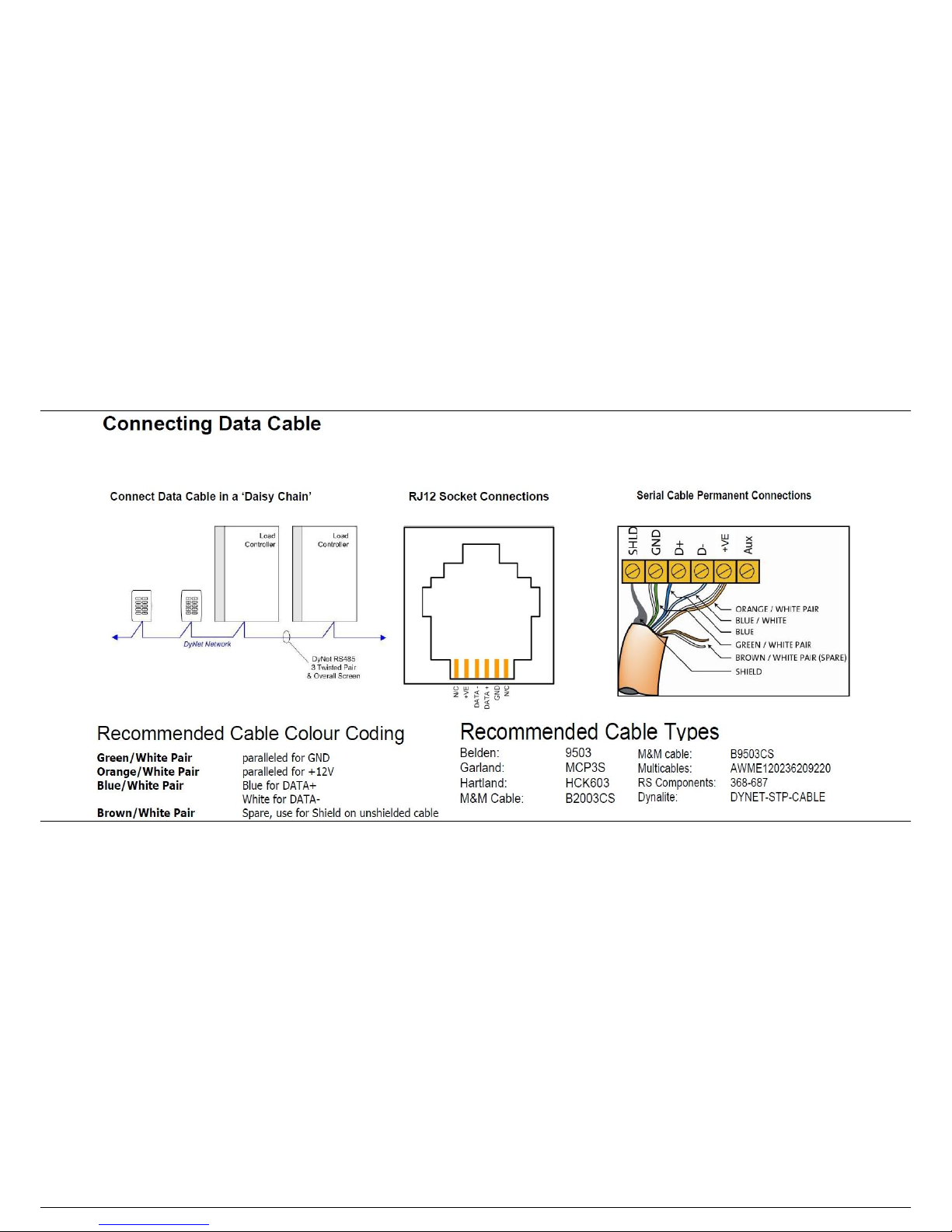
Data Cable – Use screened, stranded RS485 data cable with three twisted pairs.
Segregate from mains cables by 300mm minimum. Connect devices in a ‘daisy
chain’. A data cable that is connected to an energised device is live. Do not cut
or terminate live data cables.
DDBC516FR
5 x 16A relay & Open Protocol Controller
Installation Manual
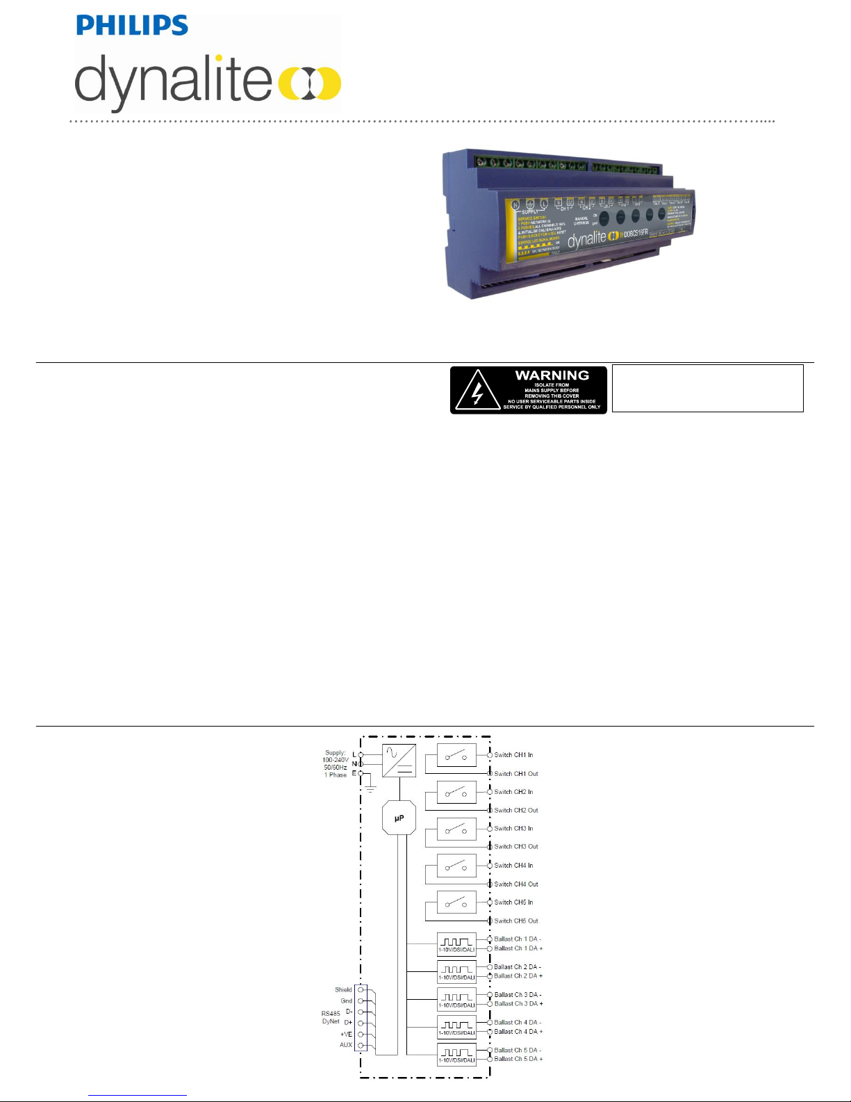
electrical diagram
installation steps
product specifications
1. Mount the device on a DIN rail inside an approved enclosure.
2. Calculate loads to ensure any channels are not overloaded, then connect loads to the output channels. The maximum
loading of this device is as follows:
Maximum Channel Load: 16A 230V AC
Total Box Load: 80A
Connect supply and load cables to each channel. Note that this device must have an individual supply circuit for each
channel. The supply circuits can be on any phase. Note that loads must have a Neutral (1 Phase or 3 Phase Star), Delta
wiring is not supported.
3. 5 x Control Outputs, each selectable to;
- DALI broadcast: max 10 DALI loads per channel.
- DALI addressed: max 10 DALI loads per channel.
- 1-10V: max 10mA Sink or Source per channel.
- DSI: max 10 DSI loads per channel.
4. Connect a single phase 0.15A feed to the control circuit supply terminals. This device must be earthed.
5. Connect data cables to the device as per diagrams below.
6. If the Auxiliary input is to be used, connect a dry contact device in between the AUX and GND terminals. Keep cable runs
between the device and the dry contacts under two metres. The function of the Auxiliary input will need to be programmed
at the time of commissioning.
Control Supply: 230V ±14% 50/60Hz single phase at 0.15A
Load Outputs: 5 x Feed Thru Outputs at 16A per channel, max total box load is 80A
Wiring topology: 1 Phase & Neutral and 3 Phase & Neutral Star. Delta not supported
5 x Open protocol, each selectable to DALI address, DALI Broadcast, 1-10V or DSI
Switching Device: Relay – 50A 230V AC resistive (5000W Lighting Load rated)
Supply Terminals: 1 x Phase, 1 x Neutral 1 x Earth, up to 1 x 4mm2 cable per terminal
Load Terminals: IN, OUT for each channel, up to 1 x 4mm2 cable per terminal
IO: 1 x RS485 DyNet serial port
1 x AUX programmable dry contact input
DyNet DC Supply: 200mA (capacity for approx 5 Panels)
Presets: 170 170
Programmable Logic: 8 Tasks, most UPAN mnemonics supported
Compliance: CE, C-Tick
Ambient Temperature: 50C max.
Construction: Polycarbonate plastic DIN rail mount
Dimensions: Height 93mm x Width 211mm x Depth 75mm
Weight: 0.8Kg
DDBC516FR-DALI Rev B Specifications subject to change without notice
Dynalite manufactured by WMGD Pty Ltd (ABN 33 097 246 921) Unit 6, 691 Gardeners Road Mascot NSW 2020 Australia Tel: +61 2 8338 9899 Fax: +61 2 8338 9333
E-Mail: dynalite.info@philips.com Web: Philips.com/dynalite
 Loading...