

Philips Dynalite DDBC300-DALI Installation Manual
DDBC300-DALI
DALI HF Ballast Controller
Installation Manual
features
Supply – 230V ±14% 50/60Hz Single Phase at 0.1A.
3 x DALI Outputs – Suitable for DALI HF ballasts & transformers.
Built-in DALI Bus Power Supply – No external supply required.
Dry Contact Interface – Can be programmed to perform many
different functions. The factory settings will cause this input to
transmit network identification information.
Many Control Options – Control of this device can be via a
combination of methods eg. Serial control port, push button
control panels, infrared receivers and timeclocks.
Simple Installation – DIN Rail mount facilitates installation.
All connection terminals accessible without disassembly.
Special Programming – This device will only operate in basic modes
unless programmed via a computer. If programming is required, contact
your local agent for details. Once the data cable is connected to the
devices, the factory default settings will allow any control panel to control
all channels in all dimmers.
Check Connections – Tighten all load-carrying screw connections, as
vibrations from transport can cause terminal block screws to become
loose.
Power Sources – This device should only be operated from the type of
supply specified on the front cover. This device must be earthed.
Load Control Circuit – A 2 core DALI bus cable is required to be run to
the loads, this cable is in addition to the mains feed.
Load Type – This product is intended to control DALI devices.
Mounting Location – Install in a dry, well-ventilated location. Controllers
may emit some mechanical noise. Take this into account when deciding
the mounting location.
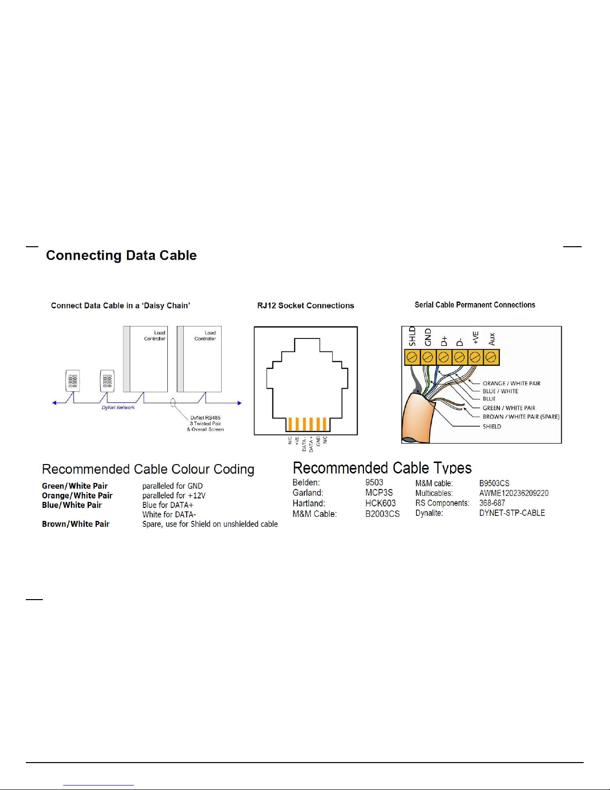
Data Cable – Use screened, stranded RS485 data cable with three
twisted pairs. Segregate from mains cable by 300mm minimum. Connect
devices in a ‘daisy chain’. A data cable connected to an energized
device is live. Do not cut or terminate live data cables.
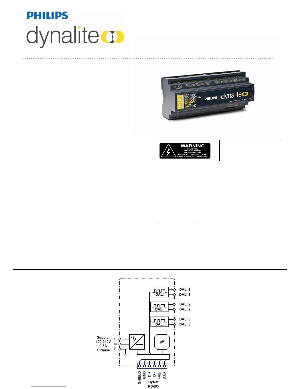
electrical diagram
To reduce the risk of fire or electric shock, do
not expose this device to rain or moisture. Do
not energise unless the front cover is in place.
The device must be earthed. Installation,
programming and maintenance must be carried
out by qualified personnel.
product specifications
connecting data cable
Supply:
100 – 240V 50/60Hz Single Phase at 0.5A
Control Output:
3 x DALI Control Outputs, each supporting a full DALI universe of 64 channels (192 total), including backward
channel
Supply Terminals:
Line, Neutral, Earth 1 x 4mm2 max conductor size
DALI Terminals:
3 x Ballast DALI circuit - Dx, Dx - 1 x 4mm2 max conductor size
Control Inputs:
1 x RS485 DyNet serial port
1 x AUX programmable dry contact input
DALI BUS DC Supply:
Integral 24V 250MA power supply
DyNet DC Supply:
200mA (Supply for approx 10 panels)
Preset Scenes:
170
Compliance:
CE, C-Tick
Operating Environment:
0° to 40°C ambient temperature
0% to 90% RH non-condensing
Construction:
Polycarbonate DIN rail mount
Dimensions:
H 93mm x W 211mm x D 75mm
Weight:
0.49kg
DDBC300-DALI Instruction Manual Rev E Specifications subject to change without notice
Dynalite manufactured by WMGD Pty Ltd (ABN 33 097 246 921) Unit 6, 691 Gardeners Road Mascot NSW 2020 Australia Tel: +61 2 8338 9899 Fax: +61 2 8338 9333
E-Mail: dynalite.info.@philips.com Web: Philips.com/dynalite
installation steps
1. Mount the device on a DIN rail inside an approved enclosure.
2. Connect mains cables: Connect a 0.1A single phase supply to the Supply terminals, this will operate the product’s
electronics. This device must be earthed.
3. Connect the DALI bus cables: Use a mains rated 2 core cable to connect the DALI bus to the DALI ports on all DALI
devices. The DALI bus cable should not be longer than 300 Metres, and should have a minimum cross section area
based on cable length as follows:
- Up to 100 Metres: 0.5mm2
- 100 to 150 Metres: 0.75mm2
- 150 to 300 Metres: 1.5mm2
The DALI bus is not SELV and must be treated as a mains cable. It is not polarity conscious. A maximum of 64 DALI
devices can be wired to each DALI port.
4. Connect data cables to the device as per diagrams below. Segregate data cables from mains cables.
5. If the Auxiliary input is to be used, connect a dry contact device in between the AUX and GND terminals. Keep cable
runs between the AUX terminals and the dry contacts under two metres. The function of the Auxiliary input will need
to be programmed at the time of commissioning.
 Loading...