

Philips Dynalite DDBC1200 Installation Instructions Manual
DDBC1200
Overview
• Single-phase supply – 100 - 240 VAC at 0.5A
• 12 individually controlled lighting driver channels – each
Broadcast
• High output capacity – each of the 12 channels is capable of
driving the following:
DALI: max 80 drivers per channel or 300 total
DSI: max 100 drivers per channel or 375 total
0-10V: 50mA sink or source per channel
• LED status indicators and override switches – for each of the
12 outputs
• Powerful internal PLC – allows custom scripts to enable process
control based on conditional logic
• Dry contact interface – factory settings enable this interface to
• Many control options – device is controllable via a combination of
methods, including a serial control port, relay contacts, push-button
wall stations, infrared receivers and timeclocks
Signal Dimmer Controller
Read Instructions – We recommend that you read this guide prior
to commencement of installation.
Special Programming – Once powered and terminated correctly
this device will only operate in basic mode. If network terminations
are correct, a new Dynalite user interface turns all lighting channels
on from button 1 and off from button 4. Commissioning can only
begin once the full network has been tested. Advanced functions
are commissioned via Envision software. If commissioning services
are required, contact your local distributor.
Check Connections – Tighten all load-bearing screw connections,
as vibrations from transport can cause the terminal block screws to
loosen.
Power Sources – This device must only be powered by the supply
Output Circuits – The load on each circuit must not exceed the
or 50mA sink or source for 1-10V.
Mounting Location – Install in a dry, well-ventilated location.
Controllers may emit some mechanical noise. Take this into
account when deciding the mounting location.
Data Cable – Use screened, stranded RS485 data cable with three
twisted pairs. Segregate from mains cables by at least 300mm.
is connected to an energized device is live. Do not cut or terminate
live data cables.
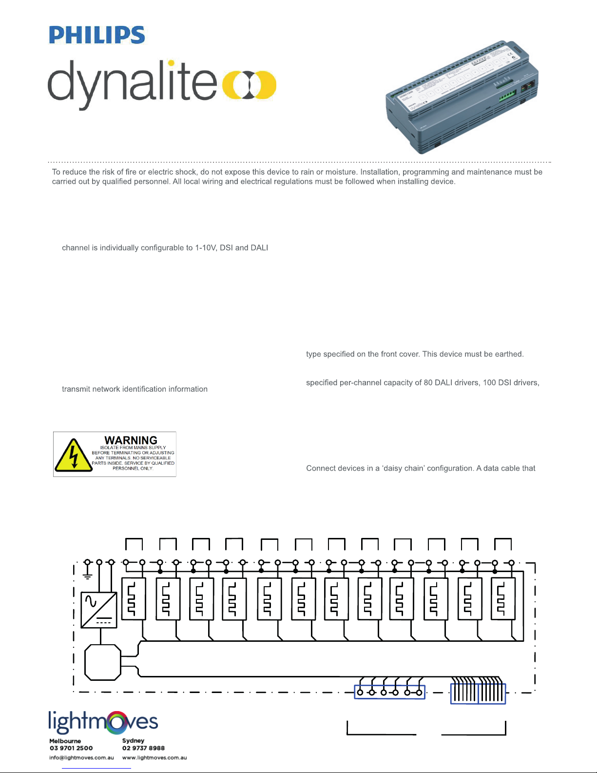
Electrical Diagram
Supply:
100 – 240 VAC
0.5A
E
µ
P
N
L
DA+
CH2
CH3
CH4
CH5
CH6
CH7
CH8
CH9
CH10
CH11
CH12
DA-
+
V
E
D
+
D
-
G
N
D
S
h
i
e
ld
A
U
X
DyNet
RS485
2 x RJ12
CH1
DA+
DA-
DA+
DA-
DA+
DA- DA+
DA- DA+DA- DA+
DA-
DA+DA-
DA+
DA-
DA+
DA-
DA+
DA-
DA+DA-
D
A
L
I
1
-
1
0
V
D
S
I
D
A
L
I
1
-
1
0
V
D
S
I
D
A
L
I
1
-
1
0
V
D
S
I
D
A
L
I
1
-
1
0
V
D
S
I
D
A
L
I
1
-
1
0
V
D
S
I
D
A
L
I
1
-
1
0
V
D
S
I
D
A
L
I
1
-
1
0
V
D
S
I
D
A
L
I
1
-
1
0
V
D
S
I
D
A
L
I
1
-
1
0
V
D
S
I
D
A
L
I
1
-
1
0
V
D
S
I
D
A
L
I
1
-
1
0
V
D
S
I
D
A
L
I
1
-
1
0
V
D
S
I
Supplied by:

DDBC1200 Installation Instructions Rev 08 Specications subject to change without notice
Dynalite manufactured by WMGD Pty Ltd (ABN 33 097 246 921) Unit 6, 691 Gardeners Road Mascot NSW 2020 Australia Tel: +61 2 8338 9899 Fax: +61 2 8338 9333
E-Mail: support.controls@philips.com Web: http://philips.com/dynalite
Supply: 100 - 240 VAC 50/60 Hz single phase at 0.5A
Control Outputs: 12 x HF Driver control outputs, each selectable to DALI Broadcast, 1-10V or DSI
Control Capacity: DALI Broadcast: max 80 drivers/channel, do not exceed 300 drivers total
DSI: max 100 drivers per channel, do not exceed 375 drivers total
1-10V: 50mA sink or source
Supply Terminals: 1 x Earth, 1 x Neutral 1 x Phase
conductor size 0.2 - 5mm2 (24 - 10 AWG)
Output Terminals: 12 x DALI, 0-10V, DSI driver circuits: DA+, DA-
conductor size 0.2 - 5mm2 (24 - 10 AWG)
User Controls: Manual override switch for each channel, Service switch, Diagnostic LED, programmable AUX input
Serial Port: 1 x RS485 unterminated, consisting of:
2 x RJ12 sockets
1 x 6 way terminal strip for permanent connections (2.5mm2 conductor size)
DyNet DC supply: 12 V @ 200 mA (supply for approx. 9 user interfaces)
Presets: 170
Compliance: CE, RCM
Operating Conditions: Temperature: 0 to 40° C ambient
Humidity: 0 to 95% non-condensing
Storage & Transport: Temperature: -25 to 70° C ambient
Humidity: 0 to 90% non-condensing
Construction: Polycarbonate DIN-rail mount
Dimensions: 93 mm x 215 mm x 64 mm (3.6” x 8.5” x 2.5”)
Packed Weight: 0.54 kg
Installation Steps
1. Mount the device on a DIN-rail inside an approved enclosure.
2. Calculate loads to ensure any channels are not overloaded, then connect loads to the output channels. The maximum loading of this
device is as follows:
DALI Broadcast mode: max 80 drivers per channel or 300 total
DSI Mode: max 100 drivers per channel or 375 total
1-10V mode: 50mA sink or source
Note that most 1-10V cabling scenarios are polarity-dependent. DALI and DSI cables are not polarity-dependent.
3. Connect a single phase 0.5A feed to the supply terminals. Ensure that the DDBC1200 is earthed.
4. Connect data cables to the device as per the diagrams below.
5. If the auxiliary dry contact input is to be used, connect a dry contact device between the AUX and GND terminals. Keep cable
runs between the DDBC1200 and the dry contact under two meters. The function of the auxiliary input is congurable via the
EnvisionProject commissioning software.
Note that correct operation of DALI Broadcast mode relies on the drivers being set to their factory defaults.
If problems are encountered, press the DDBC1200 service switch 3 times to reset all connected and energized drivers to their default
settings.
Recommended Cable Type
Dynalite DYNET-STP-CABLE or equivalent shielded
four twisted-pair.
See datasheet for more information.
Recommended Cable Color Coding
Green/White Pair Paralleled for GND
Orange/White Pair Paralleled for +12VDC
Blue/White Pair Blue for DATA+
White for DATA-
Brown/White Pair Spare, use for SHIELD on unshielded cables
SHLD
GND
D+
D-
+12V
Aux
Shield
Green/Green white
Blue
Blue white
Orange/Orange white
Brown/Brown white
+VE
+VE
D –
D +
GND
GND
RS485 DyNet network
Product Specications
 Loading...