

Philips dynalite DBC1210 Installation Manual
DBC1210
12 x 10A HF Ballast Controller
Installation Manual
contents
Warning……………………………………………..
2
Hardware Controls…………………………….…..
7
Features……………………………………………..
2
Troubleshooting…………………………………….
8
Important Safeguards……………………………..
2
Specication……………………………….……….
8
Internal View………………………………………..
3
Mounting…………………………………….………
4
Supply & Load Cable Connections.……………… 5
Connecting Serial Control Cables………………..
6
Supplied by:

2 DBC1210 Installation Manual Rev N.docx
features
Three Phase Supply
3 phase and neutral at 40A per phase.
12 Switched Outputs
Each 10A output is switched via a high
specification relay with specially treated
contacts which prevent contact fusion when
switching very reactive loads.
12 Control Outputs
Each of the 12 optically isolated outputs can
be configured to be either 1-10V, DSI or
DALI serial control, covering the latest types
of HF Fluorescent Ballasts. Also compatible
with 1-10V, DSI and DALI dimmable
electronic transformers.
MCB Protection
Each mains output is protected by a single
pole magnetic circuit breaker.
Many Control Options
Control of this device can be from a
combination of methods, eg. serial control
port, relay contacts, push button wall
stations, infra red receivers and timeclocks.
Easy high-level interface to other popular AV
control systems and Building Management
Systems (BMS) is also available.
Simple Installation
Wall-mount enclosure with mounting lugs
facilitates installation. Cable knockouts are
provided at the top and right hand side of
the enclosure for supply and load cables,
with low voltage (LV) control at the bottom.
important safeguards
Warning – This is a class A product. In a domestic
environment this product may cause radio interference in
which case the user may be required to take adequate
measures.
Read Instructions – We recommend that you read this
instruction manual prior to commencement of installation.
Retain instructions and give the end user
Troubleshooting - If problems are encountered, check
the troubleshooting section on page 8.
Special Programming – Once powered and terminated
correctly this device will only operate in basic mode. A
new Dynalite panel will turn on all lighting channels from
button 1 and turn off from button 4 if network terminations
are correct. Only once the full network is test correct can
commissioning begin. Advanced functions can be
commissioned via Envision software. If commissioning is
required, contact your local distributor for details.
Check Connections – Treat this device as a
switchboard that has been shipped. Tighten all loadcarrying screw connections, as vibrations from transport
can cause MCB and terminal block screws to become
loose.
Power Sources – This device should only be operated
from the type of supply specified on the front panel. This
device must be earthed.
Output Circuits – The load on a circuit should not
exceed the specified capacity of 10A. Loads should be
calculated to ensure that the overall maximum capacity of
120A is not exceeded.
Load Control Circuits – If this device is being used to
control 1-10V, DSI or DALI HF fluorescent ballasts, a 2
core mains rated control cable is required to be run to the
loads, in addition to the mains feed.
Load Type – Default settings are for load control outputs
to be DSI. Check to see what type of HF Fluorescent
Ballasts are in the luminaries. Do not terminate the
control lines to any DALI or DSI loads until the relevant
channel has been programmed appropriately. When
connecting 1-10V load control lines, pay attention that the
correct polarity is maintained.
Megger Testing – Do not megger test any circuitry
connected to the dimming system, as damage to the
electronics may result.
Mounting Location – This device must be mounted right
way up, on a vertical surface (refer to page 4 for
mounting instructions). The specified minimum clearance
of 100mm for all sides must be adhered to. Install in a
dry, well-ventilated location. Controllers may emit some
mechanical noise. Take this into account when deciding
the mounting location.
Data Cable – The recommended cable for connections to
the serial port is screened, stranded RS485 data cable
with three twisted pairs. Part numbers for various
manufacturers are listed on page 6. This cable should be
segregated from mains cables by a minimum distance of
300mm. If anticipated cable runs are over 600 metres for
serial cables, consult your dealer for advice. Do not cut or
terminate live data cables.
Warning
TO REDUCE THE RISK OF FIRE OR
ELECTRIC SHOCK, DO NOT EXPOSE
THIS DEVICE TO RAIN OR MOISTURE.
DO NOT ENERGISE UNLESS THE
FRONT COVER IS IN PLACE.
THIS DEVICE MUST BE EARTHED.
INSTALLATION, PROGRAMMING AND
MAINTENANCE MUST BE CARRIED
OUT BY QUALIFIED PERSONNEL
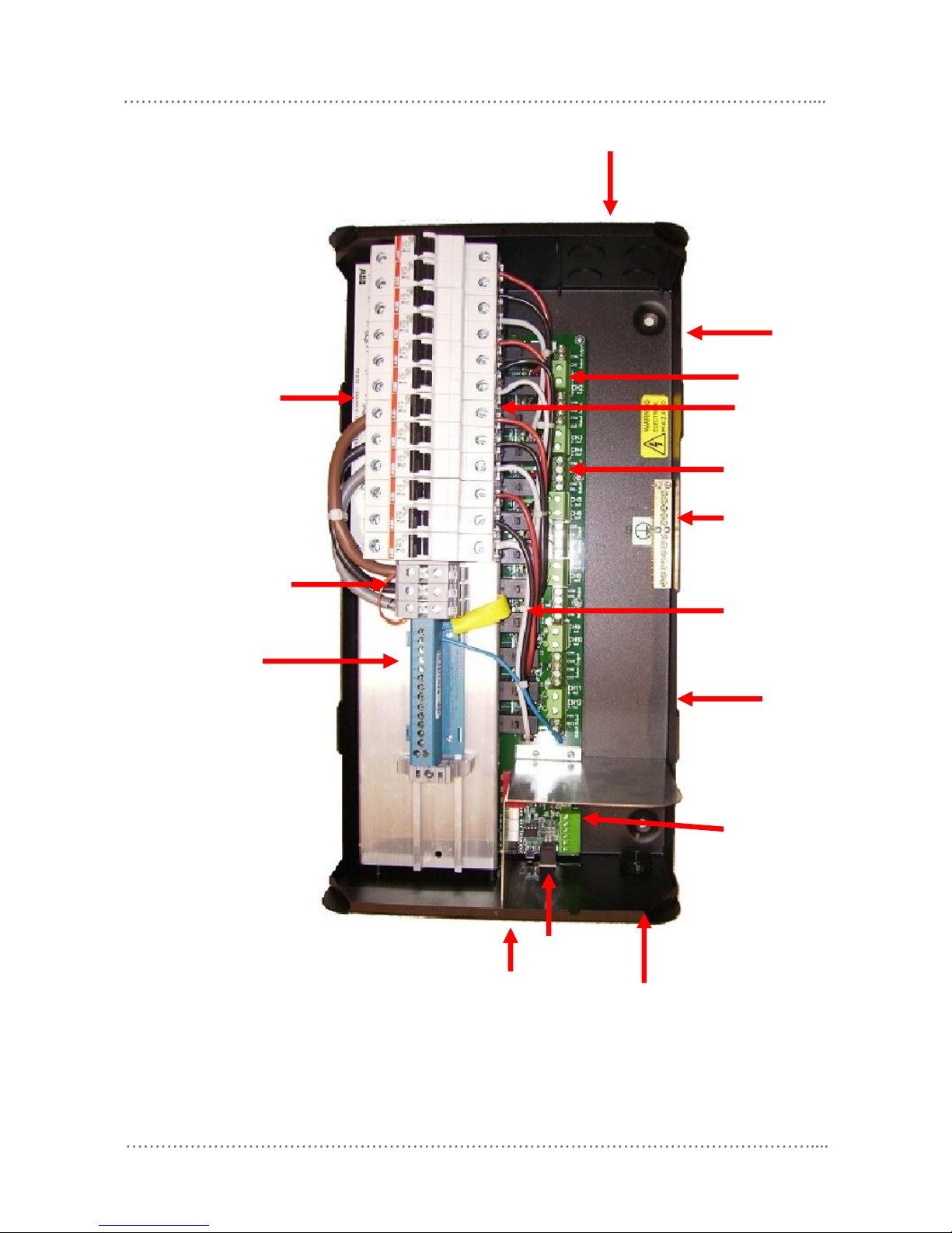
internal view
DBC1210 Installation Manual Rev N.docx 3
For spare parts, please call your nearest Dynalite Customer Service Centre, and specify DBC1210
Dynet Data
Cable
Terminal
Earth Link
Data Entry
Cable
Neutral Link
Network
Socket
Supply or Load
Cable Entry
Manual Circuit
Breakers
Service LED &
service switch
3 phase
Supply terminals
Load Cable Entry
Load Cable Entry
Power switch output
Dimmer control signal
1-10V, DSI or DALI
Channel over ride
switch
Emergency lighting
supply
 Loading...