

Page 1
DVD782CH
Hookup Pages
Read this manual first!
Congratulations on purchasing this product. We’ve included everything you
need to get started. If you have any problems, our Representatives can help
you get the most from your new product by explaining:
• Hookups,
• First Time Setup, and
• Feature Operation.
Do not attempt to return this product to the store.
For fast help, call us first!
1-800-531-0039
Thank you for making us a part of your home!
Page 2

8 Hookups
Depending on your TV and other equipment you wish to connect, there are various ways
you could connect the DVD Changer. Use only one of the connections described on pages
9-12.
Before you begin...
● Refer to the manuals of your TV, Stereo, Receiver or other devices as necessary. Note
the style of jacks and connectors on the other equipment. Determine how to choose
different Audio and VIdeo In channels on your other equipment so you can see and hear
the DVD Changer on the TV, Stereo, etc.
● Disconnect all equipment from the power outlets. Connect the equipment to the power
outlets only after you have finished hooking up everything. Never make or change connections with equipment connected to the power outlet.
● Depending on your connection, you may need to purchase additional cables.
Determining the best possible connection...
Your hookup will be determined primarily by feature availability of your existing equipment.
However, the following guidelines describe which options have the best picture and sound
quality.
Use the Component Video jacks for the best picture quality.
Use the S-Video jack for excellent picture quality.
Use the yellow Video jack for good picture quality.
If your TV only has an RF-style jack, usually labeled Antenna In or 75 ohm, you
will need an adapter in order to connect the DVD Changer to the TV. Ask your
electronics retailer for details. The DVD picture still will exceed the quality of
videotapes and other analog recordings.
Digital audio connections provide the clearest sound. Connect one of the DVD
Changer’s DIGITAL AUDIO OUT jacks (COAXIAL or OPTICAL) to your
Receiver for the best sound quality.
If digital connections are not possible, connect the DVD Changer’s red and white
AUDIO OUT jacks to the Audio In jacks of your Receiver or TV. Using the red
and white cables provides a standard “analog” or “two-channel” connection.
Sound is distributed through two channels, or the Left and Right channels.
Remember...
● Connect the DVD Changer directly to the TV. For example, do not connect the
DVD Changer to a VCR, then connect the VCR to a TV. This type of connection may
distort the picture and sound. Also, your VCR might have the copy protection system,
which could further distort the DVD image.
● Set the TV to the correct Video In channel. Such channels may be called AUX or
AUXILIARYIN, AUDIO/VIDEO or A/V IN, EXT1 or EXT2, etc. These channels often
are located near channel 00. See your TV owner’s manual for details.
● Set the audio equipment (Amplifier, Receiver, etc.) to the correct channel or
“source” mode.
● Do not connect the DVDChanger’s AUDIO OUT jack to the PHONO IN jack of your
audio system.
● You only need one audio connection and one video connection.
● If you connect the DVD Changer to a Receiver that is Dolby Digital and DTS compati-
ble, set Dolby Digital or DTS to On at the DVD Changer. Details are on pages 40-41.
● If your Receiver is not Dolby Digital or DTS compatible, set Dolby Digital or DTS to
Off at the DVD Changer. Playing a DVD when the settings are wrong will distort the
sound or damage the speakers.
Once you determine the best option, find your choice on pages 9-12. Follow
the specific steps for the hookup you chose.
Page 3
Hookups (cont’d) 9
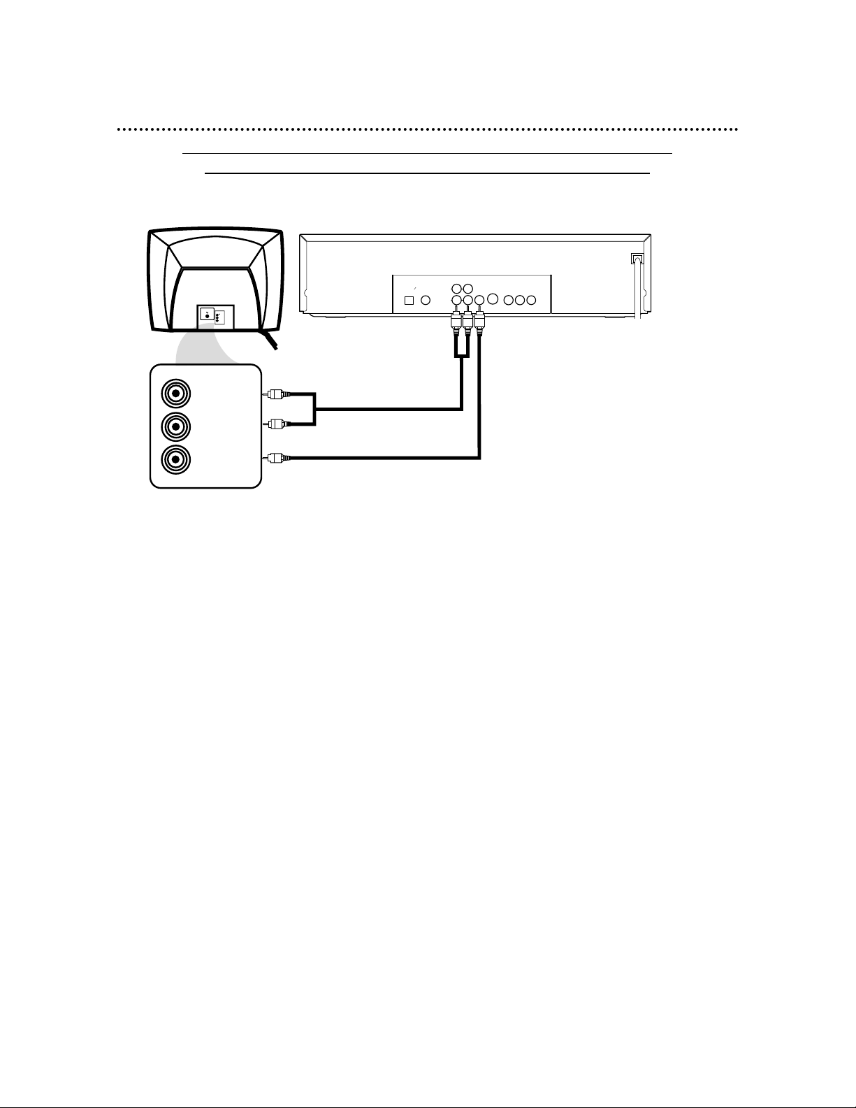
Connecting the DVD Changer to a TV only (no stereo or Receiver)
TV has AUDIO (red and white) and VIDEO (yellow) IN jacks
DIGITAL AUDIO OUT
OPTICAL
COAXIAL
PCM
BITSTREAM
VIDEO
OUT
RL
AUDIO OUT
1
2
S–VIDEO
OUT
Y
Pb/Cb
Pr/Cr
COMPONENT VIDEO OUT
VIDEO
L/MONO
AUDIO
R
in
1
VIDEO IN
LEFT AUDIO IN
RIGHT AUDIO IN
1
Connect the supplied red and white audio cables to the red and white AUDIO OUT jacks
(either 1 or 2) on the DVD Changer and to the red and white AUDIO IN jacks on the TV.
Match the cable colors to the jack colors. If your TV’s AUDIO IN jacks are not colored, match Left to Left
and Right to Right.
2
Connect the supplied yellow video cable to the VIDEO OUT jack on the DVD Changer and to
the VIDEO IN jack on the TV.
3
Connect the TV’s power cord to a power outlet.
Turn on the TV and set it to the Audio/Video In channel. This may be referred to as A/V In,
Auxiliary In, EXT or External In, Video In, or Source. This channel may be near channel 00. See your TV
manual for details.
4
Connect the DVD Changer’s power cord to a power outlet.
Press the POWER button to turn on the DVD Changer. “P-ON” will appear briefly on the DVD
Changer’s display panel. You should see the DVD logo on the TV screen. If you do not, check your connections and make sure the TV is set to the correct Audio/Video In channel. If you still do not see the
DVD logo or DVD playback, continually change the TV channel until you see the DVD image on the TV.
1
2
Back of TV
(example only)
DVD Changer
Page 4

10 Hookups (cont’d)
Connecting the DVD Changer to a TV only (no stereo or amplifier)
TV has audio (red and white) and S-Video In jacks
DIGITAL AUDIO OUT
OPTICAL
COAXIAL
PCM
BITSTREAM
VIDEO
OUT
RL
AUDIO OUT
1
2
S–VIDEO
OUT
Y
Pb/Cb
Pr/Cr
COMPONENT VIDEO OUT
S-VIDEO IN
LEFT AUDIO IN
RIGHT AUDIO IN
VIDEO
L/MONO
AUDIO
R
in
1
1
Connect the supplied red and white audio cables to the red and white AUDIO OUT jacks
(either 1 or 2) on the DVD Changer and to the red and white AUDIO IN jacks on the TV.
Match the cable colors to the jack colors. If your TV’s AUDIO IN jacks are not colored, match Left to Left
and Right to Right.
2
Connect an S-Video cable (not supplied) to the S-VIDEO OUT jack on the DVD Changer and
to the S-VIDEO IN jack on the TV.
3
Connect the TV’s power cord to a power outlet. Turn on the TV and set it to the S-VIDEO
IN channel. This channel may be near channel 00. See your TV owner’s manual for details.
4
Connect the DVD Changer’s power cord to a power outlet.
Press the POWER button to turn on the DVD Changer. “P-ON” will appear briefly on the DVD
Changer’s display panel. You should see the DVD logo on the TV screen. If you do not, check your connections and make sure the TV is on the correct S-Video In channel. If you still do not see the DVD logo
or DVD playback, continually change the TV channel until you see the DVD image on the TV.
1
2
Back of TV
(example only)
DVD Changer
Page 5

Hookups (cont’d) 11
Connecting to a TV and a Stereo
TV has Component Video In Jacks
DIGITAL AUDIO OUT
OPTICAL
COAXIAL
PCM
BITSTREAM
VIDEO
OUT
RL
AUDIO OUT
1
2
S–VIDEO
OUT
Y
Pb/Cb
Pr/Cr
COMPONENT VIDEO OUT
VIDEO
L/MONO
AUDIO
R
in
1
AUDIO (RIGHT) IN
AUDIO (LEFT) IN
Y
Cb/B-Y
Cr/R-Y
COMPONENT
VIDEO IN
1
Connect the supplied red and white audio cables to the red and white AUDIO OUT jacks (either
1 or 2) on the DVD Changer and to the red and white AUDIO IN jacks on the Stereo. Match the
cable colors to the jack colors. If your Stereo’s AUDIO IN jacks are not colored, match Left to Left and
Right to Right.
2
Connect optional component video cables to the COMPONENT VIDEO OUT jacks on the DVD
Changer and to the COMPONENT VIDEO IN jacks on the TV. Refer to your TV manual. The TV’s
jacks may be labeled differently than the picture above.
3
Plug in the Stereo’s power cord. Turn on the Stereo and select the Stereo’s Auxiliary IN station.
Your Stereo may refer to this as Source or AUX IN. During Disc playback, you will adjust the volume at your
Stereo. See your Stereo owner’s manual for details.
4
Plug in the TV’s power cord. Turn on the TV and set it to the Component Video In channel,
which might be near channel 00. During Audio CD playback, you may check the status of Audio CDs on
your TV screen. During DVD playback, you will watch the program on the TV. See your TV manual for details.
5
Connect the DVD Changer’s power cord to a power outlet.
Press the POWER button to turn on the DVD Changer. “P-ON” will appear briefly on the DVD
Changer’s display panel. You should see the DVD logo on the TV screen. If you do not, check your connections and make sure the TV is on the correct Component Video In channel. If you still do not see the DVD
logo or playback on the TV, keep changing TV channels until you see the DVD image on the TV.
2
1
Back of TV
(example only)
Stereo
(example only)
DVD Changer
Page 6

12 Hookups (cont’d)
Connecting to a TV and a Dolby Digital or DTS-compatible Receiver
DIGITAL AUDIO OUT
OPTICAL
COAXIAL
PCM
BITSTREAM
VIDEO
OUT
RL
AUDIO OUT
1
2
S–VIDEO
OUT
Y
Pb/Cb
Pr/Cr
COMPONENT VIDEO OUT
VIDEO
L/MONO
AUDIO
R
in
1
VIDEO IN
COAXIAL DIGITAL
AUDIO IN
● Some Discs are recorded in 5.1 channel Dolby Digital Surround or Digital Theater System (DTS) Surround
format. These Discs sound best when played through a Receiver that is Dolby Digital or DTS compatible.
● You will need a coaxial digital audio cable or an audio optical cable (not supplied).
● If you use the OPTICAL jack, remove the protective cap first.
● Select 5.1 channel Dolby Digital Surround sound in the Disc menu, if available.
● Connect a subwoofer and speakers to the Receiver as described in the Receiver’s manual.
1
Connect a coaxial digital audio cable to the COAXIAL jack on the DVD Changer and to the
COAXIAL DIGITAL AUDIO IN jack on the Receiver. (Or, you may connect an audio optical cable to
the OPTICAL jack on the DVD Changer and to the OPTICAL DIGITAL AUDIO IN jack on the Receiver.
Only one audio connection is needed.)
2
Connect the supplied yellow video cable to the yellow VIDEO OUT jack on the DVD Changer
and to the VIDEO IN jack on the TV. (Or, you may connect component video cables to the COMPO-
NENT VIDEO OUT jacks on the DVD Changer and to the COMPONENT VIDEO IN jacks on the TV. Or,
connect an S-Video cable to the S-VIDEO OUT jack on the DVD Changer and to the S-VIDEO IN jack on the
TV. Only one video connection is needed. See pages 9-11 for video connection options.)
3
Plug in the Receiver’s power cord. Turn on the Receiver and select the Auxiliary IN or DVD station. This may be referred to as Source, External Input, etc. During Disc playback, you will adjust the volume
at the Receiver. See your Receiver manual for details.
4
Plug in the TV’s power cord. Turn on the TV and set it to the correct Video In channel. During
Audio CD playback, you may check the Disc status on your TV screen. During DVD playback, you will watch
the program on the TV. See your TV owner’s manual for details.
5
Connect the DVD Changer’s power cord to a power outlet. Press the POWER button to turn on
the DVD Changer. “P-ON” will appear briefly on the DVD Changer’s display panel. You should see the
DVD logo on the TV. If you do not, check your connections and make sure the TV is on the correct channel. If
you still do not see the DVD logo or playback on the TV, keep changing TV channels until you see the DVD
image on the TV.
1
2
Receiver
(example only)
Back of TV
(example only)
DVD Changer
Page 7

14 Front Panel
OPEN/CLOSE Button
Press to open or close the Disc
tray. Details are on page 18.
PLAY Button
Press to start or resume regular
Disc playback. Details are on page 18.
STOP Button
Press to stop Disc playback.
Details are on page 18.
STANDBY-ON Button
Press to turn the power on and off
(Standby). Details are on page 18.
Remote Sensor
Receives a signal from
your remote control so
you can operate your
DVD Changer from a
distance.
PREV(ious) Button
Press once to go to the beginning
of the current Track/Chapter.
Press repeatedly to go to previous Tracks/Chapters. Press and
hold for three seconds for a fast
reverse search during playback.
Details are on page 22.
NEXT Button
Press to go to subsequent Tracks
or Chapters. Press and hold for
about three seconds for a fast
forward search during playback.
Details are on page 22.
DISC SELECT Button
Press to rotate the Disc tray clockwise by one. For example,
if Disc 3 is selected and you press the DISC SELECT button
once, Disc 4 will be selected next. Details are on page 18.
DISC Number (1-5) Buttons
When the tray is closed, press to select a
specific Disc tray for playback. When the
tray is open, press to bring a specific disc
tray to the front left side for loading or
unloading. Details are on page 18.
Page 8

Rear Panel 15
DIGITAL AUDIO OUT
OPTICAL
COAXIAL
PCM
BITSTREAM
VIDEO
OUT
RL
AUDIO OUT
1
2
S–VIDEO
OUT
Y
Pb/Cb
Pr/Cr
COMPONENT VIDEO OUT
COAXIAL Jack
Connect an optional audio coaxial
digital cable here and to the coaxial
digital Audio In jack of a Receiver.
Details are on page 12.
S-VIDEO OUT Jack
Connect an optional S-Video cable here
and to the S-Video In jack of a television.
Details are on pages 10 and 12.
VIDEO OUT Jack
Connect the yellow video cable
(supplied) here and to the TV’s
Video In jack. Details are on
pages 9 and 12.
AUDIO OUT Jacks
Connect the supplied red
and white audio cables here
and to the Audio In jacks of
a television or Receiver.
Details are on pages 9-11.
OPTICAL Jack
Connect an optional audio optical cable here
and to the Optical Digital Audio In jack of a
Receiver. Details are on page 12.
When the OPTICAL jack is not in use, make
sure its protective cap is in place.
COMPONENT VIDEO OUT Jacks
Connect optional component video cables
here and to the component Video In jacks
of a television. This video connection
provides the best picture. Use it if possible
(if your TV has COMPONENT VIDEO IN
jacks). Details are on pages 11-12.
• You only need one audio connection and one
video connection, so you will not have a cable
connected to every jack. For example, if you
are using the S-VIDEO OUT jack, you will not
use the yellow VIDEO OUT jack or the
COMPONENT VIDEO OUT jacks.
Helpful Hint
AC Power Cord
Connect to a standard AC
outlet to supply power to
the DVD Changer.
 Loading...