

Page 1

DVD-Video Player DVD703 /XX1
DVD703 /031 /691 /751 /781
Contents Page
1 Technical specifications and connection facilities 2
2 Warnings, laser safety instructions and notes 3
3 Directions for use 6
4 Mechanical instructions and exploded views 15
5 Diagnostic software descriptions and
troubleshooting 20
Block- and wiring diagram
6
Blockdiagram 39
Wiring diagram 40
7
Electrical diagrams and print-layouts Diagram PWB
Power supply 41 42-43
A/V Board Video control (Diagram A1) 44 46-47
A/V Board Audio (Diagram A2) 45 46-47
Display panel (Diagram D) 48 49
Bare board Standby 50 50
8 Electrical alignments 51
9 Circuit descriptions and 51
List of abbreviations 54
10 Spare part list 55
CL 16532007_071.eps
140201
©
Copyright 2001 Philips Consumer Electronics B.V. Eindhoven, The Netherlands.
All rights reserved. No part of this publication may be reproduced, stored in a
retrieval system or transmitted, in any form or by any means, electronic, mechanical,
photocopying, or otherwise without the prior permission of Philips.
Published by MW 0162 Service PaCE Printed in the Netherlands Subject to modification 5 3122 785 11100
Page 2

GB 2 DVD703 /XX11.
Technical specifications
1. Technical specifications
Specifications
PLAYBACK SYSTEM
DVD-Video
Video CD & SVCD
CD (CD-Recordable and CD-Rewritable)
DVD+RW
OPTICAL READOUT SYSTEM
Lasertype Semiconductor AlGaAs
Numerical Aperture 0.60 (DVD)
Wavelength 650 nm (DVD)
DVD DISC FORMAT
Medium Optical Disc
Diameter 12cm (8cm)
Playing time One layer 2.15 h*
(12cm) Dual layer 4 h*
VIDEO FORMAT
DA Converter 10 bits
Signal handling Components
Digital Compression MPEG2 for DVD,
TV STANDARD (PAL/50Hz) (NTSC/60Hz)
Number of lines 625 525
Playback Multistandard (PAL/NTSC)
DVD
Horizontal Resolution 720 pixels 720 pixels
Vertical Resolution 576 lines 480 lines
VCD
Horizontal Resolution 352 pixels 352 pixels
Vertical Resolution 288 lines 240 lines
VIDEO PERFORMANCE
Video output 1 Vpp into 75 ohm
S-Video output Y: 1 Vpp into 75 ohm
Component video output Y: 1 Vpp into 75 ohm
Black Level Shift On/Off
Video Shift Left/Right
AUDIO FORMAT
Digital MPEG Compressed Digital
Analog Sound Stereo
Dolby Pro Logic downmix from Dolby Digital multi-channel sound
3D Sound (TruSurround) for vir tual 5.1 channel sound on 2 speakers
AUDIO PERFORMANCE
DA Converter 24 bits
DVD fs 96 kHz 4 Hz - 44 kHz
Video CD fs 44.1 kHz 4 Hz - 20 kHz
CD fs 44.1 kHz 4 Hz - 20 kHz
Signal-Noise (1kHz) 100 dB
Dynamic Range (1kHz) 97 dB
Crosstalk (1kHz) 110 dB
Distortion and Noise (1kHz) 88 dB
0.45 (VCD/CD)
780 nm (VCD/CD)
Two side 4.30 h*
Single layer
Two side 8 h*
Dual layer
MPEG1 for VCD
C: 0.3 Vpp into 75 ohm
P
R/CR PB/CB: 0.7 Vpp into 75 ohm
DTS/Dolby Digital
PCM 16, 20, 24 bits
fs 48 kHz 4 Hz - 22 kHz
fs, 44.1, 48, 96 kHz
CONNECTIONS
Y Output Cinch (green)
P
B/CB Output Cinch (blue)
P
R/CR Output Cinch (red)
S-Video Output Mini DIN, 4 pins
Video Output Cinch (yellow)
Audio L+R output Cinch (white/red)
Digital Output 1 coaxial
CABINET
Dimensions (w x h x d) 435 x 92 x 320 mm
Weight Approximately 4 Kg
GENERAL FUNCTIONALITY
Stop / Play / Pause
Fast Forward / Backward
Time Search
Step Forward / Backward
Slow Motion
Title / Chapter / Track Select
Skip Next / Previous
Repeat (Chapter / Title / All) or (Track / All)
A-B Repeat
Shuffle
Scan
New enhanced user graphical interface
Perfect Still with digital multi-tap filter
Zoom (xl.33, x2. x4) with picture enhancement
Screen Saver (Dim 75% after 15 minutes)
3D Sound (TruSurround)
Virtual Jog Shuttle
Audio and video bit rate indicator
DVD FUNCTIONALITY
Multi-angle Selection
Audio Selection (one out of maximum eight languages)
Subtitles Selection (one out of maximum 32 languages)
Aspect Ratio conversion (16:9, 4:3 Letterbox, 4:3 Pan Scan)
Parental Control and Disk Lock
Disc Menu support (Title Menu and Access Control)
Resume (5 discs) after stop / standby
Programming Titles/chapter s with Favorite Track Selection
VIDEO CD FUNCTIONALITY
Playback Control for VCD 2.0 discs
Disc Lock
Resume (5 discs) after stop / standby
Programming Tracks with Favorite Track Selection
AUDIO CD FUNCTIONALITY
Time Display (Total / Track / Remaining Track Time)
Full audio functionality with remote control
Programming with Favorite Track Selection
* typical playing time for movie with 2 spoken languages and 3 subtitle languages
Specifications subject to change without prior notice
IEC958 for CDDA / LPCM
IEC1937 for MPEG1/2, Dolby Digital and DTS
CL 16532007_009.eps
02-02-01
SPECIFICATIONS
19
Page 3

Warnings and Laser safety instructions
2. Warnings and Laser safety instructions
GB
WARNING
All ICs and many other semi-conductors are
susceptible to electrostatic discharges (ESD).
Careless handling during repair can reduce
life drastically.
When repairing, make sure that you are
connected with the same potential as the
mass of the set via a wrist wrap with
resistance.
Keep components and tools also at this
potential.
F
ATTENTION
D
WARNUNG
GB 3DVD703 /XX1 2.
NL
Alle IC’s en vele andere halfgeleiders zijn
gevoelig voor elektrostatische ontladingen
(ESD).
Onzorgvuldig behandelen tijdens reparatie
kan de levensduur drastisch doen
verminderen.
Zorg ervoor dat u tijdens reparatie via een
polsband met weerstand verbonden bent met
hetzelfde potentiaal als de massa van het
apparaat.
Houd componenten en hulpmiddelen ook op
ditzelfde potentiaal.
I
WAARSCHUWING
AVVERTIMENTO
Tous les IC et beaucoup d’autres semiconducteurs sont sensibles aux décharges
statiques (ESD).
Leur longévité pourrait être considérablement
écourtée par le fait qu’aucune précaution
n’est prise a leur manipulation.
Lors de réparations, s’assurer de bien être
relié au même potentiel que la masse de
l’appareil et enfiler le bracelet serti d’une
résistance de sécurité.
Veiller a ce que les composants ainsi que les
outils que l’on utilise soient également a ce
potentiel.
Alle IC und viele andere Halbleiter sind
empfindlich gegen elektrostatische
Entladungen (ESD).
Unsorgfältige Behandlung bei der Reparatur
kann die Lebensdauer drastisch vermindern.
Sorgen sie dafür, das Sie im Reparaturfall
über ein Pulsarmband mit Widerstand mit
dem Massepotential des Gerätes verbunden
sind.
Halten Sie Bauteile und Hilfsmittel ebenfalls
auf diesem Potential.
GB
Safety regulations require that the set be restored to its original condition
and that parts which are identical with those specified be used.
NL
Veiligheidsbepalingen vereisen, dat het apparaat in zijn oorspronkelijke
toestand wordt terug gebracht en dat onderdelen, identiek aan de
gespecifieerde worden toegepast.
F
Les normes de sécurité exigent que l’appareil soit remis a l’état d’origine et
que soient utilisées les pièces de rechange identiques à celles spécifiées.
Tutti IC e parecchi semi-conduttori sono
sensibili alle scariche statiche (ESD).
La loro longevita potrebbe essere fortemente
ridatta in caso di non osservazione della piu
grande cauzione alla loro manipolazione.
Durante le riparazioni occorre quindi essere
collegato allo stesso potenziale che quello
della massa dell’apparecchio tramite un
braccialetto a resistenza.
Assicurarsi che i componenti e anche gli
utensili con quali si lavora siano anche a
questo potenziale.
D
Bei jeder Reparatur sind die geltenden Sicherheitsvorschriften zu beachten.
Der Originalzustand des Gerats darf nicht verandert werden.
Fur Reparaturen sind Original-Ersatzteile zu verwenden.
I
Le norme di sicurezza esigono che l’apparecchio venga rimesso nelle
condizioni originali e che siano utilizzati pezzi di ricambiago idetici a quelli
specificati.
SHOCK, FIRE HAZARD SERVICE TEST:
CAUTION: After servicing this appliance and prior to returning to customer, measure the resistance between
either primary AC cord connector pins (with unit NOT connected to AC mains and its Power switch ON), and the
face or Front Panel of product and controls and chassis bottom,
Any resistance measurement less than 1 Megohms should cause unit to be repaired or corrected before AC
power is applied, and verified before return to user/customer.
Ref.UL Standard NO.1492.
NOTE ON SAFETY:
Symbol
: Fire or electrical shock hazard. Only original parts should be used to replace any part with symbol
Any other component substitution(other than original type), may increase risk or fire or electrical shock hazard.
“Pour votre sécurité, ces documents
doivent être utilisés par des
spécialistes agrées, seuls habilités à
réparer votre appareil en panne.”
CL 96532065_002.eps
120799
Page 4

GB 4 DVD703 /XX12.
Warnings and Laser safety instructions
LASER SAFETY
This unit employs a laser. Only a qualified service person should remove the cover or attempt to service this
device, due to possible eye injury.
LASER DEVICE UNIT
Type: Semiconductor laser GaAlAs
Wave length: 650 nm (DVD)
780 nm (VCD/CD)
Output Power: 7 mW (DVD)
10 mW (VCD/CD)
Beam divergence: 60 degree
USE OF CONTROLS OR ADJUSTMENTS OR PERFORMANCE OF PROCEDURE OTHER THAN THOSE
SPECIFIED HEREIN MAY RESULT IN HAZARDOUS RADIATION EXPOSURE.
AVOID DIRECT EXPOSURE TO BEAM
WARNING
The use of optical instruments with this product will increase eye hazard.
Repair handling should take place as much as possible with a disc loaded inside the player
WARNING LOCATION: INSIDE ON LASER COVERSHIELD
CAUTION VISIBLE AND INVISIBLE LASER RADIATI ON WHEN OPEN AVOID EXPOSURE TO BEAM
ADVARSEL SYNLIG OG USYNLIG LASERSTRÅLING VED ÅBNING UNDGÅ UDSÆTTELSE FOR STRÅLING
ADVARSEL SYNLIG OG USYNLIG LASERSTRÅLING NÅR DEKSEL ÅPNES UNNGÅ EKSPONERING FOR STRÅLEN
VARNING SYNLIG OCH OSYNLIG LASERSTRÅLNING NÄR DENNA DEL ÄR ÖPPNAD BETRAKTA EJ STRÅLEN
VARO! AVATT AESSA OLET ALTTIINA NÄKYVÄLLE JA NÄKYMÄTTÖMÄLLE LASER SÄTEILYLLE. ÄLÄ KATSO SÄTEESEEN
VORSICHT SICHTBARE UND UNSICHTBARE LASERSTRAHLUNG WENN ABDECKUNG GEÖFFNET NICHT DEM STRAHL AUSSETSEN
DANGER VISIBLE AND INVISIBLE LASER RADIATI ON WHEN OPEN AVO ID DIRECT EXPOSURE TO BEAM
AT TENTION RAYO NNEMENT LASER VISIBLE ET INVISIBLE EN CAS D'OUVERTURE EXPOSITION DANGEREUSE AU FAISCEAU
!
Warning for powersupply on position 1005
The primary side of the powersupply including the heatsink carries live mains voltage when the
player is connected to the mains even when the player is swiched off !
This primary area is not shielded so it is possible to touch copper tracks and/or components when
servicing the player. Service personnel have to take precautions to prevent touching this area or
components in this area .
The primary side of the powersupply has been indicated with a lightning stroke and a stripe-marked
printed on the printed wiring board
CL06532096_022.eps
060700
Page 5

Warnings and Laser safety instructions
2.1 Notes
2.1.1 DVD-Module
For repair of the DVD-module ASD1, the service manual
3122 785 10840 has to be used.
2.1.2 Compair
For assistance with the repair process of the monoboard an
electronic Fault finding guidance has been developed , this
program is called COMPAIR.
This COMPAIR program is available on CDROM.
The Version of the CDROM for repair of the monoboard is
V1.3 and can be ordered with codenumber : 4822 727 21637.
This is an update CDROM , so when the COMPAIR CDROM
is used for the first time , one has to install the COMPAIR
ENGINE CDROM V1.2 first.
The V1.2 CDROM can be ordered with codenumber 4822
727 634 and has to registered after installation , the
procedure for registration is explained in the help file of the
program and in the booklet from the CDROM.
The cable to connect the monoboard with a PC can be
ordered with codenumber 3122 785 90017.
All the hardware and software requirements of the systems
necessary for working with COMPAIR is described on the
CDROM.
GB 5DVD703 /XX1 2.
Page 6

GB 6 DVD703 /XX13.
2
Manufactured under license from Dolby Laboratories.
“Dolby” and the double-D symbol are trademarks of Dolby
Laboratories. Confidential Unpublished Works. ©1992-
1997 Dolby Laboratories, Inc. All rights reser ved.
This product incorporates copyright protection technology
that is protected by method claims of certain U.S. patents
and other intellectual property rights owned by Macrovision
Corporation and other rights owners. Use of this copyright
protection technology must be authorized by Macrovision
Corporation, and is intended for home and other limited
viewing uses only unless otherwise authorized by
Macrovision Corporation. Reverse engineering or
disassembly is prohibited.
LASER SAFETY
This unit employs a laser. Due to possible eye injury, only
a qualified service person should remove the cover or
attempt to service this device.
USE OF CONTROLS OR ADJUSTMENTS OR
PERFORMANCE OF PROCEDURES OTHER
THAN THOSE SPECIFIED HEREIN MAY
RESULT IN HAZARDOUS RADIATION
EXPOSURE.
LASER
Type Semiconductor laser GaAlAs
Wave length 650 nm (DVD)
780 nm (VCD/CD)
Output Power 7 mW (DVD)
10 mW (VCD/CD)
Beam divergence 60 degree
For Customer Use:
Read carefully the information located at the bottom of your DVD-VIDEO player and enter below the Serial No. Retain
this information for future reference.
Model No. DVD-VIDEO 703 Serial No. __________________________
TruSurround and the SRS symbol are trademarks of SRS
Labs., Inc. Tr uSurround technology is manufactured under
license from SRS Labs., Inc.
General Information
G
ENERAL
I
NFORMATION
Manufactured under license from Digital Theater Systems ,
Inc. US Pat. No. 5,451,942 and other world-wide patents
issued and pending. “DTS” and “DTS DIGITAL SURROUND”
are trademarks of Digital Theater Systems, Inc. © 1996
Digital Theater Systems, Inc. All rights reser ved.
The region code for this set is 4.
4
Since it is usual for DVD movies to be released at
different times in different regions of the world, all
players have region codes and discs can have an optional
region code. If you load a disc of a different region code
to your player, you will see the region code notice on
the screen. The disc will not play and should be
unloaded.
NOTE:
PICTURES SHOWN MAYBE DIFFERENT
BETWEEN COUNTRIES.
NEVER MAKE OR CHANGE CONNECTIONS
WITH THE POWER SWITCHED ON.
CAUTION
VISIBLE AND INVISIBLE LASER RADIATION
WHEN OPEN AVOID EXPOSURE TO BEAM
(WARNING LOCATION: INSIDE ON LASER
COVERSHIELD OR THE BACKPLATE OF SET)
3. Directions for use
Directions for use
703
703
DVD-
DVD-
DVD Video Player
1
Page 7

Directions for use
4
Introduction
Philips DVD-Video
Introduction
Your Philips DVD-Video player will play digital video discs
conforming to the universal DVD-Video standard. With it,
you will be able to enjoy full-length movies with true
cinema picture quality, as well as stereo or multi-channel
sound (depending on the disc and your playback setup).
The unique features on DVD-Video, such as selection of
sound track, subtitle languages and different camera angles
(again depending on the disc), are all supported.
In addition to DVD-Video discs, you will be able to play all
Video CDs and Audio CDs (including finalized CD
Recordable and CD Rewritable).
DVD-Video
You will recognize DVD-Video discs by the logo shown.
Depending on the material on the disc (a movie, video clips,
a drama series, etc.) the disc may have one or more Titles.
TITLE 1 TITLE 2
CHAPTER 1 CHAPTER 2 CHAPTER 1 CHAPTER 2 CHAPTER 3
DVD-VIDEO DISC
Video CD
You will recognize Video CDs by the logo
shown.
Super VCD (SVCD)
SVCD discs based on the Super VCD IO Standard refering
to Standard of Electronics Industry of the People’s Republic
of China.
Audio CD
Audio CDs contain music tracks only.
You will recognize Audio CDs by the logo
shown.
Unpacking
First check and identify the contents of your DVD-Video
player package.
You should have the following items.
– DVD-Video player
– Remote Control with batteries
– Audio cable
– Video cable
– Instructions for use
If any item is damaged or missing, contact your retailer or
Philips.
Keep the packaging material for future transportation.
Remote Control Battery
Installation
¶ Inser t batteries as indicated inside the batter y
compartment.
Caution: Do not mix old and new batteries. Never
mix different types of batteries (standard, alkaline ,
etc.).
+
-
+
-
Safety Information
¶ Do not expose the system to excessive moisture, rain, sand,
or heat sources.
¶ Place the player on a firm, flat surface.
¶ Keep the player away from domestic heating equipment
and direct sunlight.
¶ In a cabinet, allow about 2.5 cm (1 inch) of free space all
around the player for adequate ventilation.
¶ If the DVD-Video player cannot read CDs/DVDs correctly,
use a commonly available cleaning CD/DVD to clean the
lens before taking the DVD-Video player to be repaired.
Other cleaning methods may destroy the lens. Always keep
the tray closed to avoid dust on the lens.
¶ The lens may cloud over when the DVD-Video player is
suddenly moved from cold to warm surroundings. Playing a
CD/DVD is not possible then. Leave the power on for
about one hour with no disc in the unit until normal
playback is possible.
Cleaning Discs
¶ When a disc becomes dir ty, clean it with a cleaning cloth.
Wipe the disc from the center out, in a straight line.
¶ Do not use solvents such as benzine, thinner, commercially
available cleaners, or anti-static spray intended for analog
discs.
I
NTRODUCTION
GB 7DVD703 /XX1 3.
3
ONTENTS
C
Introduction
Philips DVD-Video Introduction------------------------- 4
Unpacking ---------------------------------------------------- 4
Remote Control battery installation -------------------- 4
Safety Information ------------------------------------------ 4
Cleaning Discs ---------------------------------------------- 4
Functional Overview
Front and Rear Panels ------------------------------------- 5
Remote Control -------------------------------------------- 6
Preparation
General Notes ---------------------------------------------- 7
Connecting to a TV ---------------------------------------- 7
Connecting to Optional Equipment ------------------- 7-8
NTSC/PAL Settings----------------------------------------- 8
General Explanation --------------------------------------- 8
Menu Bar/Status Window --------------------------------- 9
Temporary Feedback Field Icons ------------------------ 9
Personal Preferences----------------------------------- 9-10
Operation
Loading Discs----------------------------------------------- 11
Playing a DVD-Video and Video CD ------------------- 11
General Features --------------------------------------11-13
Special DVD features -------------------------------------13
Special Video CD & SVCD features --------------------14
Playing an Audio CD ---------------------------------- 14-15
Favorite Track Selection (FTS) Program ---------------15
Access Control
Access Control: Child Lock ----------------------------- 16
Access Control: Parental Control ------------------16-17
Before Requesting Service
Before Requesting Service -------------------------------18
Specifications
Specifications -----------------------------------------------19
Contents
Page 8

GB 8 DVD703 /XX13.
6
F
UNCTIONAL
O
VERVIEW
RETURN / RESUME
– go back to previous menu / to
continue playback after play
was stop
DISC MENU
– access menu of a DVD disc
1 2 3 4
– (left/right/up/down) to select
an item in the menu
OK
– acknowledge menu selection
S
– search backward* / go to a
previous chapter or track
STOP ( 9 )
– to stop playback
PLAY ( B )
– to star t playback
PAUSE ( ; )
– pause playback temporarily /
frame-by-frame playback
REPEAT
– repeat chapter, track, title, disc
REPEAT (A-B)
– repeat a specific segment
SHUFFLE
– play tracks in random order
SCAN
– play of the first 10 seconds of
each track/chapter within a disc
POWER B
– switches DVD ON or to standby/
on mode
0-9 numerical key pad
– to select numbered items in a
menu
DISPLAY
– displays bit rate indicator during
playback
SYSTEM MENU
– access or remove the player’s
menu
T
– search forward* / go to the next
chapter or track
SUBTITLE
– select a subtitle language
ANGLE
– select a DVD camera angle
ZOOM
– enlarge video image
AUDIO
– select an audio language
* Press and hold key for about two seconds
Remote Control
Directions for use
Front and Rear Panels
Functional Overview
SOUND
B PLAY
T NEXT
– to star t playback
– go to next chapter or track
– selects Stereo, Dolby Surround or
POWER ON/OFF
– switches the player to ON or OFF
DISPLAY
– shows the current status of the player
3D Sound (TruSurround)
NEXT
PLAY
PREV
SOUND
DVD/VIDEO CD/CD PLAYER
DVD 703
POWER ON/OFF
STOP
PAUSE
CLOSE
/
OPEN
by
S PREV
9 STOP
; PAU SE
– to stop playback
– to interrupt playback
– go to previous chapter or track
/ OPEN/CLOSE
– opens/closes the disc tray
Disc Tray
Y (VIDEO OUT)
B
/C
B
P
S-VIDEO (VIDEO OUT)
R
/C
R
P
– connect to a TV with S-Video (Y/C) inputs
MAINS (AC Power)
– connect to power source
Y inputs
B
/C
B
P
R
/C
R
CVBS (VIDEO OUT)
– connect to a TV with CVBS video inputs
– connect to a TV with P
DIGITAL AUDIO OUT
PCM-MPEG2-Dolby Digital-DTS
– connect to amplifier, receiver or stereo
COAXIAL (Digital audio out)
system
– connect to digital (coaxial) audio equipment
AUDIO OUT (Left/Right)
S-VIDEO
Y
B
/C
B
P
VIDEO OUT
R
/C
R
P
(CVBS)
L
R
AUDIO OUT
COAXIAL
Caution: Do not touch the inner pins of the jacks on the rear panel. Electrostatic discharge may cause
permanent damage to the unit.
5
VERVIEW
O
UNCTIONAL
F
Page 9

Directions for use
8
TV
Y
X
Z
COAXIAL
DIGITAL AUDIO OUT
PCM-MPEG2-Dolby Digital-DTS
L
R
(CVBS)
VIDEO OUT
AUDIO OUT
S-VIDEO
Y
P
B
/C
B
P
R
/C
R
AMPLIFIER
A
F
Note:
– If the audio format of the digital output does not match the
capabilities of your receiver, the receiver will produce a strong,
distorted sound or no sound at all.
– Six Channel Digital Surround Sound via digital connection
can only be obtained if your receiver has a Digital Multi-
channel decoder.
– To see the selected audio format of the current DVD in the
Status Window, press SYSTEM MENU or Audio.
NTSC/PAL Settings
You can switch the NTSC/PAL setting of the DVD player to
match the video signal of your TV. This setting only affects
the television’s on-screen display that shows the stop and
setup modes. You may select either NTSC or PAL. To
change the DVD player setting to PAL or NTSC , follow the
steps below.1Press the POWER ON/OFF button on the front panel of
the DVD player to turn OFF the DVD player.2Press and hold 9 and T on the front of the DVD player.
While holding 9 and T press POWER ON/OFF.3After PAL or NTSC appears on the display panel of the
DVD player, release 9 and T at the same time. The PAL
or NTSC indicator that appears on the display panel
indicates the current setting.4To change the setting, press T within three seconds. The
new setting (PAL or NTSC) will appear on the display
panel.
General explanation
About this manual
This manual gives the basic instructions for operating the
DVD player. Some DVDs require specific operation or
allow only limited operation during playback. When this
occurs, the symbol Ä appears on the TV screen, indicating
that the operation is not permitted by the player or the
disc.
Remote control operation
¶ Unless stated, all operations can be performed by the
remote control. Always point the remote control directly at
the player, making sure there are no obstructions between
the remote and the player.
Corresponding keys on the front panel of the player can
also be used.
Menu bar operation
¶ A number of operations can be done with the menu bar
on the screen. The menu bar can be accessed by pressing
the cursor keys on the remote control.
¶ Pressing SYSTEM MENU while the menu bar is displayed
will clear the menu bar from the screen.
¶ The selected item will be highlighted, and the appropriate
cursor keys to operate it will be displayed below the icon.
¶ The symbols < or > indicates that more items are available
at the left/right of the menu bar. Press 1 or 2 to select
these items.
P
REPARATION
GB 9DVD703 /XX1 3.
Preparation
TV
General Notes
connect, there are various ways you could connect the
player. Use only one of the connections described below.
or other devices as necessary to make the best
¶ Depending on your TV and other equipment you wish to
¶ Please refer to the manuals of your TV, VCR, Stereo System
connections.
out jacks to the audio in jacks of your amplifier, receiver,
¶ For better sound reproduction, connect the player’s audio
YXA
Z
stereo or audio/video equipment. See ‘Connecting to
optional equipment’.
DIGITAL AUDIO OUT
PCM-MPEG2-Dolby Digital-DTS
Caution:
– Make sure the DVD player is connected directly
to the TV. Set the TV to the correct video input
S-VIDEO
Y
B
/C
B
P
VIDEO OUT
R
/C
R
P
(CVBS)
L
R
AUDIO OUT
COAXIAL
channel.
– Do not connect the player’s audio out jack to
Connecting to Optional
Equipment
Connecting to an amplifier equipped with
two channel analog stereo or Dolby
the phono in jack of your audio system.
– Do not connect your DVD player to the TV via
Connecting to a TV
your VCR. The DVD image could be distorted by
the copy protection system.
capabilities of your existing equipment.
¶ Make one of the following connections, depending on the
Surround
Y)
B
/C
B
P
R
/C
R
Component Video (P
Connect the Left and Right audio out jacks of the DVD
player to the audio left and right in jacks on your amplifier,
receiver or stereo system, using the supplied audio cable
1
Y video out jacks on the DVD
B
/C
B
P
R
/C
R
Connect the P
connection
1
(A).
Connecting to an amplifier equipped with
two channel digital stereo (PCM) or to an
Audio/Video receiver equipped with a
multi-channel decoder (Dolby Digital™,
MPEG 2 or DTS)
Connect the player’s coaxial digital audio out jack to the
corresponding coaxial digital audio in on your amplifier. Use
an optional digital audio cable (F).2You will need to activate the player’s digital output (see
‘Personal Preferences’).
Digital Multi-channel sound
1
Y cable (Z).
B
/C
B
P
R
/C
R
player to the corresponding in jacks on the TV using an
optional P
Connect the Left and Right audio out jacks of the DVD
player to the audio left/right in jacks on the TV (A).
S-Video (Y/C) connection
Connect the S-Video video out jack on the DVD player to
the S-Video in jack on the TV using an optional S-Video
cable (Y).2Connect the Left and Right audio out jacks of the DVD
player to the audio left/right in jacks on the TV (A).
2
1
CVBS connection
7
REPARATION
P
The digital multi-channel connection provides the best
Connect the CVBS video out jack on the DVD player to
on the front of the receiver.
sound quality. For this you need a multi-channel Audio/
Video receiver that supports one or more of the audio
formats supported by your DVD player (MPEG 2, Dolby
Digital™ or DTS). Check the receiver manual and the logos
the video in jack on the TV using the video cable supplied
(X).2Connect the Left and Right audio out jacks to the audio
left/right in jacks on the TV (A).
1
Page 10

GB 10 DVD703 /XX13.
10
Sound
– Digital output
Factory setting: ALL. This means coaxial output is on. If you
are not connecting equipment with a digital input, change
the setting to OFF.
If your equipment doesn't include a digital multi-channel
decoder, set the digital output to PCM only (Pulse Code
Modulation).
– Analog output
Select Stereo, Dolby Surround or 3D Sound (TruSurround)
to match your system’s playback capability.
– Night Mode
Optimizes the dynamics of the sound for low volume
playback.
– Karaoke vocal
Put this setting to ON only when a multi-channel karaoke
DVD is being played. The karaoke channels on the disc will
then be mixed into a normal stereo sound.
Language
Select the required Menu, Audio and Subtitle language .
Audio language and Subtitle language can also be adapted
using the Menu bar.
Features
– Access Control
Access Control contains the following features:
Child Lock - When Child Lock is set to ON, a 4-digit code
must be entered in order to play discs.
Parental control - Allows the conditional viewing of DVDs
containing Parental Control information (see ‘Access
Control’).
– Status Window
Displays the current status of the player and is displayed
with the menu bar. When disc playback is stopped, it is
displayed with the ‘Tempor ary Feedback Field’ in the default
screen. See ‘On-Screen Display’ information.
The factory setting is ON. Select OFF to suppress display of
the Status Window.
– Bit Rate Indicator
When activated, the bit rate for video and audio as well as
the total bit rate is displayed. This is only applicable during
playback of DVD and SVCD discs.
– Help text
When set to ON, help text describes the icons selected.
Select OFF if you no longer require the help text.
P
REPARATION
Directions for use
9
REPARATION
P
in the menu bar.
➜ The Personal Preferences menu appear s.
submenus and submenu options.
➜ When a menu item is selected, the cursor keys (on the
remote control) to operate the item are displayed next to
the item.
Personal Preferences
You can set your own personal preferences on the player.
General operation:
Menu Bar/Status Window
As there are multiple menu bars, the items on the menu
bar are arranged according to usage and availability of
direct access keys. Pressing the SYSTEM MENU keys
repeatedly will toggle through menu bar 1, menu bar 2,
¶ Use the 1 2 3 4 keys to toggle through the menus,
¶ Press SYSTEM MENU on the remote control.
¶ Select
Personal Preferences
Subtitle Language
menu bar 3 and OFF.
Menu bar 1
The following items can be adapted:
¶ Press OK to confirm and return to the main menu.
Audio Language
Color
Sound
Menu bar 2
Picture
– TV Shape
If you have a wide screen (16:9) TV, select 16:9.
If you have a regular (4:3) TV, select 4:3.
Step by step playback
Slow motion
Fast motion
Angle
If you have a 4:3 TV, you can also select between:
Letterbox for a ‘wide-screen’ picture with black bars at the
Zoom
top and bottom of the screen, or Pan Scan, for a full-height
picture with the sides trimmed. If a disc supports the
format, the picture will be shown accordingly.
Title
Chapter
Menu bar 3
– Black level shift (NTSC users only)
Select ON for adapting the color dynamics to obtain richer
contrasts.
Time Search
Favorite Track Selection (FTS)
Temporary Feedback Field
Icons
Scan
– Video shift
Repeat All
Repeat Title
The factory centers the video on your TV screen. Use this
setting to personalize the position of the picture on your
TV by moving it to the left or right.
Repeat Track
Repeat Chapter
Shuffle
Shuffle Repeat
Repeat A to end
Repeat A-B
Angle
Child Lock On
Child Safe
Resume
Action prohibited
Page 11

Directions for use
12
Search
¶ Select (FAST MOTION) in the menu
bar.
¶ Use the 4 keys to enter the FAST
MOTION menu.
¶ Use the 1 2 keys to select the required speed: -32, -8 or -4
(backward), or +4, +8, +32 (forward).
¶ Select 1 to play the disc at normal speed again.
¶ To exit FAST MOTION mode, press B or 3.
To search forward or backward through different speeds,
you can also hold down S or T.
Repeat
DVD-Video Discs - Repeat chapter/
title/disc
¶ To repeat the currently playing chapter,
press REPEAT.
➜
REPEAT
CHPT
appears on the player display.
¶ To repeat the title currently playing , press REPEAT a
second time
➜
REPEAT
TITL
appears on the display.
¶ To repeat the entire disc, press REPEAT a third time
➜
REPEAT
appears on the display.
¶ To exit Repeat mode, press REPEAT a fourth time .
Video CDs - Repeat track/disc
¶ To repeat the track currently playing , press REPEAT.
➜
REPEAT
TRK
appears on the player display.
¶ To repeat the entire disc, press REPEAT a second time.
➜
REPEAT
appears on the display and the screen.
¶ To exit Repeat mode, press REPEAT a third time.
Repeat A-B
To repeat a sequence in a title:
¶ Press REPEAT A-B at your chosen starting
point.
➜
A
- appears briefly on the screen.
¶ Press REPEAT A-B again at your chosen end point.
➜
REPEAT
A
-
B
appears briefly on the display, and the repeat
sequence begins.(
REPEAT
A
-
B
is displayed on the front panel
of the player)
¶ To exit the sequence, press REPEAT A-B.
Shuffle
DVD-Video discs
This shuffles the playing order of chapters
within a title, if the title has more than one chapter.
¶ Press SHUFFLE dur ing playback.
➜ SHUFFLE appears on the screen for about two
seconds.
¶ To return to normal playback, press SHUFFLE again.
Video CDs
¶ Press SHUFFLE during playback.
➜ SHUFFLE appears on the screen for about two
seconds.
¶ To return to normal playback, press SHUFFLE again.
Time search
The Time Search function allows you to star t playing at any
chosen time on the disc.
¶ Select
(TIME SEARCH) in the menu bar.
¶ Press 4.
➜ The player will now go into PAUSE mode.
➜ A time edit box appears on the screen, showing the
elapsed playing time of the current disc.
¶ Use the digit keys to enter the required star t time. Enter
hours, minutes and seconds from left to right in the box.
➜ Each time an item has been entered, the next item will
be highlighted.
¶ Press OK to confirm the star t time.
➜ The time edit box will disappear and playback star ts
from the selected time on the disc.
Zoom
The Zoom function allows you to enlarge the video image
and to pan through the enlarged image.
¶ Select
(ZOOM).
¶ Press 3/4 to activate the ZOOM function and select the
required zoom factor: 1.33 or 2 or 4.
➜ The player will go into Pause mode.
➜ The selected zoom factor appear s below the Zoom icon
in the menu bar, and ‘Press OK to pan’ appears below the
menu bar.
➜ The picture will change accordingly.
¶ Press OK to confirm the selection.
➜ The panning icons appear on the screen.
¶ Use the 1 2 3 4 keys to pan across the screen.
¶ When OK is pressed only the zoomed picture will be
shown on the screen.
¶ To exit ZOOM mode:
– Press B to resume playback.
O
PERATION
GB 11DVD703 /XX1 3.
General Features
Note:
– Unless stated, all operations described are based on remote
control use. Some operations can be carried out using the
menu bar on the screen.
Moving to another title/
Loading Discs
Press OPEN/CLOSE on the front of the player to open the
disc tray.2Load your chosen disc in the tray, label side up.3Press OPEN/CLOSE again to close the tray.
Operation
1
➜ READ appears in the status window and on the player
or in the menu
chapter
display, and playback star ts automatically.
bar.
When a disc has more than one title or
chapter, you can move to another title/chapter as follows:
Note:
– If ‘Child Lock’ is set to ON and the disc inserted is not
authorized, the 4-digit code must be entered and/or the disc
Slow Motion
¶ Press 3 or 4 to select a title/chapter.
¶ Press SYSTEM MENU, then select
Playing a DVD-Video and
must be authorized (see ‘Access Control’).
Video CD
➜ The player will now go into PAUSE mode.
-1/2, -1/4 or -1/8 (backward), or +1/8, +1/4, +1/2 or +1
(forward).
¶ Use the 4 keys to enter the SLOW MOTION menu.
¶ Use the cur sor keys 1 2 to select the required speed: -1,
¶ Select 1 to play the disc at normal speed again.
¶ Select (SLOW MOTION) in the menu bar.
Playing a disc
¶ If ; is pressed, the speed will be set to zero (PAUSE).
tray, playback star ts automatically. The
status window of the player display shows
the type of disc loaded, as well as the disc’s
information and playing time.
¶ After inser ting the disc and closing the
¶ To exit slow motion mode, press B or 3.
¶ The disc may invite you to select an item from
¶ Use the 4 key to enter the picture by
¶ Select (STEP) in the menu bar.
a menu. If the selections are numbered, press
the appropriate numerical key; if not, use the
4 3 1 2 keys to highlight your selection, then press OK.
¶ The number of the current title and chapter are displayed.
¶ Playback may stop at the end of the Title and you may
return to the DVD disc menu. To go to the next title , press
picture menu.
Still Picture and Frame-by-frame playback
➜ The player will now go into PAUSE
mode.
picture frame.
You can also step forward by pressing ; repeatedly on the
¶ Use the cursor keys 1 2 to select the previous or next
B.
➜ The default screen will appear, giving information about
¶ To stop playback, press 9.
remote control.
¶ To exit STEP mode, press B or 3.
the current status.
stopped playback. Press B; when you see the Resume icon
. on the screen, press B again.
¶ You can resume playback from the point at which you
Scan
Scanning plays the first 10 seconds of each
chapter/index on the disc.
➜ The RESUME feature applies not only to the disc in the
player, but also to the last four discs you have played. Simply
reload the disc and press RESUME on the remote control
or, press B when you see the Resume icon . on the
screen, then press B again.
again or press B.
¶ Press SCAN.
¶ To continue playback at your chosen track, press SCAN
Note:
– DVDs may have a region code. Your player will not play
discs that have a region code different from the region code of
your player.
11
PERATION
O
Page 12

GB 12 DVD703 /XX13.
14
Special Video CD & SVCD
Features
Playback Control (PBC)
¶ Load a Video CD with PBC and press B.
¶ Go through the menu with the keys indicated on the TV
screen until your chosen passage starts to play. If a PBC
menu consists of a list of titles, you can select a title directly.
¶ Enter your choice with the numerical keys (0-9).
¶ Press RETURN to go back to the previous menu.
¶ You may also set to PBC OFF under Personal
Preferences.
Playing an Audio CD
¶ After loading the disc, playback starts automatically.
¶ If the TV is on, the Audio CD screen appears.
¶ The number of tracks and the total playing time of the disc
will be shown on the screen.
¶ During playback, the current track number and its elapsed
playing time will be shown on the screen and on the player
display.
¶ Playback will stop at the end of the disc.
¶ To stop playback at any other time, press 9.
Pause
¶ Press ; during playback.
¶ To return to playback, press B .
Search
¶ To search forward or backward through
the disc at four times normal speed, hold
down S or T for about one second
during playback.
➜ Search begins, and sound is partially muted.
¶ To step up to eight times the normal speed, press S or
T again.
➜ Search goes to eight times the speed, and the sound is
muted.
¶ To return to four times the normal speed, press S or
T again.
¶ If the TV is on, search speed and direction are indicated on
the screen each time S or T is pressed.
¶ To end the search, press B to resume playback or press 9
to stop playback.
Moving to another track
¶ Press S or T briefly during playback to go to the
next track or to return to the beginning of the current
track.
¶ Press S twice briefly to step back to the previous tr ack.
¶ To go directly to any track, enter the tr ack number using
the numerical keys (0-9).
Shuffle
¶ Press SHUFFLE during playback.
➜ The order of the tr acks is changed.
¶ To return to normal playback, press
SHUFFLE again.
O
PERATION
Directions for use
13
PERATION
O
Special DVD Features
Checking the contents of DVD-Video discs:
Menus
DVDs may contain menus to navigate the disc and access
special features. To use the menu, press the appropriate
numerical key or use the 4, 3, 2, 1 keys to highlight your
selection, then press OK.
Title/Disc menu
➜ If the current title has a menu, the menu will appear on
the screen. Otherwise, the disc menu will be displayed.
¶ Press DISC MENU.
FTS-Video
titles and chapters (DVD) and favorite tracks and indexes
(VCD) for a particular disc in the player memory.
playback is activated. When the list is full, a new program
¶ The FTS-Video function allows you to store your favorite
will replace the last program on the list.
¶ FTS program can contain 20 items (titles, chapters).
¶ An programmed FTS will be placed on top of the list when
Storing an FTS-Video Program
¶ The program can be selected and played at any time.
¶ While playback is stopped, select VIDEO FTS c in the
menu bar.
➜ The VIDEO FTS menu appear s.
¶ Press 4 to open the menu.
Camera Angle
subtitle options, and chapters for the title.
¶ The menu can list camera angles, spoken language and
¶ Press 2 or 1 or FTS to select ON or OFF.
If the disc contains sequences recorded from different
¶ To remove the title menu, press DISC MENU again.
Storing titles/tracks
¶ Press 4 to select TITLES.
¶ Use 2 and 1 to select the required title.
¶ Press OK if you wish to store the entire title.
camera angles, the angle icon appears, showing the number
of available angles and the angle being shown currently. You
can then change the camera angle if you wish.
➜ After a while, playback changes to the selected angle. The
angle icon remains displayed until multiple angles are no
longer available.
¶ Use the 3/4 keys to select the required angle icon.
➜ The title number will be added to the list of selections.
Changing the audio language
¶ Select Y (AUDIO) in the menu bar.
¶ Press Y or 3/4 repeatedly to see the different languages.
Storing chapters/indexes
➜ The title number will be mar ked and the highlight moves
to the first available chapter number for this title.
¶ Press 4 on the selected title number.
¶ Use 2 and 1 to select the required chapter number.
Subtitles
¶ Select Z (SUBTITLE) in the menu bar.
¶ Press Z or 3/4 repeatedly to see the different subtitles.
➜ The title/chapter selection will be added to the list of
selections.
Erasing an FTS-Video Program
¶ Press OK to confirm the selection.
¶ Press SYSTEM MENU to exit the VIDEO FTS c menu.
¶ While playback is stopped, select VIDEO FTS c in the
menu bar.
¶ Use 4 to select PROGRAM.
Erasing all selections
¶ Use 2 and 1 to select the required number.
¶ Press OK to erase the selection.
¶ Press SYSTEM MENU to exit.
¶ While playback is stopped, select VIDEO FTS c in the
menu bar.
➜ All selections will be erased.
¶ Use 4 to select CLEAR ALL.
¶ Press OK.
¶ Press SYSTEM MENU to exit.
Page 13
Directions for use
16
Access Control: Child Lock
(DVD-Video and Video CD)
Activating/deactivating the Child Lock
1
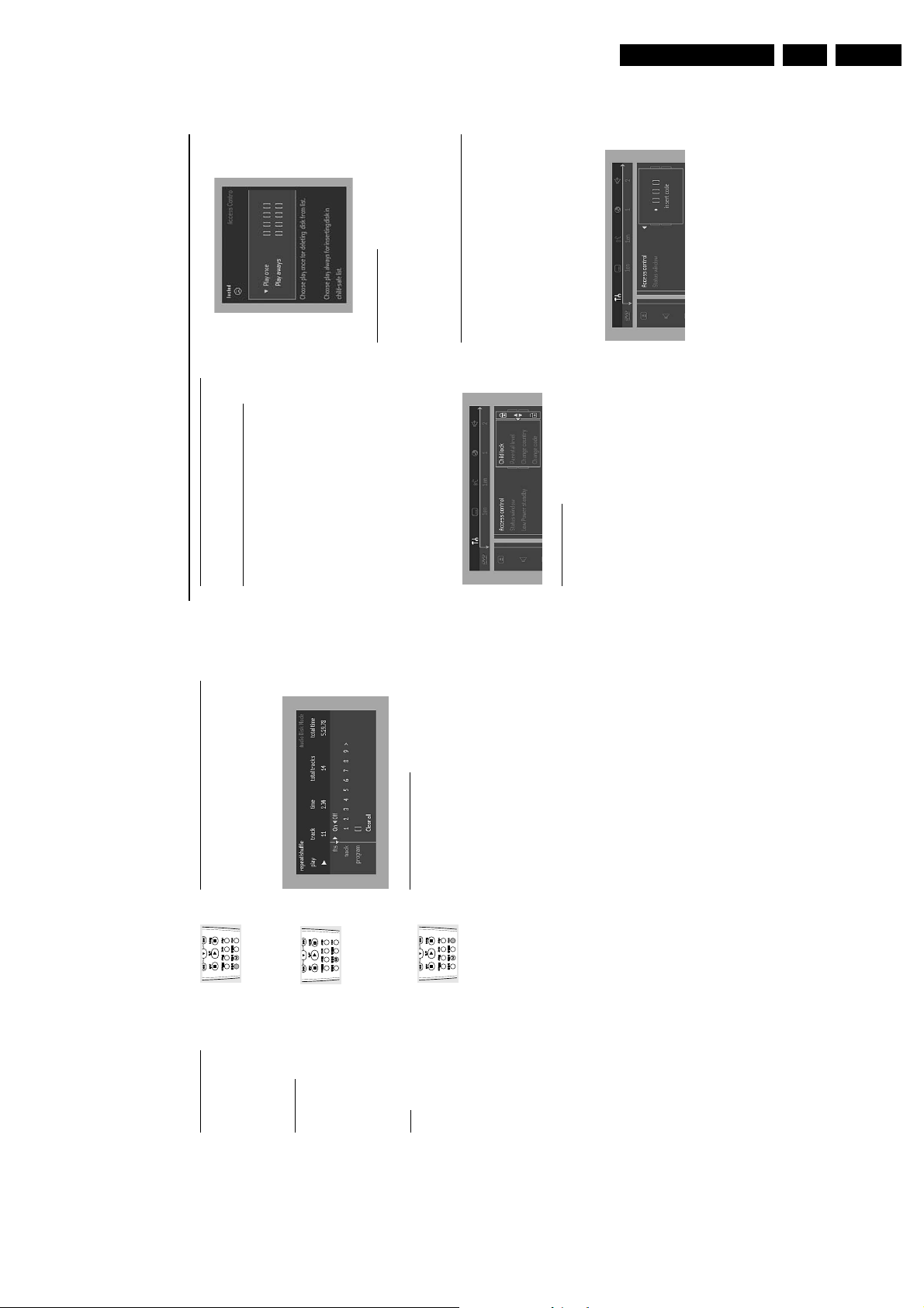
When disc playback is stopped, select ACCESS
CONTROL in the features menu using the 3/4 keys.2Enter a 4-digit code of your own choice.3Enter the code a second time.4Move to “CHILD LOCK” using the 3/4 keys.5Move to LOCK/UNLOCK using the 2 key.6Select LOCK using the 3/4 keys.7Press OK or 1 to confirm, then press 1 again to exit the
menu.
➜ Now unauthorized discs will not be played unless the
4-digit code is entered.
8
Select UNLOCK to deactivate the CHILD LOCK.
Note: Confirmation of the 4-digit code is necessary when:
– The code is entered for the very first time (see above),
– The code is changed (see ‘Changing the 4-digit code’),
– The code is cancelled (see ‘Changing the 4-digit code’).
Authorizing discs
¶ Inser t the disc. See ‘Loading disc’.
➜ The ‘child protect’ dialog will appear.
You will be asked to enter your secret code for ‘Playback
Once ‘or ‘Playback Always.’ If you select ‘Playback Once’, the
disc can be played as long as it is in the player and the
player is ON. If you select ‘Playback Always’, the disc will
become child safe (authorized) and can always be played,
even if the Child Lock is set to ON.
Notes:
– The player memory maintains a list of 120 authorized
(‘Child safe’) disc titles. A disc will be placed in the list when
‘Playback Always’ is selected in the ‘child protect’ dialog.
– Each time a ‘c hild safe’ disc is played, it will be placed on
top of the list. When the list is full and a new disc is added, the
last disc in the list will be removed from the list.
– Double-sided DVDs may have a different ID for each side.
In order to make the disc ‘child safe’, each side has to be
authorized.
– Multi-volume VCDs may have a different ID for each
volume. In order to make the complete set ‘child safe’, each
volume has to be authorized.
Deauthorizing discs
¶ Inser t the disc. See ‘Loading disc’.
➜ Playback starts automatically.
¶ Press 9 while { is visible.
➜ The | will appear and the disc is now deauthorized.
Access Control: Parental
Control (DVD-Video only)
Movies on DVDs may contain scenes not suitable for
children. Therefore, discs may contain ‘Parental Control’
information which applies to the complete disc or to
certain scenes on the disc. These scenes are rated from 1
to 8, and alternative, more suitable scenes are available on
the disc. Ratings are country dependent. The ‘Parental
Control’ feature allows you to prevent discs from being
played by your children or to have certain discs played with
alternative scenes.
A
CCESS
C
ONTROL
Access Control
GB 13DVD703 /XX1 3.
Favorite Track Selection (FTS)
Program
for a particular disc in the player memory.
¶ The FTS Program allows you to store your favorite tracks
¶ Each FTS Program can contain 20 tr acks.
appears on the display.
TRK
appears on the display.
REPEAT
REPEAT
¶ To repeat the track currently playing, press
➜
REPEAT.
➜
¶ To repeat the entire disc, press REPEAT a second time.
Repeat track/disc
¶ To exit Repeat mode, press REPEAT a third time.
Repeat A-B
To repeat a sequence:
¶ Press REPEAT A-B at your chosen starting
Storing an FTS Program
Load a disc and stop playback.2Use 4 to go to the list of available tracks.3Use 2 or 1 to select tracks from the list.
1
appears on the display, and the sequence begins to
B
- appears on the player display.
-
A
A
play repeatedly.
➜
point.
➜
¶ Press REPEAT A-B again at your chosen end point.
¶ To exit the sequence, press REPEAT A-B again.
Scan
Scanning plays the first 10 seconds of each
track on the disc.
To go directly to any track, enter the track number using
the numerical keys (0-9).
again or press B.
¶ Press SC AN.
¶ To continue playback at your chosen track, press SC AN
Store each track by pressing OK.
➜ The tr ack numbers will be added to the list.
➜ The number of tr acks and the playing time of the
program will be shown on the screen and the player display.
When your FTS Program is complete, press B to start
playback or, press 3 to go back to Stop mode. In either
4
case, the FTS Program will be automatically memorized.
Switching FTS ON/OFF
Use 3 4 to move to select desired tracks.2Use 2 or 1 to select either ON or OFF.
1
Erasing a track from an FTS Program1Use 4 to go to the list of selected tracks.2Use 2 and 1 to select the track number you wish to erase.3Press OK.
➜ The tr ack number will be erased from the list of selected
tracks.
Erasing the complete program1Use 4 to select CLEAR ALL, then press OK.
➜ The complete FTS Progr am for the disc will be erased.
15
PERATION
O
Page 14

GB 14 DVD703 /XX13.
18
Before Requesting Service
If it appears that the DVD-Video player is faulty, first consult this checklist. Something may have been overlooked. Under no
circumstances should you attempt to repair the system yourself; this will invalidate the warranty.
Look for the specific symptom(s). Then perform only the actions listed to remedy the specific symptom(s).
Symptom Remedy
No power – Make sure the mains cord (AC Power) is properly connected.
– Check if there is power at the AC outlet by plugging in another appliance.
No picture – Check if the TV is switched on.
– Check the video connection.
Distorted picture – Check the disc for fingerprints and clean the disc with a soft cloth, wiping
from the center to the edge in a straight line.
– Sometimes a small amount of picture distortion may appear .This is not a
malfunction.
Completely distorted picture – If the picture is distor ted completely or if the picture rolls vertically,
or no color with player menu make sure the NTSC/PAL setting at the DVD player matches the video
signal of your television.
– If your TV video signal is NTSC , select the NTSC setting at the DVD player.
– If your video signal is PAL, select the PAL setting. - See NTSC/PAL SETTINGS.
Distorted or black/white picture – The disc format does not match your TV’s video signal (PAL/NTSC).
with DVD or Video CD
No sound – Check audio connections.
– If you are using a HiFi amplifier, try another sound source .
Distorted sound from HiFi – Check to make sure that no audio connections are made to the amplifier’s
amplifier phono input.
No audio at digital output – Check the digital connections.
– Check the settings menu to make sure the digital output is set to ALL or
PCM.
– Check if the audio format of the selected audio language matches your
receiver capabilities.
Disc can’t be played – Ensure the disc label is facing up.
– Clean the disc.
– Check if the disc is defective by trying another disc.
– Check to see if the disc is defective, badly scratched or warped (not flat).
No return to start-up screen when – Reset by switching the player off, then on again.
disc is removed – Check to see if the program requires another disc to be loaded.
The player does not respond to – Aim the remote control directly at the sensor on the front of the player.
the remote control – Remove any obstacles between the player and the remote control.
– Inspect or replace the batteries in the remote control.
Buttons do not work – In order to completely reset the player, unplug the AC cord from the AC
outlet. (Please ensure that the set is not in Initial Setup mode)
Player does not respond to some – Operations may not be permitted by the disc. Refer to the instructions of
operating commands during the disc.
playback
DVD-Video player cannot read – Use a commonly available cleaning CD/DVD to clean the lens before
CDs/DVDs sending the DVD-Video player for repair.
B
EFORE
R
EQUESTING
S
ERVICE
Directions for use
Changing the 4-digit code
When disc playback is stopped, select ACCESS
CONTROL in the features menu using the 3/4 keys.2Enter the old code.3Move to CHANGE CODE using the 4 key.4Press the 2 key.5Enter the new 4-digit code.6Enter the code a second time and reconfirm by pressing
OK.7Press 1 to exit the menu.
1
Activating/Deactivating Parental Control
When disc playback is stopped, select ACCESS
CONTROL in the features menu using the 3/4 keys.2Enter your 4-digit code. If necessary, enter the code a
second time.3Move to Parental Control using the 3/4 keys.4Move to VALUE ADJUSTMENT (1-8) using the 2 key.5Then use the 3/4 keys or the numerical keys on the
remote control to select a rating from 1 to 8 for the disc
1
If you forget your 4 digit code
inserted.
Rating 0 (displayed as ‘– –’):
Parental Control is not activated. The Disc will be played in
Press 9 to exit the ‘Child Protect’ screen.2Select ACCESS CONTROL in the features menu using
1
full.
Ratings 1 to 8:
The disc contains scenes not suitable for children. If you set
the 3/4 keys.3The 4-digit code can be cancelled by pressing 9 four times
in the ‘Access Control’ dialog.4You can then enter a new code (twice!) as descr ibed above
(Changing the 4 digit code).
a rating for the player, all scenes with the same rating or
lower will be played. Higher r ated scenes will not be played
unless an alternative is available on the disc. The alternative
must have the same rating or a lower one. If no suitable
alternative is found, playback will stop and the 4-digit code
has to be entered.
Parental Control Disclaimer
This DVD player features the PARENTAL CONTROL
system which is intended to activate when playing DVD
discs furnished with certain software coding. This is
according to technical standards adopted by the set maker
Press OK or 1 to confirm, then press 1 again to exit the
menu.
6
and disc content industries.
Please note that the PARENTAL CONTROL system
will not operate a DVD disc which is not furnished with the
appropriate software coding. Also note that at the time of
release of this DVD player, certain aspects of the technical
standards had not been settled between set makers and
the disc industries.
On this basis, Philips cannot guarantee the functioning of
the PARENTAL CONTROL system and denies any
Country
liability associated with unintended watching of disc
content.
If in doubt, please make sure the disc plays according to
your PARENTAL CONTROL settings before you allow
children access to the player.
When disc playback is stopped, select ACCESS
CONTROL in the features menu using the 3/4 keys.2Enter the 4-digit code.3Move to CHANGE COUNTRY using the 4 key.4Press the 2 key.5Select a country using 3/4.6Press OK or 1 to confirm, then press 1 again to exit the
menu.
1
17
ONTROL
C
CCESS
A
Page 15

4. Mechanical instructions
4.1 Dismantling instructions
(board to frame)
226 (board to frame)
-> Remove 2 screws 222
-> Release snaps of 2 spacer
-> Demount board
(skt cinch to back-plate)
and screw 228 ( S-video
to back-plate )
-> Remove screws 227
221
-> Release snaps of 2 spacers
-> Demount board
Mounting
Demounting
Power supply unit 1005
-> Remove connections
A/V board 1002
-> Remove connections
Mechanical instructions
GB 15DVD703 /XX1 4.
130201
CL 16532007_057.eps
Cover 232
-> Remove 7 screws 233
-> Lift cover at rearside to
Remove 4 screws to remove loader.
DVD module
turntable motor and sledge
motor
(mono-board to VAL6011)
connection to OPU and wire
remove
Mono-board
DVD module 218
Front assy 200
( See instruction below )
-> Remove connections to
-> Open Tray
( front to frame )
-> Remove 2 screws 212
-> Unlock front from frame by
(module to frame)
-> Remove 4 screws 217
-> Demount module
releasing successively 6
snaps ( 2 each on the side,
top and bottom )
the set ( service position )
-> Place front assy in front of
DVD Mono board
-> See also exploded view of
-> Remove flex connections to
-> Remove 4 screws 10 to 13
Standby board and switch
assy 1003B
-> Remove 2 screws 211
-> Demount board
by pulling it forward
Headphone board 1006
-> Remove connections
-> Remove 3 knobs 208
-> Remove carefully flex
(board to front) ,pay
-> Remove 3 screws 209
to the tray motor
-> Demount the board
attention to earth spring
252
-> Demount board
When a disc is loaded, unlock the tray by pushing the slide inwards by way
of a screwdriver and pull tray outwards.
DISMANTLING INSTRUCTIONS DVD703/XX1
See exploded view for item numbers and diversity table for items used
Display board 1003A
-> Remove connections
(board to front) ,pay attention
-> Remove 7 screws 211
to earth spring 250
-> Demount board
Manually opening of tray
When it is not possible to open the tray with the open/close button,
the tray can manually be opened.
When no disc is loaded, unlock the tray by moving the slide from the left
to the right and pull tray outwards.
Page 16

GB 16 DVD703 /XX14.
4.2 Exploded views
Mechanical instructions
020201
CL 16532007_029.eps
Page 17

Mechanical instructions
GB 17DVD703 /XX1 4.
140201
CL 16532007_031.eps
Page 18

GB 18 DVD703 /XX14.
Mechanical instructions
CL06532147_001.eps
151100
Page 19
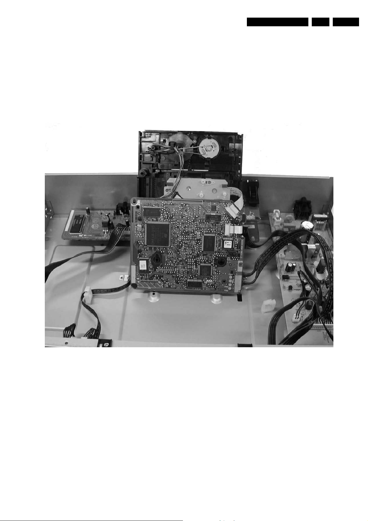
4.3 Service position
See figure 4-1 for the service position
1. Remove the cables from the cable tie housing.
2. Remove 4 screws that mount the DVD module to the
bottom frame.
3. Move the DVD module backward slightly and flip the
module over, so that the component side of the
board faces upwards, and the module is in the
service position.
Mechanical instructions
GB 19DVD703 /XX1 4.
Figure 4-1
Page 20
GB 20 DVD703 /XX15.
Diagnostic software descriptions and troubleshooting
5. Diagnostic software descriptions and troubleshooting
5.1 Dealerscript
5.1.1 Purpose of Dealer Script
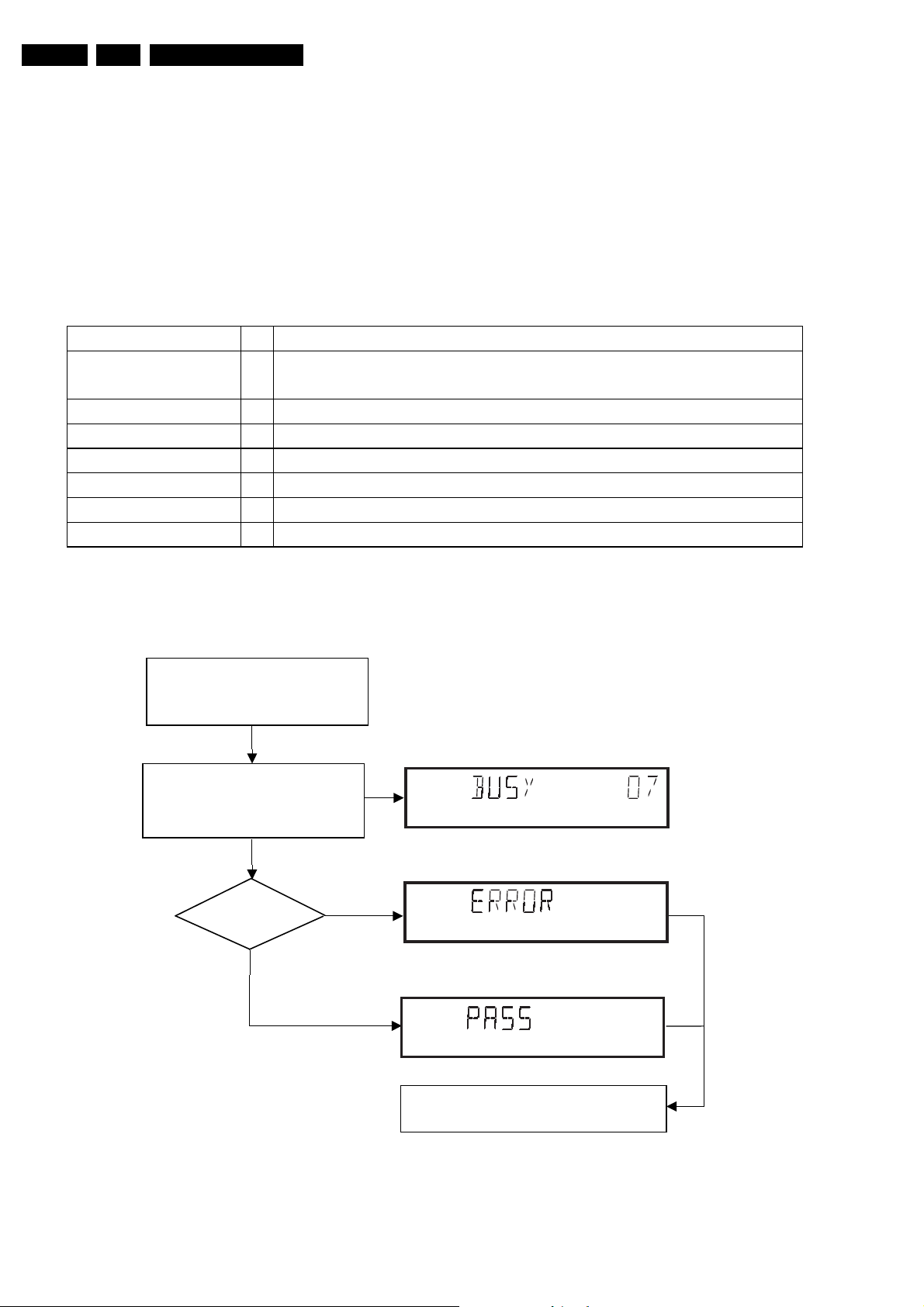
The dealer script can give a diagnosis on a standalone DVD
player; no other equipment is needed to perform a number of
hardware tests to check if the DVD player is faulty. The
diagnosis is simply a "error" or "pass" message; no indication
is given of faulty hardware modules. Only tests within the
scope of the diagnostic software will be executed hence only
faults within this scope can be detected.
Nucleus Description
VideoColSetupComm
Checks the I2C interface with the RGB video processor on the Audio/Video
7
board (only for DVD players with RGB video processor).
PapChksFl
PapI2cDisp
PapS2bEcho
PapI2cNvram
PapNvramWrR
CompSdramWrR
Calculate and verify checksum of FLASH memory.
6
Checks the I2C interface with the slave processor on the display PCB.
5
Checks the I2C interface to the basic engine.
4
Checks the I2C interface with the NVRAM.
3
Pattern test of all locations in the NVRAM
2
Pattern test of all locations in the SDRAM(s).
1
5.1.2 Contents of Dealer Script
The dealer script executes all diagnostic nuclei that do not
need any user interaction and are meaningful on a
standalone DVD player.
The nuclei called in the dealer script are the following (the
number after each nucleus name corresponds with the
number being on the local display when the nucleus is
executed during the dealer script):
CL06532096_001.eps
050700
Press 2 keys simultaneously
<OPEN/CLOSE> + <PAUSE>
Connect to mains.
During the test, the following display
is shown: the counter counts down
from the number of nuclei to be run
before the test finishes. Example:
SET O.K.?
YES
NO
Figure 5-1
To exit DEALER SCRIPT ,disconnect from mains.
Figure 5-2
CL 96532065_004.eps
120799
Page 21
Diagnostic software descriptions and troubleshooting
s
GB 21DVD703 /XX1 5.
5.2 PLAYER SCRIPT
5.2.1 Purpose of Player Script
The Player script will give the opportunity to perform a test
that will determine which of the DVD player's modules are
faulty, to read the error log and error bits and to perform an
endurance loop test. To successfully perform the tests, the
DVD player must be connected to a tv set to check the output
of a number of nuclei. For DVDv2b a multi-channel amplifier,
a set of 6 boxes and an external video source are necessary
to test. To be able to check results of certain nuclei, the
player script expects some interaction of the user (i.e. to
approve a test picture or a test sound). Some nuclei (e.g.
nuclei that test functionality of the Basic Engine module)
require that the DVD player itself is opened, to enable the
user to observe moving parts and approve their movement
visually. Only tests within the scope of the diagnostic
software will be executed hence only faults within this scope
can be detected.
5.2.2 Contents of Player Script
The player script contains all nuclei that are useful on a DVD
player that is connected to a tv-set and help to determine
which module of the DVD player is faulty, as well as to read
out the contents of the error logs.
5.2.3 Structure of Player Script
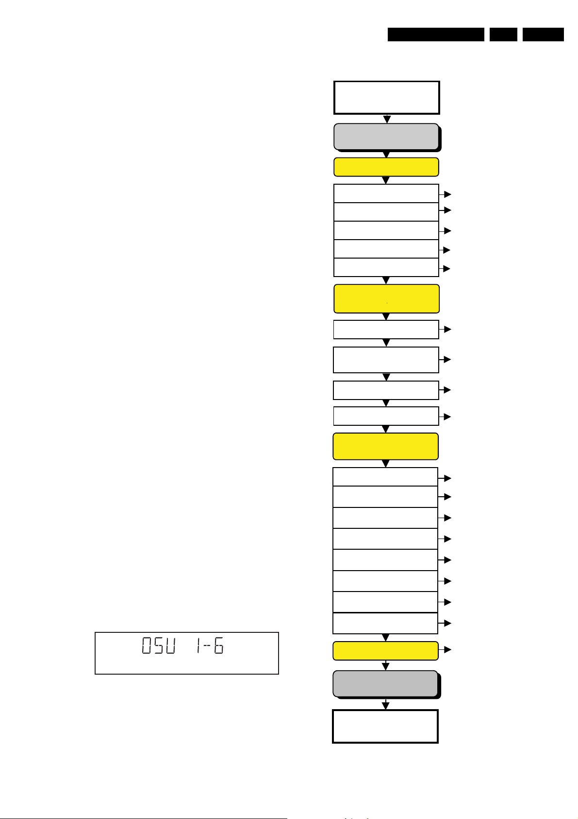
The player script consists of a set of nuclei testing the three
hardware modules in the DVD player: the Display PWB, the
Digital PWB and the Basic Engine.
Nuclei run by the player test need some user interaction; in
the next paragraph this interaction is described. The player
test is done in two phases:
1. Interactive tests: this part of the player test depends
strongly on user interaction and input to determine
nucleus results and to progress through the full test.
Reading the error log and error bits information can be
useful to determine any errors that occurred recently
during normal operation of the DVD player.
2. The loop test will loop through the list of nuclei
indefinitely, till the NEXT key is pressed. The list of nuclei
is as follows:
• VideoColSetupComm
• VideoScartSwComm
• PapChksFlash
• PapI2cNvram
• CompSdramWrR
• PapS2bEcho
• PapI2cDisp
For DSW version 1.6 and above. the DSW version number
will be displayed on the local display. Press NEXT to
continue to the display test.
The display should look like the following:
5.2.4 Survey
Press 2 keys simultaneously
<OPEN/CLOSE> + <STOP>
Connect to main
INTERACTIVE TESTS
DISPLAY PCB
DISPLAY TEST
LED TEST
KEYBOARD TEST
REMOTE CONTROL
P50 LOOP BACK TEST
MONO PCB
DIGITAL PART
PICTURE TEST
SOUND 1 TEST
SCART DVD TEST
SCART LOOP TEST
SOUND 2 TEST
MONO PCB(SERVO)
& BASIC ENGINE
VERSION NUMBER
TRAY TEST
SLEDGE TEST
DISC MOTOR TEST
FOCUS TEST
RADIAL TEST
JUMP TEST
TRAY TEST
DispDisplay(30)
DispLed(29)
DispKeyb(27)
DispRc(28)
DispP50(60)
VideoColDencOn(23a)
AudioPinkNoiseOn(20a)
VideoScartSwDvd(54a)
VideoScartSwPass(54b)
AudioSineOn(21a)
BeVer(37)
BeTrayOut/In(43ab)
BeSledgeOut/In(41ab)
BeDiscMotorOn(39a)
BeFocusOn(38a)
BeRadialOn(40a)
BeGroovesIn/Mid/Out(42abc)
BeTrayOut/In(43ab)
ERROR LOG & BITS
CL 16532007_002.eps
010201
Figure 5-3
LOOP TEST
To exit player test,
disconnect from mains
Figure 5-4
LogReadErr(31)
LogReadbits(32)
= Dealer script exclusive of test2
CL 16532007_003.eps
300101
Page 22
GB 22 DVD703 /XX15.
5.3 DISPLAY PCB
5.3.1 DISPLAY TEST
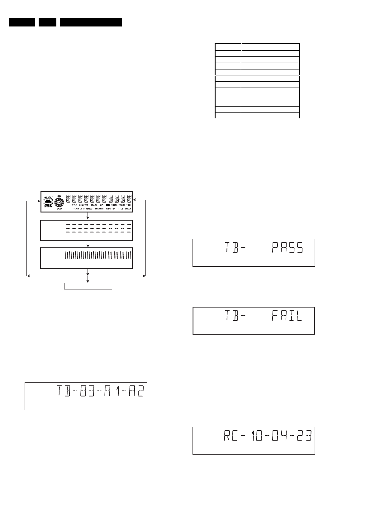
The display test is performed by nucleus DispDisplay. By
putting a series of test patterns on the local display, the local
display is tested. To step through all different patterns, the
user must either press PLAY (pattern is ok) or PAUSE
(pattern was incorrect) to proceed to the next pattern. The
display of patterns is continued in a cyclic manner until the
user presses NEXT. If the user presses NEXT before all
display patterns are tested, the DispDisplay nucleus will
return TRUE (display test successful).
5.3.2 LED TEST
Diagnostic software descriptions and troubleshooting
key id. key
0PLAY
1NEXT
2 PREVIOUS
3 PAUSE
4STOP
5 OPEN/CLOSE
6 3D-SURROUND
7 KEY- (Mic Control)
8 Once More (Mic Control)
9 KEY+(Mic Control)
A STAND BY
CL16532007_007.eps
300101
The LED(s) on the DVD player is (are) tested by nucleus
DispLed. The user must check if the LED(s) is (are) lighted;
if it is, press PLAY, if it is not, press PAUSE. By pressing
NEXT the script will proceed to the next test. If the user
presses NEXT before PLAY or PAUSE, the DispLed nucleus
will return TRUE (LED test successful).
If OK, press PLAY If NOK, press PAUSE
If OK, press PLAY If NOK, press PAUSE
If OK, press PLAY If NOK, press PAUSE
press NEXT to continue
CL 96532065_006.eps
120799
Figure 5-5
Figure 5-7
If any keys are detected more than once (due to hardware
error), the key-code is displayed twice (or more), with the
second digit increased by 1.
If the user does not press all keys minimally once (in any
order), the DispKeys nucleus will return FALSE and cause an
error in the overall result of the player script.
The test will also pass if all buttons, except the microphone
key buttons, are pressed.
The user can leave the keyboard test by pressing the NEXT
key on the local display of the DVD player for at least one full
second.
The result of the keyboard test is shown on local display as
follows:
CL 96532065_009.eps
120799
Figure 5-8
Or
5.3.3 KEYBOARD TEST
The keyboard of the DVD player is tested by nucleus
DispKeyb. The user is expected to press all keys on the local
keyboard once. The code of the key pressed is shown on the
local display (1 hexadecimal digit) immediately followed by a
(hexadecimal) number indicating how many times that key
has been pressed. Example of the local display during this
test:
Figure 5-6
The key-codes displayed on the local display will scroll from
right to left when the display gets full, the text "tb-" will remain
on display.
CL 96532065_007.eps
120799
Figure 5-9
Pressing NEXT on the local keyboard again will proceed to
the next text.
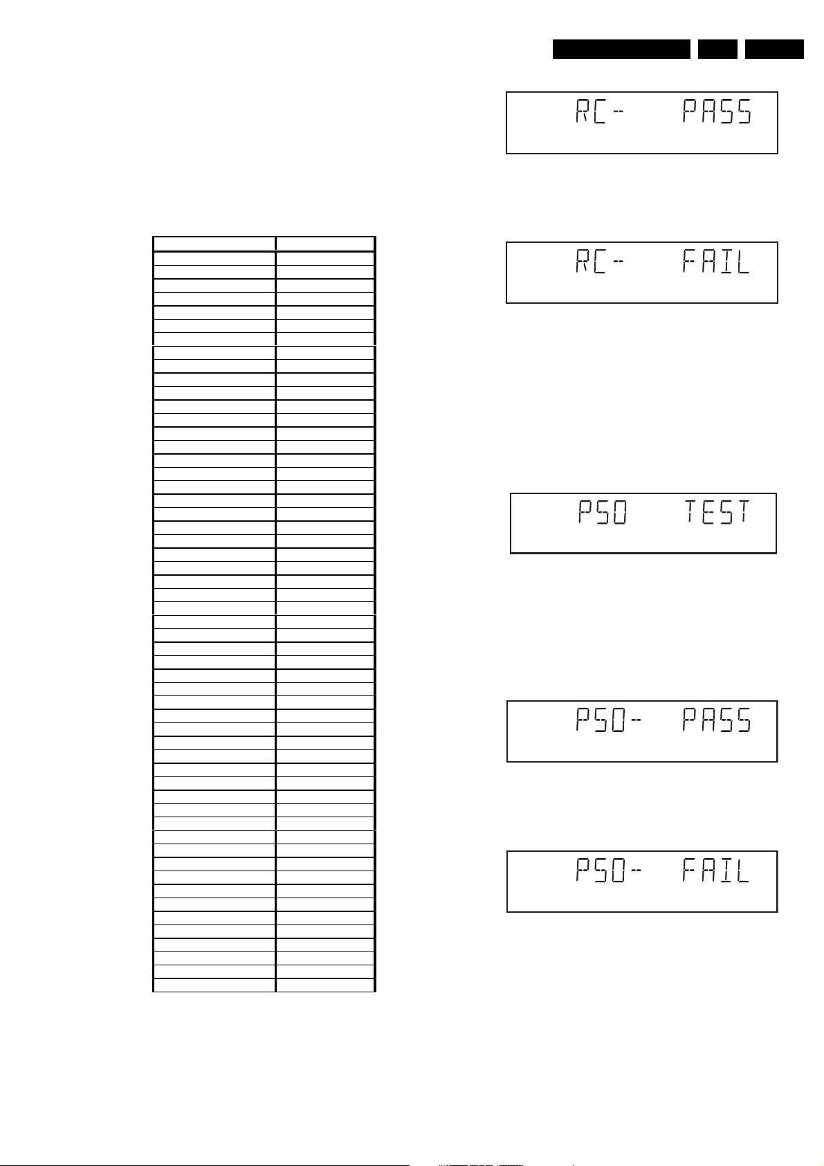
5.3.4 REMOTE CONTROL TEST
The remote control of the DVD player is tested by nucleus
DispRc. The user must press any key on the remote control
just once. The codes of the key pressed will be shown on the
local display in hexadecimal format. Example:
Figure 5-10
In this example 23 is the hexidecimal code of the pressed RC
key. The user can leave the remote-control test by pressing
NEXT on the local keyboard of the DVD player. The remote
CL 96532065_010.eps
120799
CL 96532065_011.eps
120799
Page 23
Diagnostic software descriptions and troubleshooting
control test is successful if a code was received before the
user pressed the NEXT key; pressing the NEXT key before
pressing a key on the remote control gives an error in the
remote control test (note that the remote control test will also
fail if a key on the remote control was pressed but no code
was received). The remote control test does not check upon
the contents of the received code, that is it will not be
checked if the received code matches the key pressed. If
desired, the user can manually check this code by using a
code-table for the remote control key-codes.
C Key id Hexadecimal code
STANDBY 0C
STOP 31
PLAY
PLAY BACKWARD 2D
PAUSE 30
STEP FORWARD F6
STEP BACKWARD F5
FORWARD 28
FORWARD 4X DF
FORWARD 8X E0
BACKWARD 29
BACKWARD 4X DE
BACKWARD 8X DD
SLOW 22
SLOW 2 D9
SLOW BACKWARD 23
SLOW BACKWARD 2 DA
NEXT 20
PREVIOUS 21
CURSOR UP 58
CURSOR DOWN 59
CURSOR LEFT 5A
CURSOR RIGHT 5B
OK 5C
0 0
1 1
2 2
3 3
4 4
5 5
6 6
7 7
8 8
9 9
TOGGLE C8
ANGLE 85
AUDIO 4E
SUBTITLES 4B
SUBTITLE ON/OFF E3
ROOT MENU 54
TITLE MENU 71
MENU D1
SETUP MENU 82
OSD ON/OFF F
RETURN 83
RESUME D7
SCAN 2A
SHUFFLE 1C
REPEAT 1D
A/B REPEAT 3B
TOGGLE SCART 43
OPEN/CLOSE 42
FTS FB
KARAOKE E4
OPTION FA
Figure 5-11
After pressing NEXT, the result of the remote control test is
displayed on the local display of the DVD player as follows:
2C
CL06532096_003.eps
050700
Figure 5-12
Or
Figure 5-13
Pressing NEXT on the local keyboard again will proceed to
the next test.
5.3.5 P50 LOOP-BACK TEST
For the P50 loop-back test, the user must first press a key to
decide if the test is to be performed.
The display will show the following message:
Figure 5-14
If the user presses PAUSE, the P50 test will be skipped.
If the user presses PLAY, the P50 test is performed and the
result is displayed as follows:
Test successfull:
Figure 5-15
Test fails:
Figure 5-16
Press the NEXT key to continue to the next text
5.4 MONO PCB DIGITAL PART
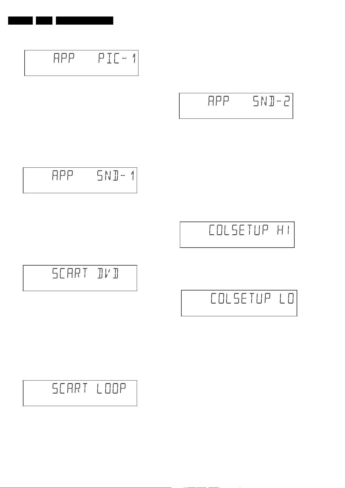
5.4.1 PICTURE TEST
The picture test is performed by putting a predefined picture
(colour bar) on the display (nucleus VideoColDencOn) and
GB 23DVD703 /XX1 5.
CL 96532065_013.eps
120799
CL 96532065_014.eps
120799
CL 16532007_004.eps
010201
CL 16532007_005.eps
010201
CL 16532007_006.eps
010201
Page 24
GB 24 DVD703 /XX15.
Diagnostic software descriptions and troubleshooting
asking the user for confirmation. The display will show the
following message:
Figure 5-17
By pressing PLAY the user confirms the test, pressing
PAUSE will indicate the picture was invisible or incorrect.
Pressing NEXT will proceed to the next test
5.4.2 SOUND 1 & SCART DVD TEST
The first soundtest is performed by starting a pink noise
sound that needs confirmation from the user (nucleus
AudioPinkNoiseOn); the display will show the following
message very shortly:
Figure 5-18
This sound will only be audible from version cut3.1 of
Sti5505(item7503 on mono board) onwards. After starting up
sound 1, SCART loop-trough will be simultaneously active
during this test. SCART loop-trough will be measured with
the aid of an external video source.
When entering the SCART loop-trough, the local display
indicates:
CL 96532065_015.eps
120799
CL 96532065_016.eps
120799
The test can be left by pressing the NEXT key for more than
one second.
5.4.3 SOUND 2 TEST
The second soundtest is performed by producing a sine
sound (nucleus AudioSineOn). The signal can be stopped by
pressing the STOP-key. The display will show the following
message:
Figure 5-21
By pressing PLAY the user confirms the test, pressing
PAUSE will indicate that something went wrong. Pressing
NEXT will proceed to the next; if the user presses NEXT
without pressing PLAY or PAUSE first, the result of this test
will be TRUE (sound ok).
5.4.4 Colour setup test
The colour setup test is performed by putting the internally
generated colour bar in different settings on the TV screen.
The first colour bar will be displayed in setting 1. the display
will show the following message:
Figure 5-22
CL 96532065_019.eps
120799
CL06532096_004.eps
050700
CL 96532065_017.eps
120799
Figure 5-19
On the TV screen a colour bar (generated by nucleus
VideoColDencOn) is visual and the internally generated
pinknoise is audible. By pressing PLAY the user confirms the
test, pressing PAUSE will indicate the sound was inaudible or
incorrect. Pressing NEXT will proceed to the next test; if the
user presses NEXT without pressing PLAY or PAUSE first,
the result of this test will be TRUE (sound ok). By pressing
the NEXT button there will be switched over to the external
source, this must become now visible on the TV screen
(using the SCART). The local display indicates:
CL 96532065_018.eps
120799
Figure 5-20
The internally generated colour bar is still available on the
CVBS and Y/C outputs. And the pinknoise-signal is still
available on the cinch audio outputs. By pressing the PREV
button, the internal generated colour bar becomes visual
again.
By pressing the NEXT button, you can go to the second
setting. The local display indicates:
Figure 5-23
By pressing the PREVIOUS button, the colour bar with the
first setting becomes visual again.
By pressing PLAY the user confirms the test, pressing
PAUSE will indicate that something went wrong.
The test can be left by pressing the NEXT key for more than
one second; if the user presses NEXT without pressing PLAY
or PAUSE first, the result of the test will be TRUE )colour setup ok).
5.5 BASIC ENGINE
5.5.1 VERSION NUMBER
In the basic engine tests, the version number of the Basic
Engine will be shown first, as the following example:
CL06532096_005.eps
050700
Page 25
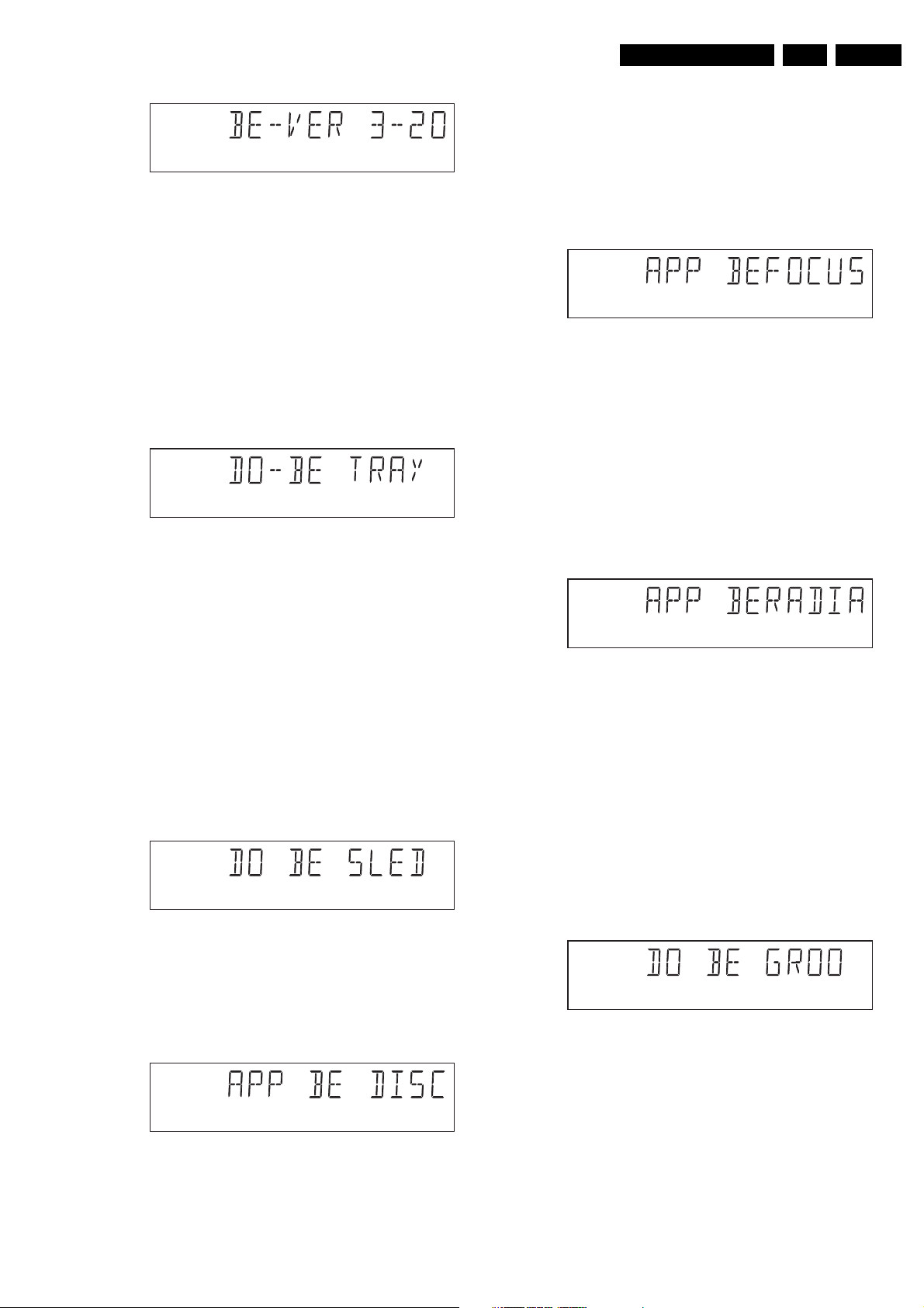
Diagnostic software descriptions and troubleshooting
Figure 5-24
By pressing the NEXT key, the Basic Engine tests are
started.
5.5.2 TRAY TEST
First, the tray is tested. The purpose of this test is also to give
the user the opportunity to put a disc in the tray of the DVD
player. Some tests on the Basic Engine require that a
disc(e.g. DVD MPTD test disc) is present in the player. At the
end of the Basic Engine tests this tray test will be repeated
solely to enable the user to remove the disc in the tray. The
local display will look as follows:
Figure 5-25
CL 96532065_020.eps
120799
CL 96532065_021.eps
120799
of the disc motor (nucleus BeDiscMotorOff). If the user
presses NEXT before pressing PLAY or PAUSE, the result of
this test will be TRUE (disc motor is running).
5.5.5 FOCUS TEST(visual test)
The fourth Basic Engine test tests the focussing; first
focussing is turned on by calling nucleus BeFocusOn. The
display will look as follows:
Figure 5-28
By pressing PLAY the user confirms that the focussing was
succesful; pressing PAUSE indicates a focussing failure.
Pressing NEXT proceeds to the next test after a reset of the
focussing (nucleus BeFocusOff); if NEXT is pressed before
PLAY or PAUSE, the result of this test will be TRUE (focus
successful).
5.5.6 RADIAL TEST(visual & listening test)
The fifth Basic Engine test tests the radial functionality
(nucleus BeRadialOn); the local display looks as follows:
GB 25DVD703 /XX1 5.
CL 96532065_024.eps
120799
By pressing PLAY or PAUSE the user can toggle the position
of the tray. Note that this test will not contribute to the test
result of the Basic Engine. Pressing NEXT will proceed to the
next test, after the tray has been closed (by the software) if it
was open.
5.5.3 SLEDGE TEST(visual test)
The second Basic Engine test tests the sledge; the user can
move the sledge as many times as desired by using PLAY
(nucleus BeSledgeOut) and PAUSE (nucleus BeSledgeIn).
Pressing NEXT on the local keyboard proceeds to the next
test. Note that this test will not contribute to the test result of
the Basic Engine. The local display will look as follows during
the sledge test:
Figure 5-26
5.5.4 DISC MOTOR TEST(visual test)
The third Basic Engine test tests the disc motor (nucleus
BeDiscMotorOn); the local display looks as follows:
CL 96532065_022.eps
120799
Figure 5-29
By pressing PLAY the user confirms that the radial function
worked; pressing PAUSE indicates the function does not
work. Pressing NEXT proceeds to the next test, after a reset
of the radial (nucleus BeRadialOff). If the user presses NEXT
before pressing PLAY or PAUSE, the result of this test will be
TRUE (radial successful).
5.5.7 JUMP TEST(listening test)
The sixth and last Basic Engine test tests the jumping by
calling nuclei BeGroovesIn, BeGroovesMid and
BeGroovesOut. During this test, the local display looks as
follows:
Figure 5-30
CL 96532065_025.eps
120799
CL 96532065_026.eps
120799
CL 96532065_023.eps
120799
Figure 5-27
By pressing PLAY the user confirms that the disc motor is
running; pressing PAUSE indicates the disc motor does not
work. Pressing NEXT proceeds to the next test, after a reset
The user can switch between the three different types of
groove settings by pressing PLAY (forward to next nucleus in
the list In-Mid-Out) or PAUSE (backward in the list In-MidOut). This is done in a cyclic manner; note that this test will
not contribute to the test result of the Basic Engine. Pressing
NEXT proceeds to the next test, after the disc motor has
been shut off with a call to nucleus BeDiscMotorOff.
Page 26
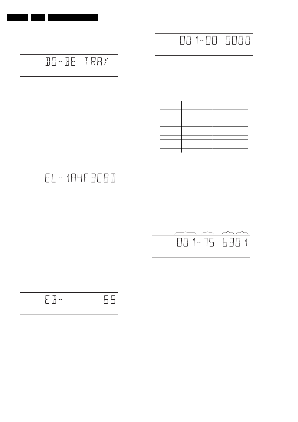
GB 26 DVD703 /XX15.
5.5.8 TRAY TEST
As a last action for the Basic Engine tests, the tray test is
repeated. The local display will look as follows:
Diagnostic software descriptions and troubleshooting
Figure 5-34
CL 96532065_030.eps
120799
Figure 5-31
This test is meant to give the user the opportunity to remove
the disc in the tray. The tray position can be toggled using the
PLAY and PAUSE key. The tray will be closed (by the
software, if it is open) before proceeding to the next test when
the user presses the NEXT key.
5.5.9 ERROR LOG (see table on page 30)
Reading the error log and error bits information can be useful
to determine any errors that occurred recently during normal
operation of the DVD player. Reading the error log is done by
nucleus LogReadErr. The display during the errorlog readout
looks as follows :
Figure 5-32
By pressing PLAY or PAUSE the user can move forward or
backward (respectively) through the logged error codes. The
highlighted number indicates which errorcode is currently on
display (in the example above, errorcode number 4 is
displayed). If "0000" is displayed at all positions, the error log
is empty. Display of the logged errors is done in a cyclic
manner. The errorcode with the lowest highlighted number is
the most recent. By pressing NEXT on the local keyboard,
the user can proceed to the next test.
5.5.10 ERROR BITS (see table on page 30)
Reading the error bits is done by nucleus LogReadBits. The
display during the errorbits readout looks as follows:
CL 96532065_027.eps
120799
CL 96532065_028.eps
120799
CL 96532065_029.eps
120799
The left side of the display contains a 3-digit code, which can
have a value between 000 and 111. These values are to be
interpreted as follows:
Displayed
Value
000 ok ok ok
001 ok ok faulty
010 ok faulty ok
011 ok faulty faulty
100 faulty ok ok
101 faulty ok faulty
110 faulty faulty ok
111 faulty faulty faulty
Indication for each module
Basic Engine Mono
PCB
Display
PCB
CL 96532065_031.eps
120799
Figure 5-35
The loop test will perform the same nuclei as the dealer test,
but it will loop through the list of nuclei indefinitely. The
display of the DVD player will display not only the three digits
indicating correct/faulty modules and the last found error
code (as mentioned, faults are detected as far as they can be
within the scope of the diagnostic software), but also a loop
counter indicating how many times the loop has been gone
through. Example:
FAU LTY
MODULE(S)
LOOP
COUNTER NUCLEUS ERROR
CL 96532065_032.eps
120799
Figure 5-36
The number after the hyphen indicates the number of times
the loop test has been performed; the 4 digits at the right side
of the display show the last error that was found when
running the loop test: the leftmost two digits of this code
indicate which nucleus resulted in a fault; the rightmost two
digits refer to the faultcode within that nucleus. For further
explanation of this error code, see list of error codes below.
Figure 5-33
Only the set errorbits will be shown by their (decimal)
number. Refer to the appropriate documentation for the
explanation of each bit number. If the display only shows
"EB-0", no error bits were set. By pressing NEXT the user
can continue to the next test.
5.6 LOOP TEST (see table below)
At the start of the loop test, the display will show the result of
the interactive player test:
Page 27
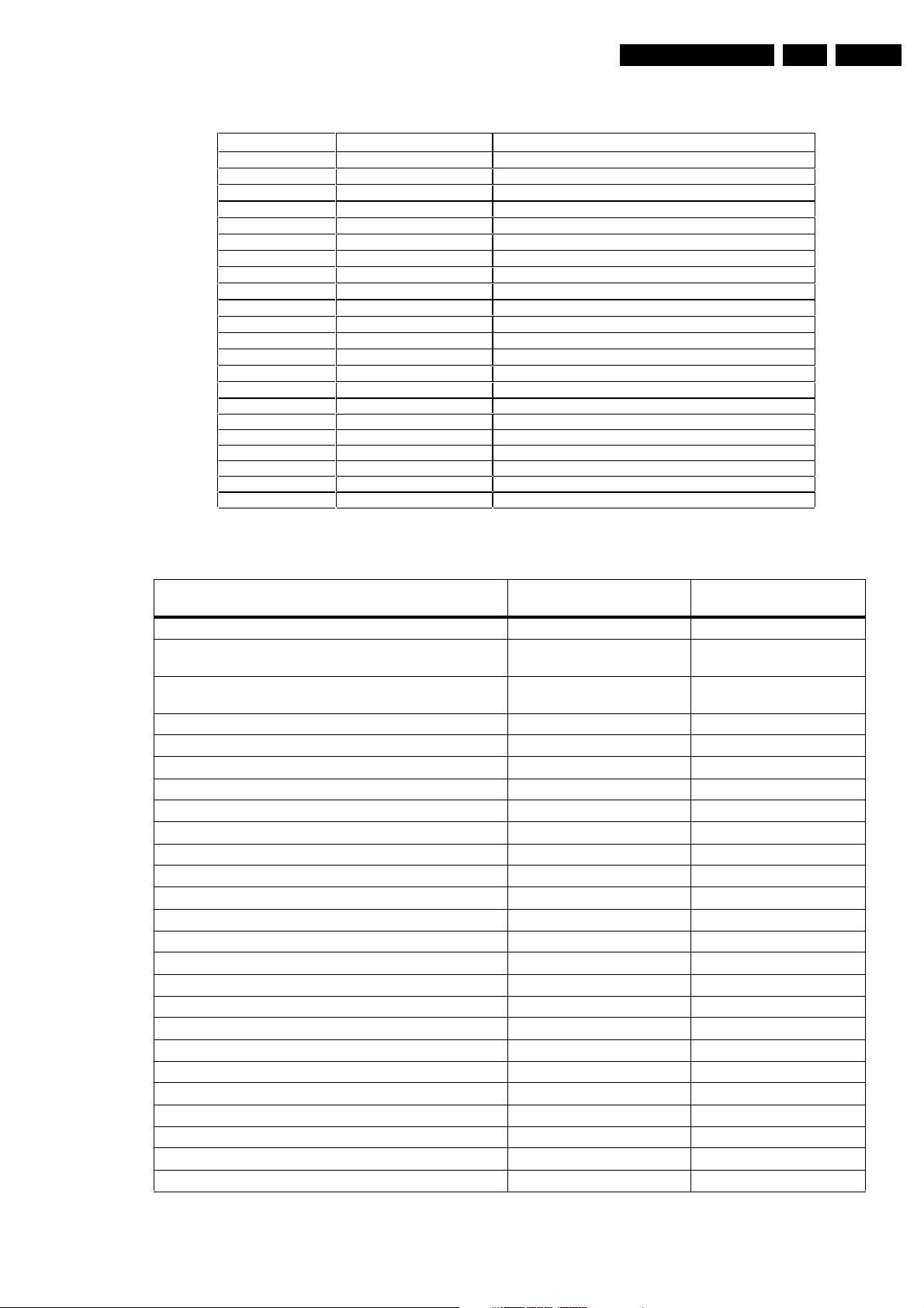
Diagnostic software descriptions and troubleshooting
ERROR CODES LOOP TEST
ERROR CODE NUCLEUS NUMBER ERROR DESCRIPTION
0601
1101
1102
1103
1104
1201
1202
1203
1204
1301
1302
1303
1304
1601
5201
5202
5203
5204
5401
5402
5403
5403
6 Calculated checksum of FLASH is not correct
11 I2C bus busy before start
NVRAM access time-out
No NVRAM Acknowledge
NVRAM reply time-out
12 I2C bus busy
I2C bus not working
Slave controller not responding
Slave response is not correct
13 Parity error from basic engine to serial
Parity error from serial to basic engine
No communication between serial and basic engine
Communication time-out error
16 The SDRAM is faulty
52
I2C bus busy
Error sending I2C command to COLOR SETUP IC
Colour setup IC not responding
Colour setup IC response is not correct
54
I2C bus busy
Error sending I2C command to SCART SWITCH IC
SCART Switch is not responding
SCART Switch response is not correct
CL06532096_006.eps
050700
GB 27DVD703 /XX1 5.
Figure 5-37
Error log / bits table
Basic engine errors Value: Value:
Command to the Basic Engine not allowed in this state or
unknown command
Parameter(s) from the command to the Basic Engine is not
valid
Sledge could not be moved to the inner home position 150103 6
Focus failure 150104 5
Turntable motor speed could not be reached within timeout 150105 4
Radial servo could not get on track on the disc 150106 3
PLL could not lock in the accessing or tracking state 150107 2
Subcode or sector information could not be read 150108 1
requested subcode could not be found 150109 16
Tray could not be closed or opened completely 15010A 15
TOC could not be read within timeout 15010B 14
The requested seek on the disc could not be executed 15010C 13
A requested lead-in is not on the disc 15010D 12
A non existing burst cutting area is requested 15010E 11
S2b communication error 1501F0 10
S2b communication error 1501F1 9
S2b communication error 1501F3 24
S2b communication error 1501F4 23
S2b communication error 1501F5 22
Digital PWB errors
Communication error with the Sti 5505 90000 32
Communication error with the Sti 5505 90001 31
Disply processor errors
Communication error with the display processor 190000 40
Read ERROR LOG in player
script
150101 8
150102 7
Read ERROR BITS in
player script
Page 28
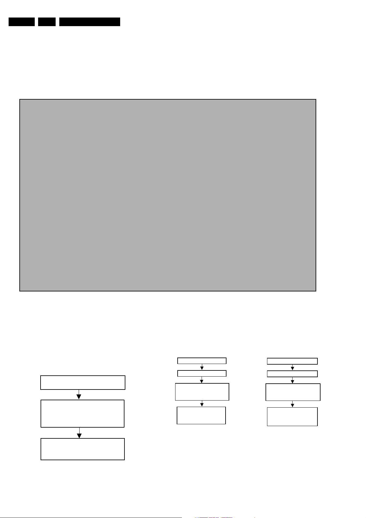
GB 28 DVD703 /XX15.
5.6.1 Servicing DVD loader
The DVD Loader / mechanism, VAL6011, has to be
exchanged completely in case of failure. A new mechanism
can be ordered with codenumber 9305 023 61101.
5.6.2 Reprogramming of new mono boards.
Caution
This information is confidential and may not be distributed. Only a qualified service person should
reprogram the mono board
.
After reset of NV-memory or repair of the mono board, all the customer settings and also the region code
will be lost.
Reprogramming of the mono board will put the player back in the state in which it has left the factory,
i.e. with the default settings and the allowed region code.
Reprogramming is limited to 25 times
When the counter reaches 25, reprogramming is not possible anymore
Reprogramming will be done by way of the remote control.
Put the player in stop mode, no disc loaded.
Press the following keys on the remote control:
PLAY
<
The display shows: “
> followed by numerical keys
- - - - - - - - - - -
Press now successively the following keys :
Diagnostic software descriptions and troubleshooting
<1> <5> <9>
”
for DVD703 /031:
for DVD703 /691:
for DVD703 /751:
for DVD703 /781:
Press <
PLAY
<0><1><3> <0><0><0><0><0><0><0><0><0>
<0><1><0> <0><0><0><0><0><0><0><0><0>
<0><1><2> <0><0><0><0><0><0><0><0><0>
<0><2><1> <0><0><0><0><0><0><0><0><0>
> again.
The TV screen will become BLUE during a short time to confirm that the mono board has been
reprogrammed, then the set goes to standby mode.
5.6.3 Reset of Virgin Mode
After the player has been powered up for test by the dealer,
it would have gone through the Virgin Mode. It is possible to
reset the settings made during that mode before the delivery
of player to the customer. This can be done as shown in the
following diagram:
DISCONNECT FROM MAINS
PRESS 2 KEYS
SIMULTANEOUSLY
<PLAY> + <OPEN/CLOSE>
CONNECT TO MAINS
Figure 5-38
CL 16532007_050.eps
TRADE MODE
When the player is in Trade Mode, the player cannot be
controlled by means of the front key buttons, but only by means
of the remote control.
IF TRADE MODE OFF
DISCONNECT FROM MAINS
PRESS 2 KEYS
SIMULTANEOUSLY
<PREVIOUS> + <OPEN/CLOSE>
CONNECT TO MAINS
PLAYER IS IN TRADE MODE
WHEN PRESSING FRONT
KEYS, THE PLAYER
DOESN'T RESPOND
IF TRADE MODE ON
DISCONNECT FROM MAINS
PRESS 2 KEYS
SIMULTANEOUSLY
<PREVIOUS> + <OPEN/CLOSE>
CONNECT TO MAINS
PLAYER IS IN NORMAL MODE
WHEN PRESSING FRONT
KEYS, THE PLAYER WILL
RESPOND
C06532096_008.eps
050201
050700
VIRGIN MODE IS RESET
TV SCREEN SHOWS
VIRGIN MODE MENU
CL 96532065_034.eps
Figure 5-39
Figure 5-40
070700
Page 29
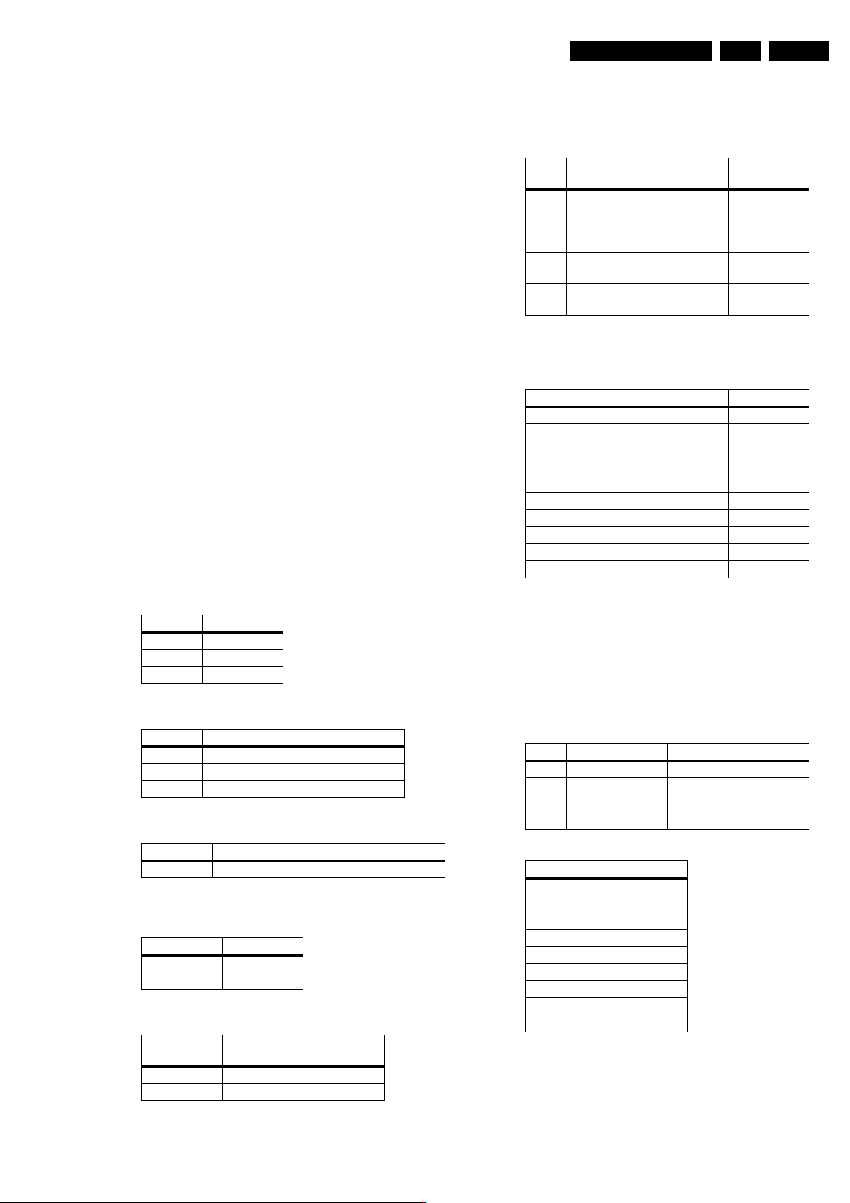
Diagnostic software descriptions and troubleshooting
GB 29DVD703 /XX1 5.
5.7 Test Instruction Audio/Video Board
These test instructions can be used for all versions of the A/
V board which has the following outputs:
• Audio L/R
• 5.1 Audio output
• Subwoofer output
• Optical / Coaxial digital output
• CVBS
• Y/G_vid,U/B_vid,V/R_vid output
• S-video
• Scart output
5.7.1 General
• All the waveforms measurement carried out in these test
instruction will be base on the testpoint indicated in the A/
V board schematic diagram in the Service manual.
• Impedance of the measuring-equipment should be >
1MΩ
• Most of the tests can be done using either the Diagnostic
software “ Player script” which can be found in the
chapter “Diagnostic Software description and
troubleshooting” or the Menu interface using the Service
PC with a terminal emulation program ( e.g. Window
Hyperterminal ) where it is possible to control the
execution of the Diagnostic Nuclei
• Setup for the measurement will be done in set level with
all modules connected as shown in the Wiring Block
diagram.
5.7.2 General start-up measurement
Supply check:
Before starting the measurement,ensure that all power
supply are connected to the A/V board.
Pin nbr Supply
1010-9 -5V ( -Vcc )
1010-10 +5V
1010-11 +5V
The supply currents can be measured using a Tektronics
AM503B current probe or equivalent.
Supply Power consumption ( AVG )
+5VA +5V ± 3% I = 200mA
+5Vvid +5V ± 3% I = 200mA
-5V -5V ± 3% I = 200mA
Clock Check
Ensure the present of the clock to the DAC
Clock Name Testpoint Frequency
PCM_CLK TP10 11.2896MHz ± 0.02% tolerance
Audio mute check
Measure the Audio mute voltage input at pin 12 of connector
1010
Status Value
AudioMuteOn 4.7V ± 10%
AudioMuteOff -8V ± 10%
To toggle between ON and OFF,use the following
commands:
Command
Ref.#
19a AudioMuteOn Audio Mute On
19b AudioMuteOff Audio Mute Off
Name Remarks
5.7.3 Audio DAC and amplifier
Ensure that the Audio mute signal is OFF
To check the DAC and buffer amplifier,send the following
commands:
Command
Ref.#
Name Remarks Audio output
21a AudioSineOn Audio Sine
---- Press stop
button
20a AudioPinkNois
eOn
20b AudioPinkNois
eOff
The audio signal ( sine or pink noise ) will also be present on
the digital output ( SPDIF ).This can be checked by
connecting digital signal to an amplifier with digital input.
Check the I2S and audio signal at the following testpoints:
Name Testpoint
LRCLK TP8
SCLK TP9
PCM_CLK P10
PCM_OUT0 TP7
PCM_OUT1 TP27
PCM_OUT2 TP28
SPDIF TP11
Front L/R out-Audio cinch TP13
H/P L/R out TP20
Analog out -Audio cinch TP25
All waveforms can be refer to the waveform diagram in the
chapter “Diagnostic software description and
troubleshooting”.
5.7.4 Video output and buffer amplifier
Check DC output-level at all video cinch output : 1.0V DC ±
10%
Generate a color bar using the following software
commands:
Ref.# Command Name Remarks
23a VideoColDencOn Colour DENC ON
61a VideoColOutRGB RGB Colourbar
61b VideoColOutYUV YUV Colourbar
23b VideoColDencOff Colourbar DENC OFF
Check the video outputs at the following testpoints:
Name Testpoint
B_VID TP1
G_VID TP2
R_VID TP3
CVBS out TP14
S-Video-C out TP15
S-Video-Y out TP16
Y out TP17
U out TP18
V out TP19
All waveforms can be refer to the waveform diagram in the
chapter “Diagnostic Software description and
troubleshooting”.
signal ON
Audio Sine
signal OFF
Audio
Pinknoise ON
Audio
Pinknoise OFF
Sine,1Khz on
stereo
No waveform
Pink Noise on
6 channels
No waveform
Page 30
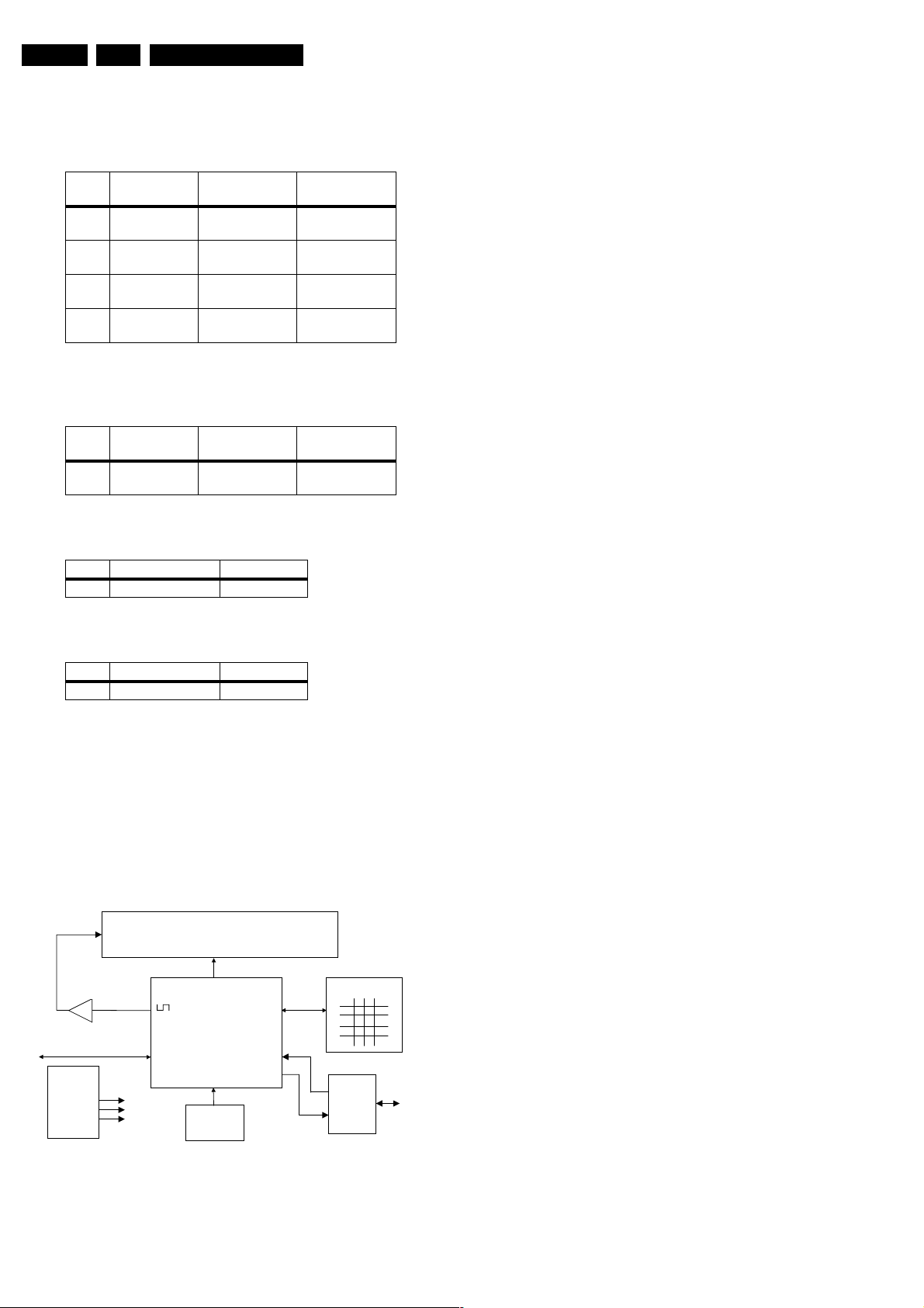
GB 30 DVD703 /XX15.
Diagnostic software descriptions and troubleshooting
5.7.5 Play and 16/9 detection
Check DC voltage at S-Video-chroma output (pin 4) with a
6K8 ohm load and Scart connector (pin 8) and change the 0/
6/12 input (1010-8) using the following commands:
Command
Ref.#
Name Remarks Chroma output
25a VideoScartLo Sends out 0V ±
0.5V
25b VideoScartMi Sends out 6V ±
10%
25c VideoScartHi Sends out 12V ±
10%
5.7.6 Kill circuit
To check the functionality of the Kill circuitry,the audio
outputs has to be present by the following command:
Command
Ref.#
Name Remarks Audio output
21a AudioPinkNois
Audio Pinknoise ONPink Noise on 6
eOn
Check the audio outputs at the audio cinch of the A/V board
: Pink Noise
Activate the Kill circuit by using the following command:
Ref.# Command Name Remarks
19a AudioMuteOn Audio Mute On
<0.1V
2.0V ± 10% with
load
5.0V ± 10%
without load
<0.1V
channels
5.8.2 Functionality description:
The essential component of the display PCB is the µP
(slave). This slave works on an 8MHz resonator and has a
reset circuit that is triggered by the +5Vstby. After the reset
pulse, the standby control line will release the reset of the
host µP. This host µP will then initialise the slave. In addition,
when going to stand-by, the slave will put the host µP in reset.
When the slave receives the right IR or key code to leave the
standby mode, the reset of the host µP will be released.
Other slave functions are:
• Square signal generator to generate the filament voltage,
which is required for an AC FTD.
• Generates the grid and segment scanning for the FTD.
• Generates a scanning grid for the keys (separated from
display scanning).
• Has inputs for RC (RC5 and RC6) and P50 (P50
controller is built in).
5.8.3 General
• Oscilloscope measurements have been carried out using
a Philips PM3392A.
• Impedance of measuring-equipment should be > 1MΩ.
• To do correct measurements we recommend to use
supply 3122 427 22600.
Check the audio outputs at the audio cinch of the A/V board
: No waveform
Switch off the kill circuit by using the following command:
Ref.# Command Name Remarks
19b AudioMuteOff Audio Mute Off
Check the audio outputs at the audio cinch of the A/V board
: Pink Noise
5.8 Test instructions Display board
5.8.1 Introduction
These test instructions are written for all versions of the
display PCBAS.
The contents of the PCB can be split up into next blocks:
V filament
V filament
Buffer
I2C
Display
µ
Processor
Key-matrix
Supply:
+5Vstby
+12V
-40V
RC-Eye
Figure 5-41
P50
I/O
CL 96532065_058.eps
130799
Page 31
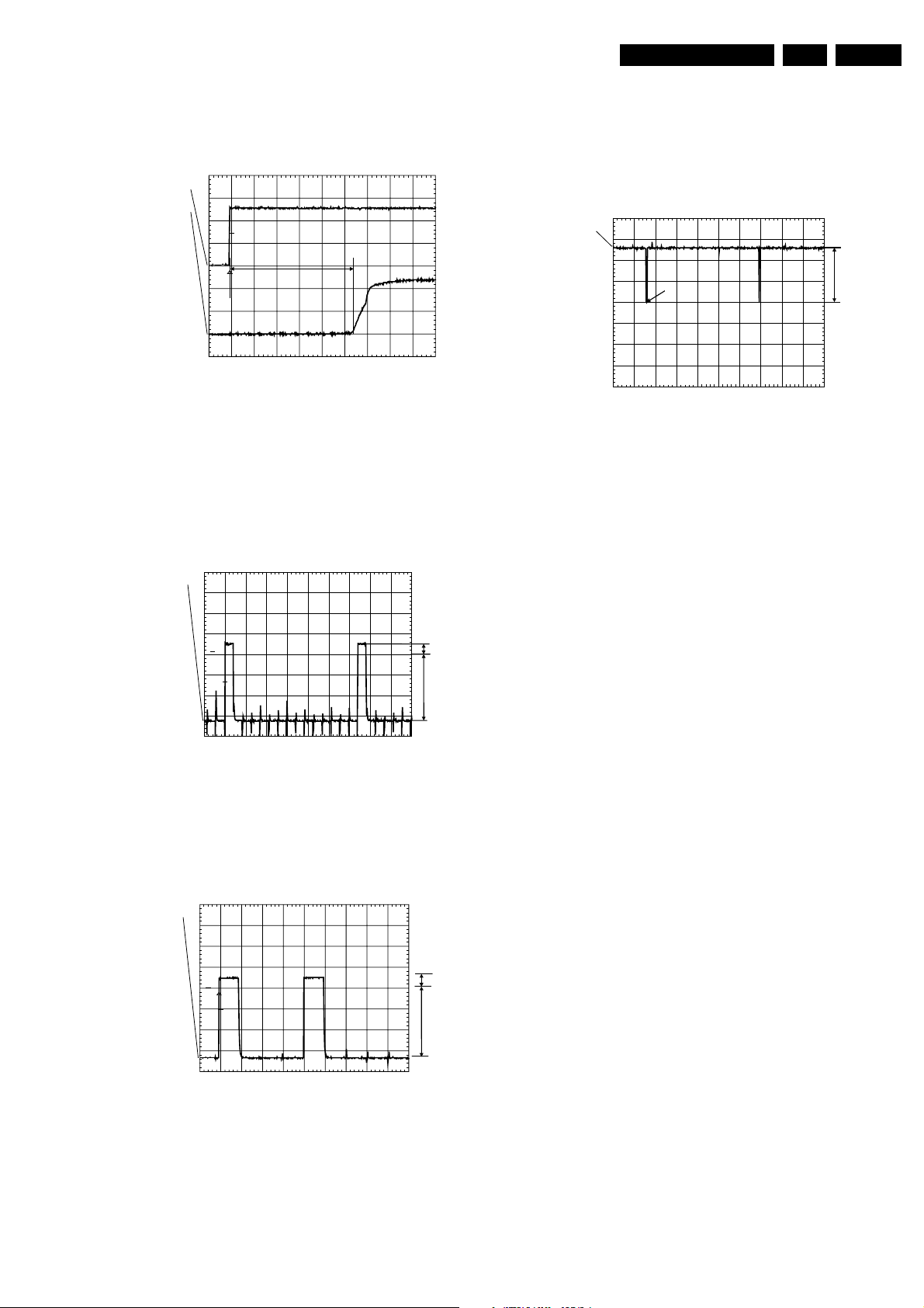
Diagnostic software descriptions and troubleshooting
GB 31DVD703 /XX1 5.
5.8.4 Reset
Check next reset timing with an oscilloscope at pin 10 of the
microprocessor.
PM3392A
ch2
ch1
T
2
1
CH1 2.00 V=
CH2 2 V= BWL MTB 100ms- 1.04dv ch2+
T1
CL 96532065_073.eps
Figure 5-42
Timing: 400msec < T1 > 700msec.
CH1: +5Vstby voltage at power on.
CH2: Voltage at pin 10.
5.8.5 Display steering
Check next timing and level for all grid-lines (G1 r G14).
PM3392A
ch1: low =-34.2 V
ch1
ch1: high= 3.98 V
130799
See the Slave URS how to send a display command.
5.8.6 Key-matrix
Connect a extra 10kΩ pull-up to pin 36 en 37 of the µP and
check next matrix scanning at these pins.
PM3392A
ch1: low =-46.9mV
ch1
ch1: high= 5.09 V
1
STOP
CH1 2.00 V= MTB10.0ms ch1-
B
CL 96532065_076.eps
Figure 5-45
Level A: 5.0V +/-7%
Level B: 0V +/-200mV
Check matrix scanning from pin 26 until 33 of the µP.
The results should be the same as the diagram above.
5.8.7 I.R. receiver
Check at pin 23 of the µP if this line switches from low (<
0.3V) to high (> 4.5V), while pressing a key on a Philips RC5
or RC6 remote control.
A
130799
1
T
STOP
CH1 10.0 V= MTB 200us 2324us ch1+
CL 96532065_074.eps
A
B
130799
Figure 5-43
1. Check level A: +4V5 +/-10% for grid lines 1 => 11
2. Check level A: +4V0 +/-10% for grid lines 12 => 14
3. Check level B: -33V +/-10%
4. Check timing and levels of segment-lines P1 => P10:
PM3392A
ch1
1
T
CH1 10.0 V= BWL MTB 500us- 1.04dv ch1+
CL 96532065_075.eps
A
B
130799
Figure 5-44
Level A:+4V5 +/-10%
Level B:-33V +/-10%
The data on these segment lines depend on the characters
that are displayed.
The characters can be set by sending I2C commands to the
display.
5.8.8 Karaoke interface
The karaoke interface (4 lines) is a single direction
communication.
This means that it consists of four µP output lines.
The interface can be checked by setting or resetting these
output-ports via the I2C bus.
Send next command via the I2C bus:
Address : 0x70
Command byte : 0x24
Data byte : xxxxabcd
Where : a = Karaoke reset.
: b = Karaoke data.
: c = Karaoke clock.
: d = Karaoke strobe.
5.8.9 P50 interface
P50 is a bi-directional serial interface, which is used for
communication between video equipment. For European
sets, this communication goes via pin 10 of the scart-bus. In
other regions, it can be a cinch bus at the back of the set.
1. Keep the µP in reset by short-circuiting emitter and
collector of transistor 7108, via resistor 3100 and 3104
transistor 7101 is switched on.
2. Check the voltage at the P50 output connector 1118-5: <
200mV.
When the reset is released the µP output-pin becomes low
and transistor 7101 is switched off.
1. Check the voltage at the P50 output connector 1118-5:
4V9 +/-5%.
2. Check also the µP P50 input (µP pin 20): 5V +/-5%.
3. Connect the P50 line (connector 1118-5) to ground.
4. Check again the µP P50 input (µP pin 20): <0V3.
Page 32
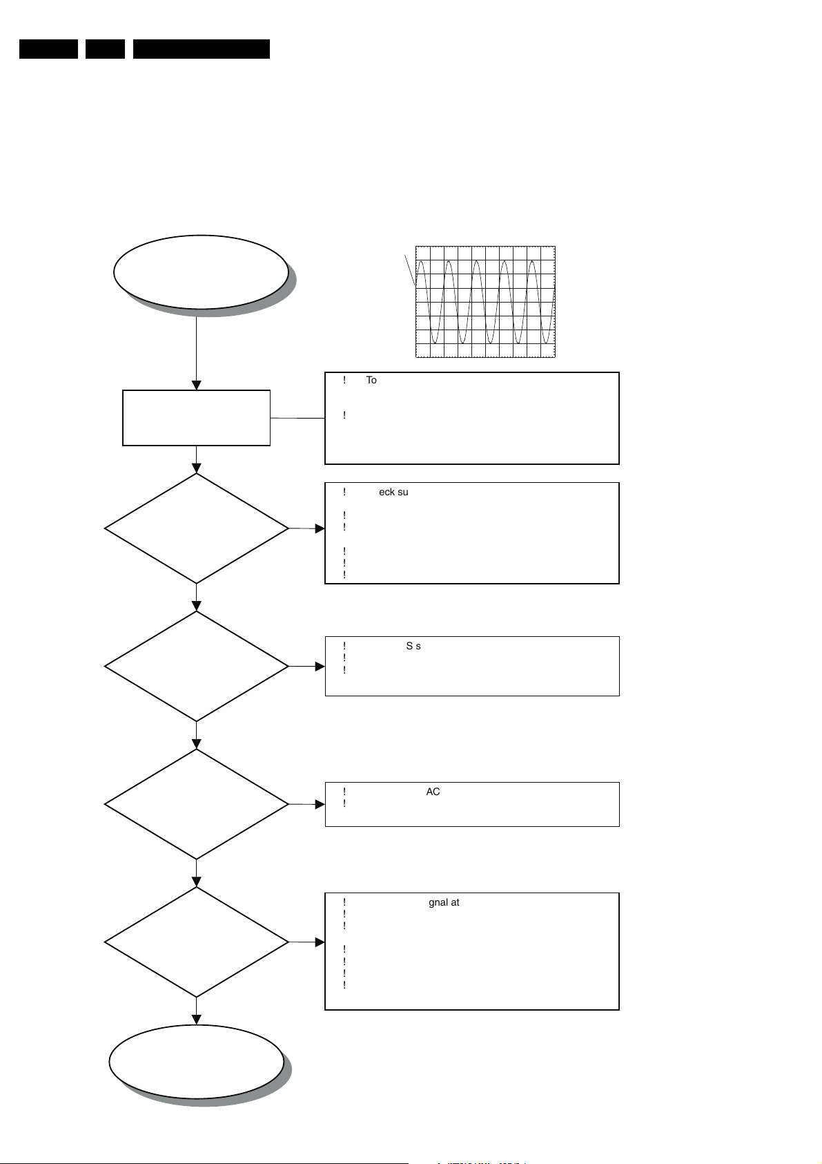
GB 32 DVD703 /XX15.
Diagnostic software descriptions and troubleshooting
5.9 Troubleshooting
5.9.1 Troubleshooting A/V board
Testing of A/V board can be done using diagnostic software
“PLAYER SCRIPT”.
MONO board is used to generate a sound with the sound
tests SND-1 and SND-2 or a VIDEO signal with the picture
“DIAGNOSTIC SOFTWARE: SCRIPT INTERFACES”.
AUDIO PART OF AUDIO/VIDEO BOARD 3139 243 30161
START
NO SOUND OUTPUT
ON AUDIO CINCH
1008B/C
!!To activate the "Player Script ",press Open/Close and
ACTIVATE
DIAGNOSTIC SOFTWARE
“ PLAYER SCRIPT “
PM3380B
ch1
1
CH11.00V~MTB500usch1+
TP13: ANALOG OUTPUT AUDIO L/R
Stop keys on the local keyboard of the DVD player
simultaneously.
Proceed to the nuclei "AudioPinkNoise" by pressing
NEXT key until display shows "APP SND-1" and
seconds later it show " Scart DVD "
CHECK
POWER SUPPLY
3V3_A and 3V3_B
TO DAC ?
YES
CHECK
AUDIO I2S
SIGNAL TO DAC
YES
CHECK
DAC OUTPUT
AT TP12
YES
!
NO
NO
?
Check supply voltages at connector 1001
Pin 9 -> -5Vstdby
!
Pin 10/11 ->+5V
!
Check 3V3 regulator 7010 and safety resistor 3213 ,
3229
!
Check the delay cct 7456 , 3230 , 3231 , 2231
!
Check the Flex cable to connector 1001
!
Check Mono Board
!
Check I2S signal at testpoints 7 , 8 , 9 , 10
!
Check the Flex cable to connector 1001
!
Check Mono Board
NO
!!Check Vref-DAC on Pin 12 of DAC IC 7011 1V6
Check for malfunction of DAC IC 7011
?
END
CHECK
AUDIO CINCH
OUTPUT-> TP 13
?
YES
SOUND ON
AUDIO CINCH 1008
OK
NO
Check KILL signal at Pin 12 connector 1001
!
Audio mute OFF -> -8V ± 10%
!
Check for malfunction of KILL transistor 7451 , 7452 ,
!
7453 ,7454
!
Check ± 5V supply to OP-AMP 7012
!
Check gain configuration of OP-AMP 7012
!
Check for malfunction of OP-AMP 7012
!
Check Mono Board
CL 16532007_012.eps
130201
Page 33
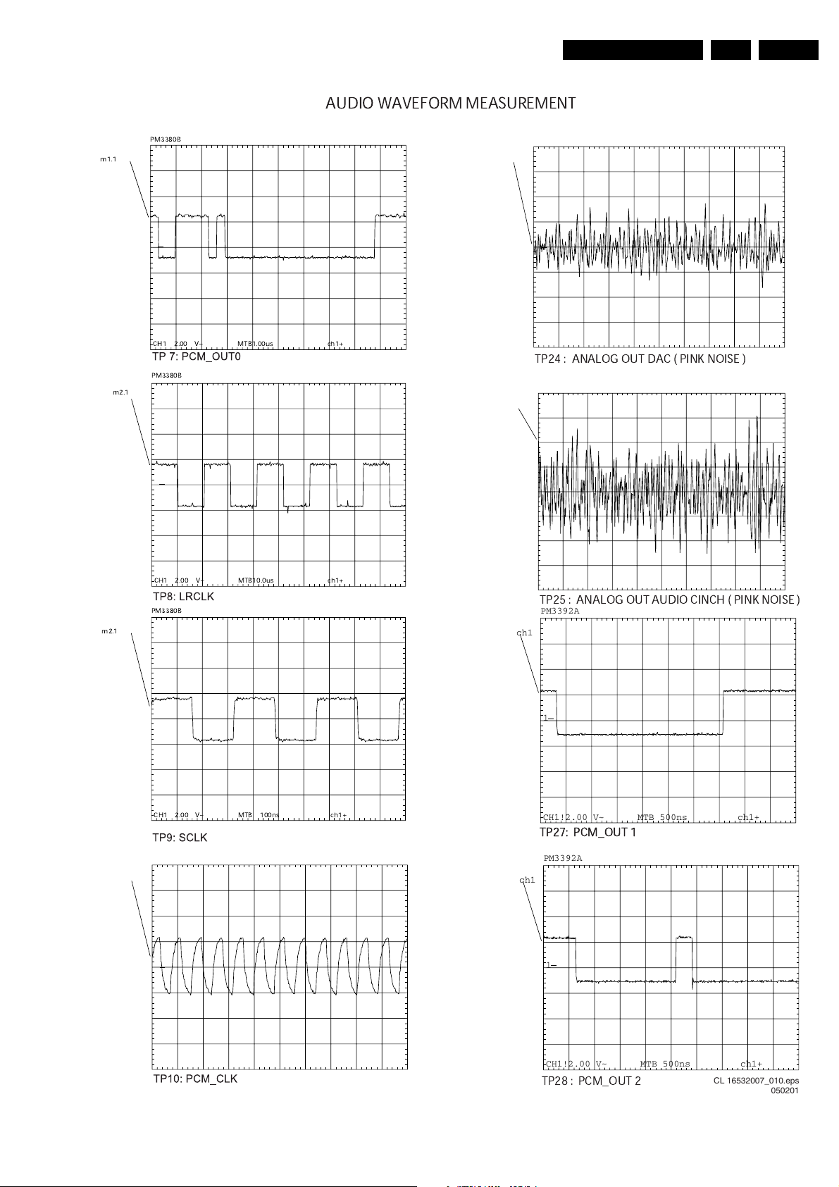
Diagnostic software descriptions and troubleshooting
TP27: PCM_OUT 1
AUDIO WAVEFORM MEASUREMENT
GB 33DVD703 /XX1 5.
m1.1
PM3380B
CH1 2.00 V~ MTB1.00us ch1+
PM3380B
m2.1
PM3392A
PM3392A
ch1
ch1
1
1
CH1!2.00 V~ MTB 500ns ch1+
CH1! 200mV~ MTB10.0ms ch1+
TP24 : ANALOG OUT DAC ( PINK NOISE )
PM3392A
PM3392A
ch1
PM3392A
1
1
1
ch1
ch1
m2.1
ch1
CH1 2.00 V~ MTB10.0us ch1+
PM3380B
CH1 2.00 V~ MTB 100ns ch1+
PM3392A
1
ch1
ch1
CH1!2.00 V~ MTB 500ns ch1+
CH1! 200mV~ MTB10.0ms ch1+
CH1! 200mV~ MTB10.0ms ch1+
TP25 : ANALOG OUT AUDIO CINCH ( PINK NOISE )
PM3392A
1
CH1!2.00 V~ MTB 500ns ch1+
TP27: PCM_OUT 1
PM3392A
1
CH1 2 V~ MTB 100ns ch1+
CH1!2.00 V~ MTB 500ns ch1+
TP28 : PCM_OUT 2
CL 16532007_010.eps
050201
Page 34
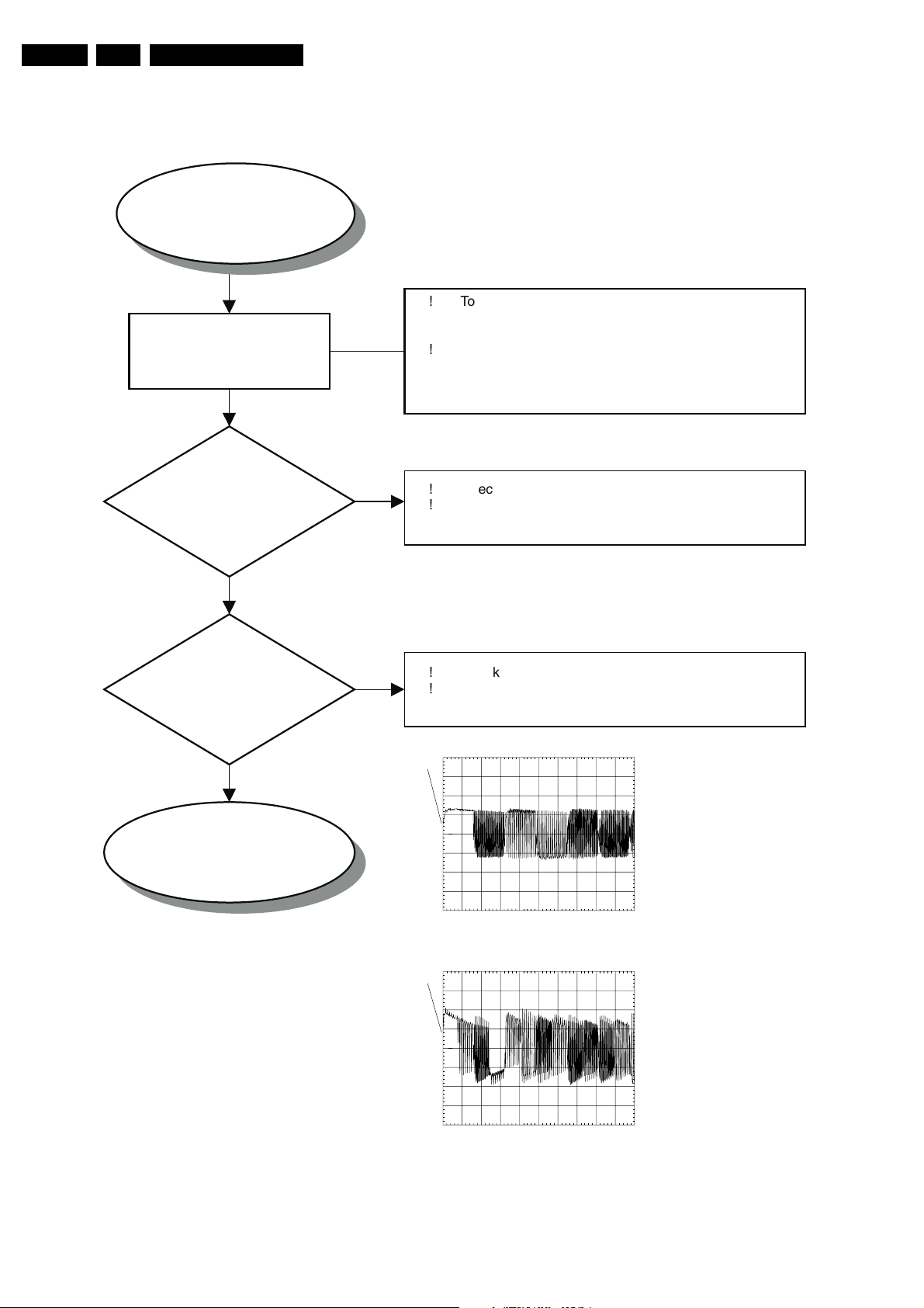
GB 34 DVD703 /XX15.
Diagnostic software descriptions and troubleshooting
AUDIO PART OF AUDIO/VIDEO BOARD 3139 243 30161
START
NO DIGITAL OUTPUT
ON COAXIAL
1011
ACTIVATE
DIAGNOSTIC SOFTWARE
“ PLAYER SCRIPT “
CHECK
DIG_OUT AT
TP11
?
YES
CHECK
DIGITAL COAX
OUTPUT AT TP21
?
!!To activate the "Player Script ",press Open/Close and
Stop keys on the local keyboard of the DVD player
simultaneously.
Proceed to the nuclei "AudioPinkNoise" by pressing
NEXT key until display shows "APP SND-1" and
seconds later it show " Scart DVD ".
NO
!!Check Flex cable to connector 1001.
Check Mono Board.
NO
!!Check coupling transformer 5008.
Check coupling components 3225, 3226, 2225.
END
DIGITAL OUT
OK
PM3392A
ch1
1
CH1 2 V~ MTB 100ns ch1+
TP 11: DIG_OUT
PM3392A
ch1
1
CH1 200mV~ MTB 200ns ch1+
TP 21: DIGITAL OUT
CL 16532007_069.eps
130201
Page 35
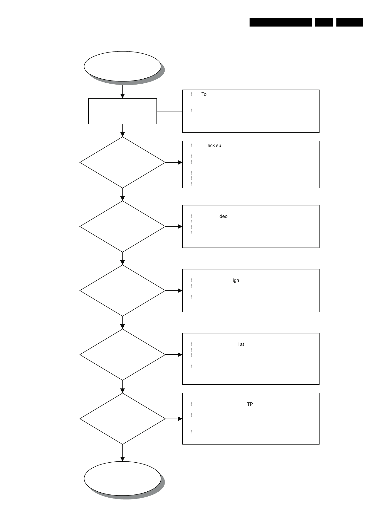
Diagnostic software descriptions and troubleshooting
VIDEO PART OF AUDIO/VIDEO BOARD 3139 243 30161
GB 35DVD703 /XX1 5.
START
NO PICTURE
CVBS , Y/C , YUV
ACTIVATE
DIAGNOSTIC SOFTWARE
“ PLAYER SCRIPT “
CHECK
POWER SUPPLY
±5V AND 3V3
?
YES
CHECK
VIDEO INPUT AT
CONN 1000 &
1001 ?
NO
NO
!!To activate the "Player Script ",press Open/Close and
Stop keys on the local keyboard of the DVD player
simultaneously.
Proceed to the nuclei "VideoColDencOn" by pressing
NEXT key until display shows "APP PIC-1"
!
Check supply voltages at connector 1001
Pin 9 -> -5Vstdby
!
Pin 10/11 -> +5V
!
Check 3V3 regulator 7010 and safety resistor 3213 ,
3229
!
Check the delay cct 7456 , 3230 , 3231 , 2231
!
Check the Flex cable to connector 1001
!
Check Mono Board
Check video signal at TP1 B_Vid , TP2 G_Vid
!
TP3 R_Vid , TP4 CVBS , TP5 C , TP6Y
!
Check the Flex cable to connector 1001 & 1000
!
Check Mono Board
!
YES
CVBS CINCH
OUTPUT AT
CONN 1008A ?
YES
Y/C OUTPUT AT
CONN 1003
YES
YUV OUTPUT AT
CONN 1006
CHECK
CHECK
?
CHECK
?
NO
NO
NO
!
Check CVBS signal at testpoint 14
!
Check for ±
5V supply to Video buffer amplifier
Check for malfunction of Video buffer amplifier 7411,
!
7412 , 7413 , 7414 and the biasing configuration
!
Check Y /C signal at TP 16 and TP15 respectively
!
Check for ± 5V supply to Video buffer amplifier
!
Check for malfunction of Video buffer amplifier 7407,
7408,
!
7410, 7457, 7458, 7455 and the biasing
configuration
!
Check YUV signal at TP 17, TP18 and TP19
respectively
Check for ±
!
5V supply to OPAMPS 7001 and transistor buffer
7415
Check for malfunction of OPAMPS 7001 and
!
transistor buffer 7415
END
YES
VIDEO PART
OK
CL 16532007_017.eps
070201
Page 36
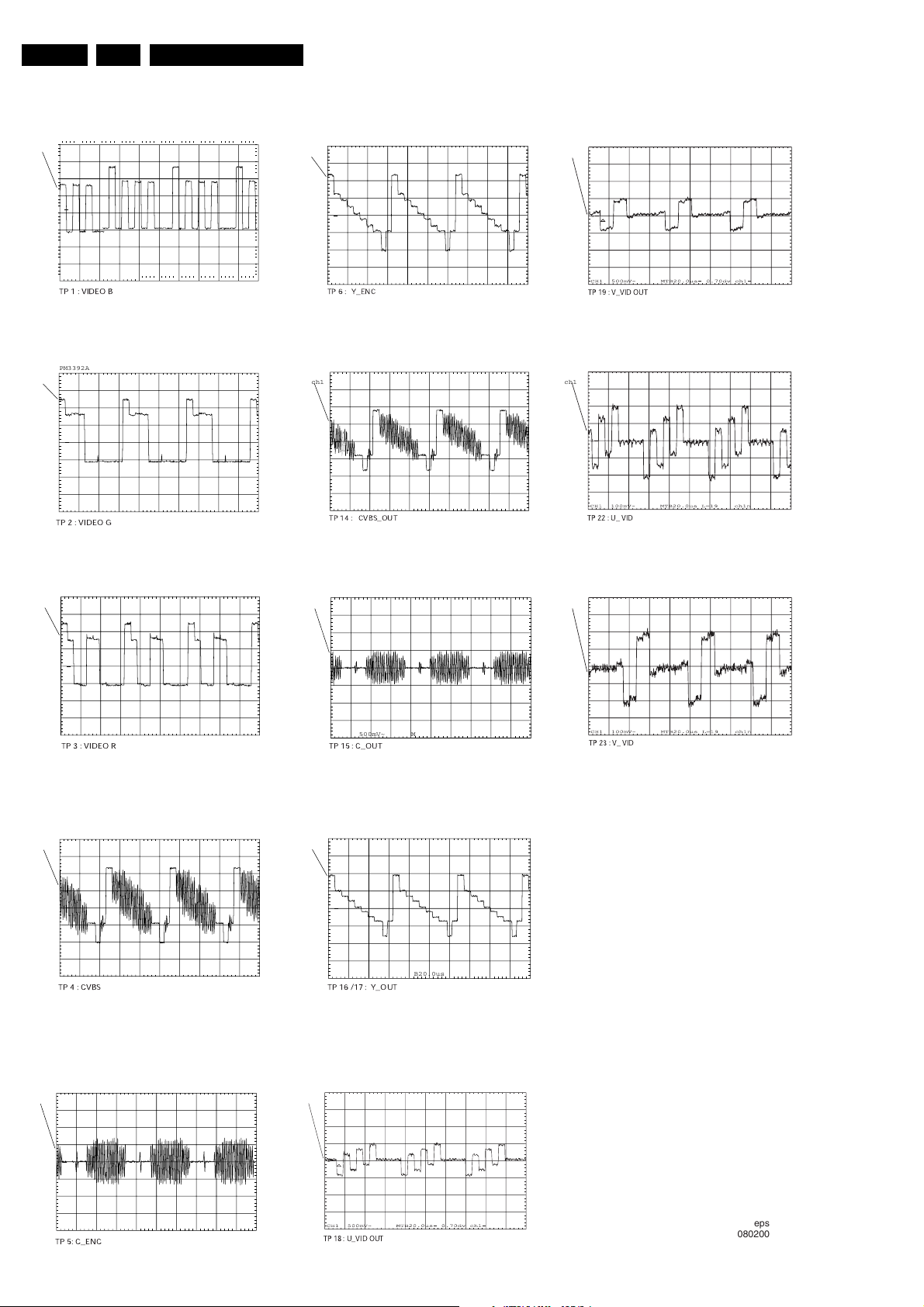
GB 36 DVD703 /XX15.
VIDEO WAVEFORM MEASUREMENT
PM3392A
ch1
Diagnostic software descriptions and troubleshooting
PM3392A PM3380B
ch1 ch1
1
CH1 200mV~ MTB20.0us ch1+
TP 1 : VIDEO B
PM3392A
ch1
1
CH1 200mV~ MTB20.0us ch1+
TP 2 : VIDEO G
PM3392A
ch1
1
CH1 200mV~ MTB20.0us ch1+
TP 6 : Y_ENC
PM3392A
ch1 ch1
1
CH1 500mV~ MTB20.0us ch1+
TP 14 : CVBS_OUT
PM3392A
ch1
ch1
TP 19 : V_VID OUT
PM3380B
TP 22 : U_ VID
PM3380B
1
CH1 200mV~ MTB20.0us ch1+
TP 3 : VIDEO R
PM3392A
ch1
1
CH1 200mV~ MTB20.0us ch1+
ch1
TP 4 : CVBS
PM3392A PM3380B
ch1 ch1
1
CH1 500mV~ MTB20.0us ch1+
TP 15 : C_OUT
PM3392A
1
CH1 50mV~ MTB20.0us ch1+
TP 16 /17 : Y_OUT
TP 23 : V_ VID
1
CH1 200mV~ MTB20.0us ch1+
TP 5: C_ENC
TP 18 : U_VID OUT
CL 16532007_058.eps
080200
Page 37
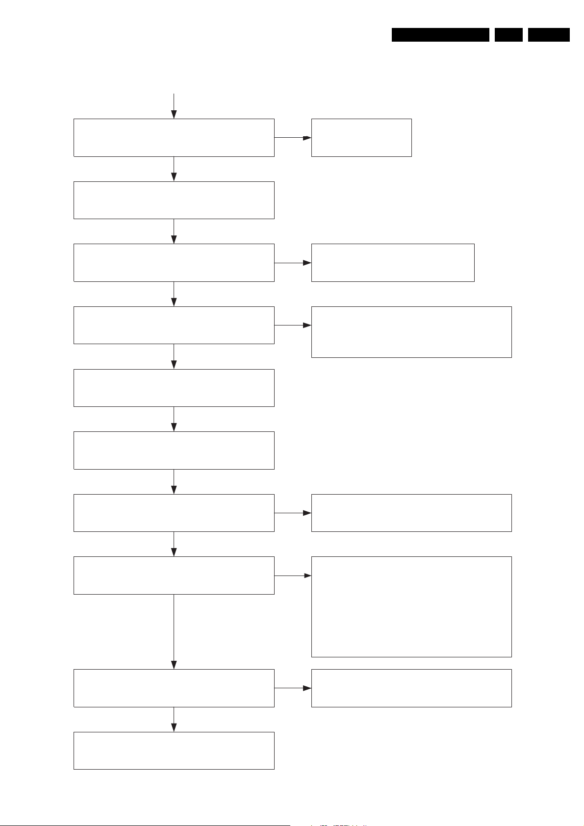
Diagnostic software descriptions and troubleshooting
TROUBLESHOOTING POWER SUPPLY UNIT VFM WR
START
GB 37DVD703 /XX1 5.
Check DC voltages
+12V, +5Vstdby, -8Vstdby, +5V,+3V3
NOK
Disconnect the power supply from the MAIN Board
Connect dummy load resistors 10W ( min 5W ) :
10 ohm at +3V3, 15 ohm at +12V and ground
Check DC voltages
+12V, +5Vstdby, -8Vstdby, +5V, +3V3
These voltages will be somewhat higher than specified
NOK
Check the +3V3 and +12V
NOK
Check +12V path : D6241, C2240, L5240
Check +3V3 path : D6210, C2210, L5210
OK
Power Supply
OK
OK
OK
Power Supply OK
Check : Mono Board
A/V Mux Board
Display Board
Check the path of the faulty voltages:
+5V path: D6230, C2230, L5231, T7238, C2238, C2239
-5V path: D6250, C2250, L5222 and T7255 regulator unit
+5V_stby path: R3233, D6233
OK
Connect the mains inlet to a mains isolated variac
Turn input voltage up and check across C2121
the voltage should be
+/-1.41 X Vin AC
OK
Is power supply ticking?
NO
Check supply voltage on pin 7 of IC7145
Vcc within 10V - 16V (typical )
NOK
YES
NOK
Check the functionality of the following components:
F1120, R3122, L5120, D6120, C2121
Check the load on the secondary output
Check overvoltage protection:
D6141, R3139, T7141, T7150, R3150
Check oscillator voltage on pin 4 of IC7145
Check R3146,C2157 and replace IC7145
Check drive circuit : gate voltage of Mosfet 7125,
components R3111, R3140, R3156,R3125,D6140
Check working of regulation circuit :
T7131,T7201,R3201,R3202,R3204,R3205,
R3206,R3207,R3208,R3153,R3154,R3262,C2202
Check start-up circuit and Vcc supply circuitry
Replace IC7145
OK
Power Supply Unit
OK
CL16532007_070.eps
160201
Page 38

GB 38 DVD703 /XX15.
Personal notes:
Diagnostic software descriptions and troubleshooting
Page 39
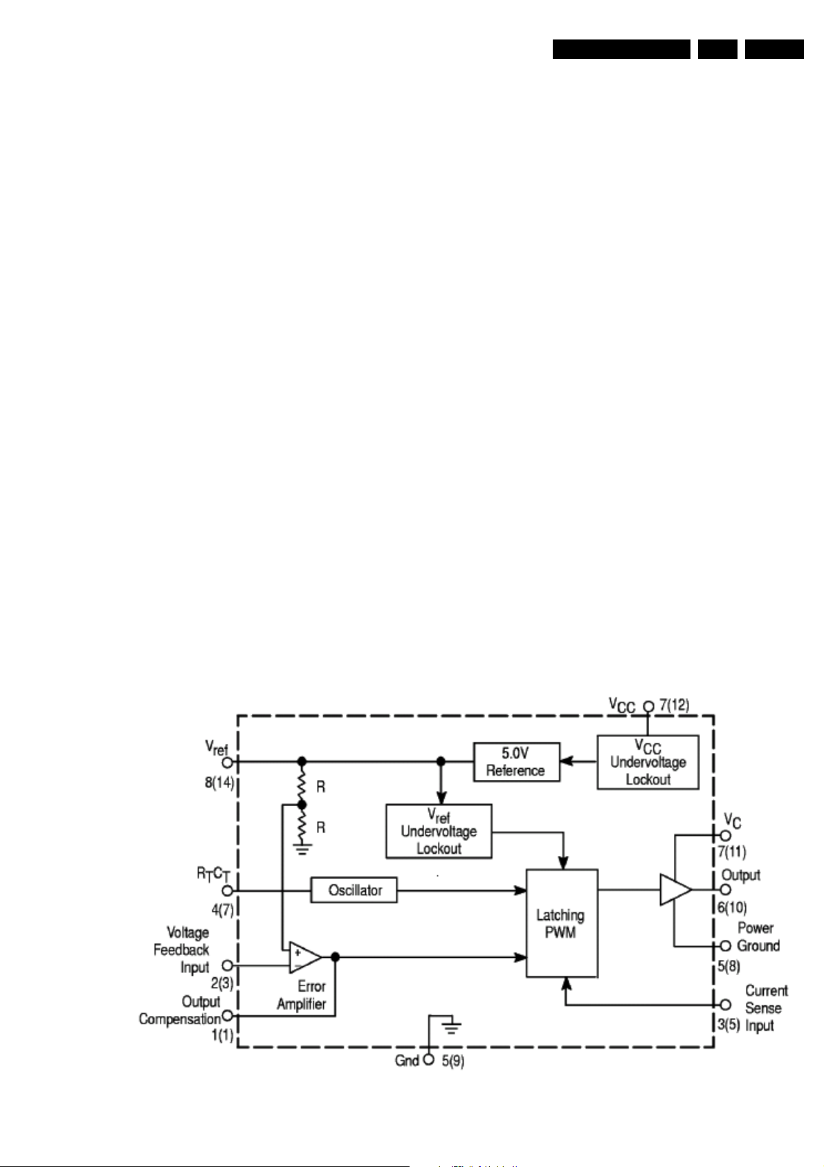
Alignments
8. Alignments
No electrical alignments available
9. Circuit descriptions and list of abbreviations
9.1 Current mode Power Supply
9.1.1 Introduction
The switch mode power supply ( SMPS ) is mains isolated.
The control IC 7145 ( UC 3842A ) produces pulses to drive
the power switch, Mosfet 7125.
Power supply regulation is achieved by using duty cycle
control at fix frequency ,of approximately 58KHz ,determined
by the RC timing components.
9.1.2 General Description of UC 3842A
The UC 3842 is a high performance fixed frequency current
mode controller that is specifically designed for off-line and
DC-to-DC converter application. This integrated circuit
feature a trimmed oscillator for precise duty cycle control, a
temperature compensated reference, high gain error
amplifier, current sensing comparator and a high current
totem pole output ideally suited for driving a power MOSFET.
Also included are protective features consisting of input and
reference undervoltage lockouts each with hysteresis, cycle
by cycle current limiting, programmable output deadtime and
a latch for single pulse metering.
A representative Block diagram and Pin function description
is shown in Fig 1 and Fig 2 respectively.
GB 51DVD703 /XX1 8.
9.1.3 BLOCK DIAGRAM
Figure 9-1
CL06532096_010.eps
060700
Page 40
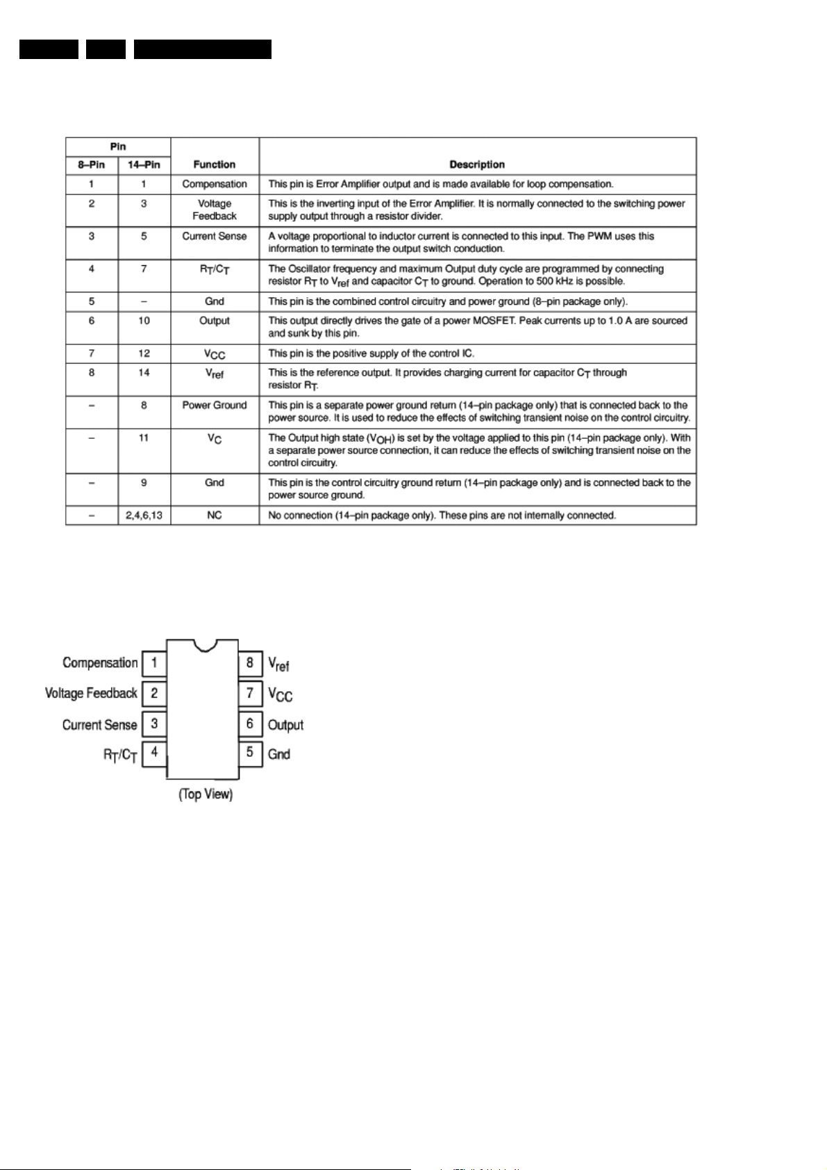
GB 52 DVD703 /XX19.
9.1.4 Pin function description
Circuit descriptions and list of abbreviations
9.1.5 Pin connection
CL06532096_012.eps
Figure 9-3
9.1.6 Output voltages
• +12V ( For Display board, Monoboard, A/V board )
created via D6241, C2240, L5240, C2232 (This voltage
is also present during standby)
• +5V_ stdby ( For Display board, Standby PCB,
Monoboard ) created from +6V via R3233 and D6233
(This voltage is also present during standby)
• +6V_stdby ( Reserve ) created from D6230, C2230,
L5231 (This voltage is also present during standby)
• +5V ( For Monoboard, A/V board ) derive from +6V stdby
via Mosfet 7238, C2239 and it will be switch off via
R3235, T7235 during Standby.
• -5V ( For Monoboard, A/V board ) created from D6250,
C2250, C2259, L5222, R3259, T7255 regulator circuit
and will switch off via R3258, T7257 during standby
(control signal Standby is HIGH)
060700
Figure 9-2
CL06532096_011.eps
• 3V3 ( For Monoboard, A/V board ) The 3V3 power
supply is regulated by the control loop comprising of
7201, 7131 and 7145 of the switch mode PSU. This
voltage is also present during standby
• -40V ( For Display board ) created via D6261,R3260,
L5260, C2260 This will not be present during standby
9.2 CONTROL CIRCUITRY
9.2.1 Mains input circuit
The mains voltage is rectified by bridge rectifier (D6118 to
D6121) and filter by C2121. The DC voltage across C2121is
the DC input voltage ,approximately 300V, is the DC input to
pin 1 of transformer T5131.The mains input also consists of
a lighting protection R3120.
9.2.2 Start-up and takeover circuitry
The start-up circuitry consist R3123, R3134, R3111, D6129,
C2134 and with the mains voltage input, the C2134 will
charge via R3123 and R3134. When the voltage at pin 7 of
IC7145 reaches the start-up threshold of min 14.5V,
IC7145 will start-up and the control circuit start to operate.
After start-up, the max sinking current of 17mA is required by
IC7145 which is not able to be delivered by the start-up
circuitry, so the takeover circuitry must be present.
If the takeover circuit does not occurred, the supply voltage
at pin 7 will decrease gradually till it reaches the IC7145
minimal operating voltage of 8.5Vand the IC will switch off.
The whole operation cycle will repeat itself with audible
hiccup sound if takeover is not present.
The takeover circuit comprises of D6133, R3135, l5135,
C2134. During the control circuit start-up, the voltage across
winding pin 7 and 9 will gradually built up and charged C2134
060700
Page 41
Circuit descriptions and list of abbreviations
GB 53DVD703 /XX1 9.
via D6133, R3135 which will takeover the supply voltage of
T7145 at pin 7.
9.2.3 Secondary voltage sensing
The secondary voltage regulating circuit comprise of the
opto-coupler 7131 which isolate the error signal from the
control IC7145 ,on the primary side, and a reference
component 7201 ( TL431 ). The 7201 can be represented by
two components:
• A very stable and accurate reference diode
• A high gain amplifier
K
R
2.5V
A
CL 96532065_071.eps
Figure 9-4
When the output voltage increases, due to a reduction in the
load, the voltage across R3205 and R3206 increases to
above the internal reference voltage of about 2.5V then
TL431 conduct. The current through the opto-coupler 7131
will increase due to the fact that the series resistor in 7201
decreases. This result in a increase of voltage to pin 2 of
IC7145, thus reducing the on-time of FET 7125.
In the event of a decrease in output voltage (increase in load
),the control circuit will operate in the opposite way to the
explaination above.
130799
it goes into the overvoltage protection and a complete restart
sequence is required.
9.2.4 Primary current sensing
The current through the FET 7125 resulting in a voltage drop
across R3126,R3127,R3128 which is couple to pin 3 of
IC7145,current sense input.The higher the input voltage, the
more the primary current is limited. In this way the maximum
output power of the power supply is limited.
9.2.5 Undervoltage protection
Two undervoltage lockout comparators have been
incorporated to guarantee that the IC7145 is fully functional
before the output stage is enable. The supply voltage at pin
7 and reference voltage at pin 8 of IC7145 are each
monitored by separate comparators with built-in hysteresis.
If the supply voltage at pin 7 of IC7145 drops below 10V (
typical ), due to a secondary voltage is short-circuit or
excessive load, the drive pulse at pin 6 of IC7145 will be
disabled and the controller will switch off the complete
SMPS.
Remarks : In the event of the overvoltage situation remaining
present, the SMPS will go in sequence of protection,start- up
cycle, protection and the cycle repeats. This effect is highly
audible.
9.2.6 Overvoltage protection
The overvoltage circuitry comprising of D6141,R3139,
R3150, R3141,T7141, T7150 which is used to detect an over
voltage situation on the secondary side of the transformer.
After start-up, when the voltage across C2135 exceeds
18V,the overvoltage circuit will trigger the internal latch
circuit, pin 1 of IC7145 and the output buffer is disabled and
Page 42

GB 54 DVD703 /XX19.
9.3 List of abbreviations
Circuit descriptions and list of abbreviations
B Buffered Video input Blue from DVD
BC_AUX Blue or Chroma input from AUX-
BC_TV Blue or Chroma output to TV-scart
C_ENC Buffered Chroma input from DVD
CVBS Buffered Composite video input from
DC_OFF Control signal to switch off û8Vstby
DIG_OUT Digital out
FBIN_AUX Fast blanking input from AUX-scart
FBOUT_TV Fast blanking output to TV-scart
G Buffered Video input Green from
GIN_AUX Video input Green from AUX-scart
GOUT_TV Video output Green to TV-scart
HP_L Audio output left to headphone and
HP_R Audio output right to headphone and
KILL Kill control signal for audio outputs
LIN_AUX Audio input left from AUX-scart
LIN_TV Audio input left from TV-scart
LOUT_AUX Audio output left to AUX-scart
LOUT_TV Audio output left to TV-scart
LRCLK Left/Right clock
PCM_CLK Audio system clock for DAC
PCM_OUT0 Audio serial output data
R Buffered Video input Red from DVD
RCIN_TV Red or Chroma input from TV-scart
RCOUT_TV Red or Chroma output to TV-scart
RIN_AUX Audio input right from AUX-scart
RIN_TV Audio input right from TV-scart
ROUT_AUX Audio output right to AUX-scart
ROUT_TV Audio output right to TV-scart
SCL I2C bus clock
SCLK Audio serial bit clock
SDA I2C bus data
SELECT Control signal for video scart
SELECT_HIGH Control signal for switching fast
SLB_AUX Slow blanking control signal from
SLB_TV Slow blanking control signal to TV-
STANDBY Control signal from STI5505 used to
STEREO_L Audio cinch output left
STEREO_R Audio cinch output right
Y_ENC Buffered Luma input from DVD
YCVBSIN_AUX Luma or CVBS input from AUX-scart
YCVBSIN_TV Luma or CVBS input from TV-scart
YCVBSOUT_AUX Luma or CVBS output to AUX-scart
YCVBSOUT_TV Luma or CVBS output to TV-scart
0/6/12 Scart switch control signal A/V
monoboard
scart
monoboard
DVD monoboard
and +12Vstby during standby
DVD monoboard
audio scart switch TEA6420
audio scart switch TEA6420
and for soft mute of DAC
monoboard
switches; high = TV ,low = AUX
blanking and slow blanking signals;
high = TV,.low = AUX
AUX-scart
scart
swith off û8Vstby and +12Vstby
during standby.
monoboard
board. 0V : loop through (AUX to
TV), 6V : play 16:9 format, 12V : play
4:3 format
Page 43
10. Spare parts list
Spare parts list
GB 55DVD703 /XX1 10.
Various
Various
0010 3139 247 53451 CAB FRONT DVD703/69X
0015 4822 459 10887
0030 3139 247 53141 WINDOW DVD733K/69X
0035 3139 247 53501 RING DVD703/69X PPT
0040 3139 247 50880 BTN CONTROL DVD751/
0045 3139 240 00030 DVD LOGO DVD711
0050 3139 247 50940 DOOR DVD751/00X PNT
0060 3139 241 20110 DOOR SPRING
0200 3139 247 53391 FRONT ASSY DVD703/
0205 3139 247 53161 BTN POWER DVD733K/
0224 3139 247 53231 BACK PLATE DVD703/17X
0232 3139 247 51170 COVER TOP DVD751/
0244 3139 247 50760 FOOT ASSY DVD751
0245 3139 247 50760 FOOT ASSY DVD751
0265 4822 321 11139 POWER CORD
0381 2422 076 00304 CABLE CINCH/CINCH
0384 3139 228 87041 PROD.ASSY RC19137001/
0387 3139 246 10981 IFU DVD703/03X
1002 3139 248 81191 PCBAS AV DVD 703 AP
1003 3139 248 80951 PCBAS FR DVD712 AP
1005 3122 427 22600 PSU DVD VFM WR
1014 4822 320 12674 CWAS FFC BD 22P 14P
1018 3139 110 34230 FFC FOIL 16P/105/16P BD
PPT
PPT
00X PNT PRT
PRT
69X
69X PPT
PPT
OOX PNT PRT
1M5 YE/RD/WH
01 PACKED
SD1
B
AV PWB
Various
1000 2422 025 16525 CON BM V 16P F 1.00 FFC
1001 2422 025 16526 CON BM V 22P F 1.00 FFC
1003 4822 267 10994 4P, MDIN
1006 2422 026 05049 CON BM CINCH H 3P F
1008 4822 265 11566 3P YKC21-3930
1011 4822 267 31729
g
2002 4822 124 40207 100µF 20% 25V
2004 4822 124 40207 100µF 20% 25V
2007 3198 017 44740 0603 10V 470nF COL
2008 4822 124 23432 100µF 20% 10V
2009 4822 126 13883 220pF 5% 50V
2010 4822 126 13883 220pF 5% 50V
2012 4822 126 14494 22nF 10% 25V 0603
2013 4822 126 14494 22nF 10% 25V 0603
2200 4822 124 40207 100µF 20% 25V
2201 4822 126 14305 100nF 10% 16V 0603
2202 4822 124 11947 10µF 20% 16V
2203 4822 124 40207 100µF 20% 25V
2204 4822 124 40207 100µF 20% 25V
2205 4822 124 81286 47µF 20% 16V
2206 4822 126 14305 100nF 10% 16V 0603
2207 4822 124 81286 47µF 20% 16V
2208 4822 126 14305 100nF 10% 16V 0603
2209 4822 126 14305 100nF 10% 16V 0603
2210 4822 124 81286 47µF 20% 16V
2211 4822 126 14305 100nF 10% 16V 0603
2212 3198 016 31020 0603 25V 1nF
2214 4822 124 11947 10µF 20% 16V
2215 4822 124 40207 100µF 20% 25V
2216 4822 124 11947 10µF 20% 16V
2217 3198 017 44740 0603 10V 470nF COL
2222 3198 016 31020 0603 25V 1nF
2224 4822 126 14305 100nF 10% 16V 0603
2225 4822 124 11947 10µF 20% 16V
2226 4822 122 33777 47pF 5% 63V
2227 4822 126 14305 100nF 10% 16V 0603
2228 4822 122 33777 47pF 5% 63V
0.3 R
0.3 R
2229 4822 122 31765 100pF 2% 63V
2230 4822 122 31765 100pF 2% 63V
2231 4822 124 80791 470µF 16V 20% 105C
DXH=8X11.5
f
3002 4822 051 30472 4k7 5% 0.062W
3003 4822 051 30271 270Ω 5% 0.062W
3004 4822 051 30101 100Ω 5% 0.062W
3006 4822 051 30682 6k8 5% 0.062W
3007 2120 108 93892 RST SM 0603 820Ω PM1
3009 4822 051 30759 75Ω 5% 0.062W
3012 4822 051 30222 2k2 5% 0.062W
3013 4822 051 30222 2k2 5% 0.062W
3014 4822 051 30223 22k 5% 0.062W
3015 4822 051 30472 4k7 5% 0.062W
3016 5322 117 13051 680Ω 1% 0.063W 0603
3017 4822 117 12902 8k2 1% 0.063W 0603
3019 4822 051 30223 22k 5% 0.062W
3020 4822 051 30153 15k 5% 0.062W
3023 4822 051 30103 10k 5% 0.062W
3025 4822 051 30271 270Ω 5% 0.062W
3028 4822 051 30101 100Ω 5% 0.062W
3029 4822 051 30101 100Ω 5% 0.062W
3030 4822 051 30682 6k8 5% 0.062W
3031 2120 108 93892 RST SM 0603 820Ω PM1
3032 4822 051 30759 75Ω 5% 0.062W
3033 4822 116 83883 470Ω 5% 0.5W
3034 4822 051 30472 4k7 5% 0.062W
3035 5322 117 13051 680Ω 1% 0.063W 0603
3037 4822 050 11001 100Ω 1% 0.4W
3038 4822 050 11001 100Ω 1% 0.4W
3039 4822 051 30759 75Ω 5% 0.062W
3040 4822 050 12202 2k2 1% 0.4W
3041 4822 051 30392 3k9 5% 0.063W 0603
3042 5322 117 13053 6k8 1% 0.063W 0603
3043 4822 051 30101 100Ω 5% 0.062W
3044 4822 051 30759 75Ω 5% 0.062W
3045 4822 051 30222 2k2 5% 0.062W
3046 4822 117 13611 1k 1% 0603 ERJ3Ω
3047 4822 117 13611 1k 1% 0603 ERJ3Ω
3048 4822 051 30759 75Ω 5% 0.062W
3049 4822 050 11009 10Ω 1% 0.4W
3050 5322 117 13034 1k5 1% 0.063W 0603
3051 4822 117 11931 750Ω 1% 0.1W
3052 4822 051 30222 2k2 5% 0.062W
3053 4822 117 13611 1k 1% 0603 ERJ3Ω
3054 4822 117 13611 1k 1% 0603 ERJ3Ω
3055 4822 117 13611 1k 1% 0603 ERJ3Ω
3056 4822 051 30759 75Ω 5% 0.062W
3057 5322 117 13036 1k2 1% 0.063W 0603
3058 2120 108 93901 RST SM 0603 560Ω PM1
3059 2120 108 92625 RST SM 0805 ERJ6ΩN
3060 4822 117 13611 1k 1% 0603 ERJ3Ω
3061 5322 117 13053 6k8 1% 0.063W 0603
3202 4822 117 11152 4Ω7 5%
3203 4822 051 30681 680Ω 5% 0.062W
3205 4822 050 14709 47Ω 1% 0.4W
3206 4822 051 30272 2k7 5% 0.062W
3207 4822 051 30681 680Ω 5% 0.062W
3208 4822 117 12902 8k2 1% 0.063W 0603
3209 4822 051 30272 2k7 5% 0.062W
3210 5322 117 13026 4k7 1% 0.063W 0603
3211 4822 051 30103 10k 5% 0.062W
3214 4822 051 30681 680Ω 5% 0.062W
3215 4822 051 30272 2k7 5% 0.062W
3216 4822 117 12902 8k2 1% 0.063W 0603
3218 5322 117 13026 4k7 1% 0.063W 0603
3219 4822 051 30681 680Ω 5% 0.062W
3220 4822 051 30272 2k7 5% 0.062W
3222 4822 051 30103 10k 5% 0.062W
3224 4822 050 11001 100Ω 1% 0.4W
3225 4822 050 11001 100Ω 1% 0.4W
3226 4822 051 30689 68Ω 5% 0.063W 0603
3227 4822 051 30103 10k 5% 0.062W
3228 4822 051 30103 10k 5% 0.062W
3229 4822 117 11152 4Ω7 5%
3230 4822 051 30472 4k7 5% 0.062W
RC22H
RC22H
RC22H
RC22H
RC22H
5k6PM1
RC22H
RC22H
RC22H
RC21 RST SM
3231 4822 117 13632 100k 1% 0603 0.62W
4xxx 4822 051 10008 0Ω 5% 0.25W (1206)
4xxx 4822 051 20008 0Ω 5% 0.25W (0805)
b
5003 4822 242 10756 DSS306-92Y5S221M100
5005 4822 242 10756 DSS306-92Y5S221M100
5006 4822 242 10756 DSS306-92Y5S221M100
5007 4822 242 10756 DSS306-92Y5S221M100
5008 4822 157 70601 100µH (920927085A)
d
6002 4822 130 11522 UDZ15B
6003 4822 130 11522 UDZ15B
6005 4822 130 11522 UDZ15B
6006 4822 130 11522 UDZ15B
6007 4822 130 11522 UDZ15B
6008 4822 130 11522 UDZ15B
ce
7001 9322 141 80668 AD8073
7010 4822 209 16978 LF33CV
7011 9352 640 74118 IC SM UDA1334TS/NI
7012 4822 209 30095 LM833D
7404 4822 130 60511 BC847B
7405 4822 130 60511 BC847B
7406 4822 130 60511 BC847B
7407 4822 130 60511 BC847B
7408 4822 130 60373 BC856B
7410 4822 130 60511 BC847B
7411 4822 130 60511 BC847B
7412 4822 130 60373 BC856B
7413 4822 130 60511 BC847B
7415 4822 130 60511 BC847B
7452 4822 130 42804 BC817-25
7454 4822 130 42804 BC817-25
7455 4822 130 60511 BC847B
7456 4822 130 42804 BC817-25
(PHSE) R
Front PWB
Various
0002 3139 244 01321 FTD HOLDER DVD712
1100 4822 276 13775 SWITCH
1101 4822 276 13775 SWITCH
1102 4822 276 13775 SWITCH
1106 4822 276 13775 SWITCH
1107 4822 276 13775 SWITCH
1108 4822 276 13775 SWITCH
1109 4822 276 13775 SWITCH
1110 2422 540 98423 RES CER 8MHz
1113 3139 240 50051 FTD 11-MT-126GNYK
1115 2422 025 12482 CON BM V 6P M 2.50 EH B
1117 4822 267 10565 4P
1118 4822 267 10637 B5B-PH-K (5P)
1120 2422 128 02939 SWI PUSH 2P 100MA 30V
1205 4822 267 10567 4P
g
2105 4822 126 14549 33nF 16V O6O3
2106 4822 124 40207 100µF 20% 25V
2107 3198 024 44730 47nF 50V 0603
2108 3198 024 44730 47nF 50V 0603
2109 3198 024 44730 47nF 50V 0603
2110 3198 024 44730 47nF 50V 0603
2111 3198 024 44730 47nF 50V 0603
2114 4822 122 33761 22pF 5% 50V
2115 4822 122 33761 22pF 5% 50V
2116 4822 126 14549 33nF 16V O6O3
2122 4822 126 14549 33nF 16V O6O3
2123 4822 124 40207 100µF 20% 25V
2124 3198 028 42290 EL 5MM 35V 22µF PM20
2125 4822 122 33761 22pF 5% 50V
2126 4822 124 11947 10µF 20% 16V
2128 5322 126 11578 1nF 10% 50V 0603
CSTS*MHz 03
DVD702
SPEC12 B
COL A
Page 44

GB 56 DVD703 /XX110.
Spare parts list
2129 3198 028 42290 EL 5MM 35V 22µF PM20
2130 4822 124 41751 47µF 20% 50V
2201 4822 126 14549 33nF 16V O6O3
COL A
f
3103 4822 117 13608 4.7Ω 5% 0603 0.0016W
3105 4822 117 13613 2Ω2 5% 0603
3107 4822 117 13608 4.7Ω 5% 0603 0.0016W
3108 4822 117 13613 2Ω2 5% 0603
3109 4822 051 30472 4k7 5% 0.062W
3110 4822 051 30472 4k7 5% 0.062W
3111 4822 051 30472 4k7 5% 0.062W
3112 4822 051 30472 4k7 5% 0.062W
3113 4822 051 30472 4k7 5% 0.062W
3114 4822 051 30109 10Ω 5% 0.062W
3115 4822 051 30472 4k7 5% 0.062W
3118 4822 051 30103 10k 5% 0.062W
3119 4822 051 30103 10k 5% 0.062W
3120 4822 051 30471 470Ω 5% 0.062W
3121 4822 051 30472 4k7 5% 0.062W
3122 4822 051 30109 10Ω 5% 0.062W
3123 4822 051 30103 10k 5% 0.062W
3125 4822 051 30109 10Ω 5% 0.062W
3130 4822 051 30109 10Ω 5% 0.062W
3132 4822 051 30331 330Ω 5% 0.062W
3133 4822 051 30109 10Ω 5% 0.062W
3134 4822 051 30331 330Ω 5% 0.062W
3135 4822 051 30221 220Ω 5% 0.062W
3136 4822 051 30102 1k 5% 0.062W
3137 4822 051 30103 10k 5% 0.062W
3138 4822 051 30471 470Ω 5% 0.062W
3139 4822 051 30472 4k7 5% 0.062W
3140 4822 051 30103 10k 5% 0.062W
3142 4822 051 30331 330Ω 5% 0.062W
3143 4822 051 30103 10k 5% 0.062W
3144 4822 117 13632 100k 1% 0603 0.62W
3146 4822 051 30103 10k 5% 0.062W
3147 4822 051 30103 10k 5% 0.062W
3148 4822 051 30101 100Ω 5% 0.062W
3149 4822 051 30101 100Ω 5% 0.062W
3151 4822 051 30101 100Ω 5% 0.062W
3157 4822 051 30008 0Ω jumper
3158 4822 051 30008 0Ω jumper
3159 4822 051 30472 4k7 5% 0.062W
d
6101 9965 000 04709 UDZ6.2BTE-17
6102 4822 130 10837 UDZS8.2B
6104 4822 130 11397 BAS316
6200 4822 130 82978 LTL-16KPE-P
ce
7104 3104 123 94532 TMP87CH74F-1E29-
7105 4822 130 40981 BC337-25
7106 4822 130 40854 BC327
7107 4822 130 60511 BC847B
7108 4822 130 60511 BC847B
7109 4822 130 60373 BC856B
7110 4822 130 10165 GP1U28XP
7112 4822 209 31257 MC79L24ACP
V2.18-DVDSLAVE
PSU PWB
Various
0101h4822 265 20723 B2P3-VH
4822 265 11253 FUSE HOLDER 2P
0120
h
0205 2422 025 08333 CON BM V 12P M 2.50 EH
0209 2422 025 12482 CON BM V 6P M 2.50 EH B
4822 253 30383 19181 (2,5A)
h
1120
g
2120h4822 121 10711 100nF 20% 275V
2121 2222 151 90017 EL 151 400V S 100µF
2127 4822 122 50116 470pF 10% 1KV
2130
4822 126 13841 1nF 20% 250V
h
4822 126 13841 1nF 20% 250V
2131
h
2134 4822 124 11566 47µF 20% 50V
2135 4822 124 22652 2.2µF 20% 50V
2141 4822 124 22652 2.2µF 20% 50V
2143 4822 126 14585 100nF 10% 50V
2145 5322 126 10223 4.7nF 10% 63V
B
PM20 B
2146 4822 126 14585 100nF 10% 50V
2150 4822 126 14585 100nF 10% 50V
2156 5322 122 31863 63V 330pF PM5
2157 5322 122 32268 63V 470P PM5
2202 4822 126 14585 100nF 10% 50V
2210 2020 012 93728 EL YK 10V S 2200µF PM20
2230 2020 012 93757 EL YK 10V S 1000µF PM20
2232 4822 124 81021 100µF 20% 16V
2235 4822 126 14549 33nF 16V O6O3
2238 4822 124 81021 100µF 20% 16V
2239 4822 124 81021 100µF 20% 16V
2240 4822 124 81147 470µF 20% YK 25V
2250 4822 124 41545 220µF 20% 16V
2259 4822 124 81021 100µF 20% 16V
2260 4822 124 81151 22µF 50V
2299 5322 122 32654 63V 22nF PM10 R
B
B
f
3111 4822 116 52176 10Ω 5% 0.5W
2322 595 90023 VDR DC 1M A/423V S MAX
3120
h
3122 4822 117 13515 2Ω7 3W AC03 WW
3123 4822 116 52264 27k 5% 0.5W
3125 4822 051 20223 22k 5% 0.1W
3126 4822 116 81801 3Ω6 5% 0.5W
3127 4822 116 80176 1Ω 5% 0.5W
3128 4822 116 80176 1Ω 5% 0.5W
3131 4822 051 10274 270k 2% 0.25W
4822 052 11108 1Ω 5% 0.5W
h
3132
3134 4822 116 52264 27k 5% 0.5W
3135 4822 116 52182 15Ω 5% 0.5W
3136 4822 051 10274 270k 2% 0.25W
3137 4822 117 10837 100k 1% 0.1W
3139 4822 051 20479 47Ω 5% 0.1W
3140 4822 116 52226 560Ω 5% 0.5W
3141 4822 117 11507 6k8 1% 0.1W
3143 3198 021 53630 36k 5% 0.1W 0805
3145 4822 117 10965 18k 1% 0.1W
3146 4822 117 11148 56k 1% 0.1W
3150 4822 117 11139 1k5 1% 0.1W
3153 4822 116 83933 15k 1% 0.1W
3154 4822 117 11139 1k5 1% 0.1W
3155 4822 116 52219 330Ω 5% 0.5W
3156 4822 051 20339 33Ω 5% 0.1W
3201 4822 116 52176 10Ω 5% 0.5W
3202 4822 117 11141 1k8 1% 0.1W
3203 4822 051 20479 47Ω 5% 0.1W
3204 4822 117 11504 270Ω 1% 0.1W
3205 4822 117 11145 4k7 1% 0.1W
3206 4822 051 20391 390Ω 5% 0.1W
3207 4822 051 10102 1k 2% 0.25W
3233 4822 052 10228 2Ω2 5% 0.33W
3235 4822 116 83933 15k 1% 0.1W
3254 4822 051 30223 22k 5% 0.062W
3255 5322 117 13049 470Ω 1% 0.063W 0603
3256 5322 117 13053 6k8 1% 0.063W 0603
3257 4822 051 30563 56k 5% 0.062W
3258 4822 051 30103 10k 5% 0.062W
3259 4822 051 20102 1k 5% 0.1W
3260 4822 051 20101 100Ω 5% 0.1W
3262 4822 116 83872 220Ω 5% 0.5W
3263 4822 116 52249 1k8 5% 0.5W
4xxx 4822 051 10008 0Ω 5% 0.25W (1206)
4xxx 4822 051 20008 0Ω 5% 0.25W (0805)
800V B
RC22H
RC22H
b
5121h4822 157 53348 TER CHOKE ASSY
5125 4822 157 11411 100mH z
3128 138 39631 SM TRANSFORMER -
5131
h
5135 4822 157 70698 27µH
5210 2422 535 94638 IND FXD LHL08 S 6U8
4822 156 20966 47 µH
5222
h
5231 2422 535 94638 IND FXD LHL08 S 6U8
5240 4822 157 51195 1 µH 20% 4X9.8MM AXIAL
5260 4822 157 11517 10µH 5% 2.3X3.4
CU15D3
CT282D4
PM20 A
PM20 A
d
6118 4822 130 31603 1N4006
6119 4822 130 31603 1N4006
6120 4822 130 31603 1N4006
6121 4822 130 31603 1N4006
6129 9322 107 43685 UDZ22B
6132 4822 130 30842 BAV21
6133 4822 130 30842 BAV21
6140 4822 130 30621 1N4148
6141 4822 130 11152 UDZ18B
6150 4822 130 11148 UDZ4.7B
6210 4822 130 11584 BYW98-200-C1
6230 4822 130 41602 BYW95C
6233 4822 130 34174 BZX79-B4V7
6241 4822 130 11584 BYW98-200-C1
6250 4822 130 42488 BYD33D
6261 4822 130 42606 BYD33J
ce
7125 4822 130 11417 STP3NB60FP
9322 149 04682 OPT CP TCET1102(G)
7131
h
7141 4822 130 44568 BC557B
7145 9322 145 88682 UC3842A
7150 4822 130 44257 BC547
7201 4822 209 81397 TL431CLPST
7235 4822 130 42705 BC847
7255 4822 130 40855 BC337
7256 5322 130 42756 BC857C
7257 5322 130 42756 BC857C
(VISH) L
VAL 6011
Various
0001 9305 023 61101 VAL6011/01
Mono PWB
Various
1104 2422 025 15963 CON BM H 24P F 0.50 FFC
1106 2422 025 16158 CON BM H 8P F 1.00 FFC
1205 2422 540 98428 RES CER SM 8M467
1300 2422 540 98426 RES CER SM 6MHz
1301 4822 267 51454 CONN. 11P FEMALE
1603 2422 025 16389 CON BM V 22P F 1.00 FFC
1604 2422 025 16388 CON BM V 16P F 1.00 FFC
g
2100 4822 126 14305 100nF 10% 16V 0603
2101 4822 126 14305 100nF 10% 16V 0603
2103 4822 124 80151 47µF 16V
2104 4822 126 13193 4.7nF 10% 63V
2105 4822 122 33761 22pF 5% 50V
2107 4822 126 13956 68pF 5% 63V CASE 0603
2108 4822 126 14315 390pF 5% 50V 0603
2109 2020 552 95697
2110 2222 861 15222 63V 2N2 PM5
2111 4822 126 14305 100nF 10% 16V 0603
2112 5322 126 11578 1nF 10% 50V 0603
2113 4822 126 14305 100nF 10% 16V 0603
2114 4822 122 31765 100pF 2% 63V
2115 4822 126 14305 100nF 10% 16V 0603
2116 4822 126 14305 100nF 10% 16V 0603
2117 4822 126 14305 100nF 10% 16V 0603
2118 3198 017 42230 0603 50V 22nF COL
2119 3198 017 42230 0603 50V 22nF COL
2120 4822 126 14305 100nF 10% 16V 0603
2121 4822 126 13879 220nF 20% 16V
2122 3198 017 42230 0603 50V 22nF COL
2123 4822 126 14305 100nF 10% 16V 0603
2124 4822 126 14305 100nF 10% 16V 0603
2125 4822 126 14305 100nF 10% 16V 0603
2126 4822 126 14305 100nF 10% 16V 0603
2127 4822 126 14305 100nF 10% 16V 0603
2128 4822 126 14508 180pF 5% 50V 0603
2129 4822 126 14508 180pF 5% 50V 0603
2130 4822 122 33761 22pF 5% 50V
2131 4822 126 14494 22nF 10% 25V 0603
2136 4822 126 14305 100nF 10% 16V 0603
2137 4822 126 14305 100nF 10% 16V 0603
2138 4822 126 14305 100nF 10% 16V 0603
2139 4822 126 14305 100nF 10% 16V 0603
2140 4822 126 14241 0603 50V 330P COL R
2141 4822 122 33761 22pF 5% 50V
SMD R
0.3 R
CSTCC8.46MHz R
CSTCC6.00MHz R
0.3 R
0.3 R
Page 45
Spare parts list
GB 57DVD703 /XX1 10.
2142 5322 126 11583 10nF 10% 50V 0603
2143 4822 126 13883 220pF 5% 50V
2144 4822 126 13883 220pF 5% 50V
2145 4822 126 13883 220pF 5% 50V
2146 4822 126 14305 100nF 10% 16V 0603
2203 4822 126 14305 100nF 10% 16V 0603
2204 4822 126 14305 100nF 10% 16V 0603
2205 4822 126 14305 100nF 10% 16V 0603
2206 4822 126 14549 33nF 16V O6O3
2207 5322 126 11578 1nF 10% 50V 0603
2208 4822 126 14305 100nF 10% 16V 0603
2209 4822 126 14305 100nF 10% 16V 0603
2210 5322 126 11578 1nF 10% 50V 0603
2212 4822 126 14305 100nF 10% 16V 0603
2213 4822 126 14305 100nF 10% 16V 0603
2214 3198 017 42230 0603 50V 22nF COL
2215 4822 124 23237 22µF 6.3V
2216 5322 126 11578 1nF 10% 50V 0603
2226 4822 126 14305 100nF 10% 16V 0603
2227 4822 126 14305 100nF 10% 16V 0603
2228 4822 126 14305 100nF 10% 16V 0603
2300 4822 126 14305 100nF 10% 16V 0603
2301 4822 126 14305 100nF 10% 16V 0603
2302 4822 126 14305 100nF 10% 16V 0603
2303 4822 124 80349 47µF 20% 6.3V
2304 3198 017 42230 0603 50V 22nF COL
2305 3198 017 42230 0603 50V 22nF COL
2306 4822 124 23002 10µF 16V
2307 3198 017 42230 0603 50V 22nF COL
2309 4822 126 14305 100nF 10% 16V 0603
2310 4822 126 14305 100nF 10% 16V 0603
2314 4822 126 14305 100nF 10% 16V 0603
2315 4822 126 14305 100nF 10% 16V 0603
2318 5322 122 33861 120pF 10% 50V
2319 4822 126 11669 27pF
2401 4822 126 14305 100nF 10% 16V 0603
2402 4822 126 14305 100nF 10% 16V 0603
2403 4822 126 14305 100nF 10% 16V 0603
2404 4822 126 14305 100nF 10% 16V 0603
2405 4822 126 14305 100nF 10% 16V 0603
2406 4822 126 14305 100nF 10% 16V 0603
2407 4822 126 14305 100nF 10% 16V 0603
2408 4822 126 14305 100nF 10% 16V 0603
2409 4822 126 14305 100nF 10% 16V 0603
2410 4822 126 14305 100nF 10% 16V 0603
2411 4822 126 14305 100nF 10% 16V 0603
2412 4822 126 14305 100nF 10% 16V 0603
2413 4822 126 14305 100nF 10% 16V 0603
2418 4822 124 12095 100µF 20% 16V
2419 4822 124 80349 47µF 20% 6.3V
2420 4822 124 80349 47µF 20% 6.3V
2500 4822 126 14305 100nF 10% 16V 0603
2502 3198 030 74780 EL SM 35V 4U7 PM20 COL
2503 4822 126 14305 100nF 10% 16V 0603
2504 4822 122 31765 100pF 2% 63V
2505 4822 126 14494 22nF 10% 25V 0603
2506 4822 124 23002 10µF 16V
2507 4822 126 14305 100nF 10% 16V 0603
2508 5322 126 11579 3.3nF 10% 63V
2509 4822 126 14241 0603 50V 330P COL R
2510 4822 126 14305 100nF 10% 16V 0603
2511 4822 126 14305 100nF 10% 16V 0603
2512 4822 126 14305 100nF 10% 16V 0603
2513 4822 126 14305 100nF 10% 16V 0603
2514 4822 126 14305 100nF 10% 16V 0603
2515 4822 126 14305 100nF 10% 16V 0603
2516 4822 126 14305 100nF 10% 16V 0603
2517 4822 126 14305 100nF 10% 16V 0603
2518 4822 126 14305 100nF 10% 16V 0603
2519 4822 126 14305 100nF 10% 16V 0603
2520 4822 126 14305 100nF 10% 16V 0603
2521 4822 126 14305 100nF 10% 16V 0603
2522 4822 126 14305 100nF 10% 16V 0603
2523 4822 126 14305 100nF 10% 16V 0603
2524 4822 126 14305 100nF 10% 16V 0603
2525 4822 126 14305 100nF 10% 16V 0603
2526 4822 126 14305 100nF 10% 16V 0603
2527 4822 126 14305 100nF 10% 16V 0603
2528 4822 126 14305 100nF 10% 16V 0603
2529 4822 126 14305 100nF 10% 16V 0603
2530 3198 030 74780 EL SM 35V 4U7 PM20 COL
2531 3198 030 74780 EL SM 35V 4U7 PM20 COL
2532 4822 122 33777 47pF 5% 63V
2533 4822 122 33777 47pF 5% 63V
2534 5322 126 11578 1nF 10% 50V 0603
2535 5322 126 11578 1nF 10% 50V 0603
2600 4822 126 14494 22nF 10% 25V 0603
2601 4822 126 14247 0603 50V 1N5 COL R
2602 4822 126 14247 0603 50V 1N5 COL R
2603 4822 126 14305 100nF 10% 16V 0603
2604 4822 124 12095 100µF 20% 16V
R
R
R
2605 4822 126 14494 22nF 10% 25V 0603
2606 4822 124 12095 100µF 20% 16V
2607 4822 124 12095 100µF 20% 16V
2608 4822 124 23002 10µF 16V
2609 4822 124 80151 47µF 16V
2610 4822 126 14305 100nF 10% 16V 0603
2611 4822 124 12095 100µF 20% 16V
2614 4822 122 33777 47pF 5% 63V
2615 4822 122 33777 47pF 5% 63V
2616 4822 122 33777 47pF 5% 63V
2617 4822 122 33777 47pF 5% 63V
2618 4822 126 14305 100nF 10% 16V 0603
2620 4822 122 33777 47pF 5% 63V
2621 4822 122 33777 47pF 5% 63V
2622 4822 122 33777 47pF 5% 63V
2623 4822 122 33777 47pF 5% 63V
2624 4822 122 33777 47pF 5% 63V
2625 4822 122 33777 47pF 5% 63V
2626 4822 122 33777 47pF 5% 63V
2627 4822 122 33777 47pF 5% 63V
2632 4822 124 12095 100µF 20% 16V
2633 4822 124 12095 100µF 20% 16V
2634 4822 126 14305 100nF 10% 16V 0603
2635 4822 126 14305 100nF 10% 16V 0603
2636 4822 126 14305 100nF 10% 16V 0603
2637 4822 126 14305 100nF 10% 16V 0603
2638 4822 126 14305 100nF 10% 16V 0603
2639 4822 126 14305 100nF 10% 16V 0603
2641 4822 122 33761 22pF 5% 50V
f
3100 4822 117 11152 4Ω7 5%
3102 5322 117 13034 1k5 1% 0.063W 0603
3103 5322 117 13034 1k5 1% 0.063W 0603
3104 5322 117 13062 390Ω 1% 0.063W 0603
3105 4822 051 30103 10k 5% 0.062W
3106 4822 051 30479 47Ω 5% 0.062W
3107 4822 051 20228 2Ω2 5% 0.1W
3108 4822 051 20228 2Ω2 5% 0.1W
3110 4822 051 30479 47Ω 5% 0.062W
3111 5322 117 13058 150Ω 1% 0.063W 0603
3112 5322 117 13021 47Ω 1% 0.063W 0603
3114 4822 051 20228 2Ω2 5% 0.1W
3115 4822 051 20228 2Ω2 5% 0.1W
3116 5322 117 13042 3k9 1% 0.063W 0603
3117 4822 051 30181 180Ω 5% 0.062W
3118 4822 051 30681 680Ω 5% 0.062W
3119 5322 117 13062 390Ω 1% 0.063W 0603
3120 4822 051 30102 1k 5% 0.062W
3121 4822 051 30273 27k 5% 0.062W
3122 4822 051 30471 470Ω 5% 0.062W
3123 4822 051 30103 10k 5% 0.062W
3124 4822 051 30471 470Ω 5% 0.062W
3125 4822 051 30103 10k 5% 0.062W
3126 4822 051 30103 10k 5% 0.062W
3127 4822 051 30223 22k 5% 0.062W
3128 2322 704 69109
3129 4822 051 30392 3k9 5% 0.063W 0603
3130 4822 051 20228 2Ω2 5% 0.1W
3131 4822 051 20228 2Ω2 5% 0.1W
3132 4822 051 20228 2Ω2 5% 0.1W
3133 4822 051 20228 2Ω2 5% 0.1W
3134 5322 117 13047 330Ω 1% 0.063W 0603
3135 4822 117 13613 2Ω2 5% 0603
3137 4822 117 13613 2Ω2 5% 0603
3138 5322 117 13053 6k8 1% 0.063W 0603
3139 4822 117 12917 1Ω 5% 0.062W CASE0603
3140 4822 051 30479 47Ω 5% 0.062W
3141 4822 117 11152 4Ω7 5%
3142 5322 117 13028 12k 1% 0.063W 0603
3143 5322 117 13043 220Ω 1% 0.063W 0603
3144 2322 704 69109
3146 4822 051 30103 10k 5% 0.062W
3147 4822 051 30103 10k 5% 0.062W
3148 5322 117 13022 22k 1% 0.063W 0603
3153 4822 117 12139 22Ω 5% 0.062W
3155 4822 051 30103 10k 5% 0.062W
3157 4822 051 30103 10k 5% 0.062W
3158 5322 117 13017 100Ω 1% 0.063W 0603
RC22H
RC22H
RC22H
RC22H
RC22H
RC22H
RC22H
RC22H
RC22H
RC22H
RC22H
RC22H
RC22H
3160 4822 051 30101 100Ω 5% 0.062W
3161 4822 117 13613 2Ω2 5% 0603
3162 4822 051 30101 100Ω 5% 0.062W
3163 4822 051 30273 27k 5% 0.062W
3164 4822 117 13613 2Ω2 5% 0603
3165 5322 117 13063 120Ω 1% 0.063W 0603
3166 4822 051 30393 39k 5% 0.062W
3167 4822 051 30101 100Ω 5% 0.062W
3168 5322 117 13047 330Ω 1% 0.063W 0603
3169 4822 051 30101 100Ω 5% 0.062W
3170 4822 051 30101 100Ω 5% 0.062W
3171 4822 051 30101 100Ω 5% 0.062W
3172 4822 117 13632 100k 1% 0603 0.62W
3173 4822 117 13632 100k 1% 0603 0.62W
3174 4822 117 11152 4Ω7 5%
3175 4822 117 13613 2Ω2 5% 0603
3176 4822 051 30153 15k 5% 0.062W
3178 4822 117 11151 1Ω 5%
3179 4822 051 30221 220Ω 5% 0.062W
3180 4822 117 13632 100k 1% 0603 0.62W
3181 4822 051 30561 560Ω 5% 0.062W
3182 5322 117 13018 1k0 1% 0.063W 0603
3183 5322 117 13017 100Ω 1% 0.063W 0603
3184 2322 704 61204
3185 4822 117 11151 1Ω 5%
3187 4822 051 30273 27k 5% 0.062W
3189 4822 051 30008 0Ω jumper
3190 4822 051 30008 0Ω jumper
3191 4822 051 30008 0Ω jumper
3192 4822 051 30008 0Ω jumper
3193 4822 051 30008 0Ω jumper
3194 4822 051 30008 0Ω jumper
3195 4822 051 30008 0Ω jumper
3197 4822 051 30008 0Ω jumper
3198 5322 117 13049 470Ω 1% 0.063W 0603
3199 5322 117 13042 3k9 1% 0.063W 0603
3200 4822 051 30103 10k 5% 0.062W
3201 4822 117 11151 1Ω 5%
3202 4822 117 11151 1Ω 5%
3203 4822 051 30105 1M 5% 0.062W
3204 4822 051 30331 330Ω 5% 0.062W
3205 4822 051 30103 10k 5% 0.062W
3206 4822 051 30103 10k 5% 0.062W
3208 4822 051 30272 2k7 5% 0.062W
3209 4822 051 30472 4k7 5% 0.062W
3210 4822 051 30392 3k9 5% 0.063W 0603
3211 4822 051 30472 4k7 5% 0.062W
3212 4822 117 11152 4Ω7 5%
3213 4822 117 11152 4Ω7 5%
3214 4822 051 30392 3k9 5% 0.063W 0603
3215 4822 051 30103 10k 5% 0.062W
3219 4822 051 30103 10k 5% 0.062W
3220 4822 051 30103 10k 5% 0.062W
3221 4822 051 30103 10k 5% 0.062W
3224 4822 051 30151 150Ω 5% 0.062W
3225 2322 704 62004
3226 4822 051 30103 10k 5% 0.062W
3227 4822 051 30472 4k7 5% 0.062W
3229 4822 051 30123 12k 5% 0.062W
3230 4822 051 30103 10k 5% 0.062W
3231 4822 051 30103 10k 5% 0.062W
3232 4822 117 13613 2Ω2 5% 0603
3234 4822 117 12902 8k2 1% 0.063W 0603
3235 4822 117 13632 100k 1% 0603 0.62W
3236 4822 051 30472 4k7 5% 0.062W
3237 4822 051 30103 10k 5% 0.062W
3238 4822 051 30103 10k 5% 0.062W
3239 4822 051 30008 0Ω jumper
3240 4822 051 30103 10k 5% 0.062W
3242 4822 051 30008 0Ω jumper
3243 4822 051 30008 0Ω jumper
3246 4822 051 30008 0Ω jumper
3247 4822 051 30008 0Ω jumper
3249 4822 051 30008 0Ω jumper
3250 4822 051 30008 0Ω jumper
3251 4822 051 30008 0Ω jumper
3252 4822 051 30008 0Ω jumper
3253 4822 051 30008 0Ω jumper
3254 4822 051 30008 0Ω jumper
3255 4822 051 30008 0Ω jumper
3256 4822 051 30008 0Ω jumper
3257 4822 051 30008 0Ω jumper
3258 4822 051 30008 0Ω jumper
3259 4822 117 11151 1Ω 5%
3260 4822 117 11151 1Ω 5%
3261 4822 051 30102 1k 5% 0.062W
3300 4822 117 11152 4Ω7 5%
3301 4822 051 30105 1M 5% 0.062W
RC22H
RC22H
RC22H
RC22H
RC22H
RC22H
Page 46
GB 58 DVD703 /XX110.
Spare parts list
3302 4822 051 30221 220Ω 5% 0.062W
3304 4822 051 30272 2k7 5% 0.062W
3305 4822 051 30272 2k7 5% 0.062W
3309 4822 051 30103 10k 5% 0.062W
3310 4822 051 30223 22k 5% 0.062W
3311 4822 051 30223 22k 5% 0.062W
3312 4822 051 30472 4k7 5% 0.062W
3313 4822 051 30472 4k7 5% 0.062W
3316 4822 051 20108 1Ω 5% 0.1W
3317 4822 051 20108 1Ω 5% 0.1W
3318 4822 051 30472 4k7 5% 0.062W
3319 4822 051 30479 47Ω 5% 0.062W
3320 4822 051 30472 4k7 5% 0.062W
3321 4822 051 30682 6k8 5% 0.062W
3322 5322 117 13026 4k7 1% 0.063W 0603
3323 5322 117 13026 4k7 1% 0.063W 0603
3324 4822 117 13632 100k 1% 0603 0.62W
3325 4822 051 30682 6k8 5% 0.062W
3326 4822 051 30479 47Ω 5% 0.062W
3327 4822 051 30682 6k8 5% 0.062W
3328 4822 051 30223 22k 5% 0.062W
3329 4822 051 30223 22k 5% 0.062W
3330 4822 051 30223 22k 5% 0.062W
3331 4822 051 30332 3k3 5% 0.062W
3332 4822 051 30332 3k3 5% 0.062W
3333 4822 051 30101 100Ω 5% 0.062W
3334 4822 051 30101 100Ω 5% 0.062W
3335 4822 051 30101 100Ω 5% 0.062W
3336 4822 051 30101 100Ω 5% 0.062W
3337 4822 051 30101 100Ω 5% 0.062W
3338 4822 051 30101 100Ω 5% 0.062W
3339 4822 051 30008 0Ω jumper
3340 4822 051 30008 0Ω jumper
3403 4822 051 30103 10k 5% 0.062W
3404 4822 051 30103 10k 5% 0.062W
3405 4822 051 30103 10k 5% 0.062W
3412 4822 051 30008 0Ω jumper
3414 4822 051 30008 0Ω jumper
3416 4822 051 30008 0Ω jumper
3500 4822 051 30332 3k3 5% 0.062W
3501 4822 051 30332 3k3 5% 0.062W
3502 4822 051 30223 22k 5% 0.062W
3503 4822 051 30103 10k 5% 0.062W
3504 4822 051 30103 10k 5% 0.062W
3505 4822 051 30103 10k 5% 0.062W
3506 4822 051 30103 10k 5% 0.062W
3507 4822 051 30472 4k7 5% 0.062W
3508 4822 051 30689 68Ω 5% 0.063W 0603
3509 4822 051 30103 10k 5% 0.062W
3511 4822 051 30332 3k3 5% 0.062W
3512 4822 051 30332 3k3 5% 0.062W
3513 4822 051 30103 10k 5% 0.062W
3514 4822 051 30103 10k 5% 0.062W
3515 4822 051 30103 10k 5% 0.062W
3516 4822 051 30103 10k 5% 0.062W
3517 4822 051 30332 3k3 5% 0.062W
3519 4822 051 30103 10k 5% 0.062W
3520 4822 051 30103 10k 5% 0.062W
3521 4822 051 30103 10k 5% 0.062W
3522 4822 051 30103 10k 5% 0.062W
3523 4822 051 30332 3k3 5% 0.062W
3524 4822 051 30101 100Ω 5% 0.062W
3525 4822 051 30103 10k 5% 0.062W
3526 4822 051 30103 10k 5% 0.062W
3534 4822 051 30103 10k 5% 0.062W
3535 4822 051 30153 15k 5% 0.062W
3536 4822 051 30101 100Ω 5% 0.062W
3537 4822 051 30331 330Ω 5% 0.062W
3538 4822 051 30681 680Ω 5% 0.062W
3541 4822 051 30479 47Ω 5% 0.062W
3542 4822 051 30479 47Ω 5% 0.062W
3545 4822 051 30221 220Ω 5% 0.062W
3546 4822 051 30101 100Ω 5% 0.062W
3548 4822 051 30008 0Ω jumper
3549 4822 051 30008 0Ω jumper
3550 4822 051 30101 100Ω 5% 0.062W
3551 4822 051 30101 100Ω 5% 0.062W
3552 4822 051 30008 0Ω jumper
3554 4822 051 30008 0Ω jumper
3564 4822 051 30008 0Ω jumper
3566 4822 051 30008 0Ω jumper
3570 4822 051 30101 100Ω 5% 0.062W
3571 4822 051 30689 68Ω 5% 0.063W 0603
3572 4822 051 30689 68Ω 5% 0.063W 0603
3574 4822 051 30008 0Ω jumper
3605 4822 051 30008 0Ω jumper
3606 4822 117 12925 47k 1% 0.063W 0603
3607 4822 117 13632 100k 1% 0603 0.62W
3608 4822 117 13632 100k 1% 0603 0.62W
RC22H
RC22H
RC21 RST SM
RC21 RST SM
RC21 RST SM
3609 4822 117 13632 100k 1% 0603 0.62W
3610 4822 051 30103 10k 5% 0.062W
3611 4822 051 30103 10k 5% 0.062W
3612 4822 051 30103 10k 5% 0.062W
3613 4822 051 30103 10k 5% 0.062W
3614 4822 051 30103 10k 5% 0.062W
3615 4822 051 30103 10k 5% 0.062W
3616 4822 051 30103 10k 5% 0.062W
3618 4822 051 30223 22k 5% 0.062W
3619 4822 051 30223 22k 5% 0.062W
3620 4822 051 30101 100Ω 5% 0.062W
3621 4822 051 30101 100Ω 5% 0.062W
3622 4822 051 30101 100Ω 5% 0.062W
3623 4822 051 30101 100Ω 5% 0.062W
3624 4822 051 30101 100Ω 5% 0.062W
3625 4822 051 30101 100Ω 5% 0.062W
3626 4822 051 30102 1k 5% 0.062W
3627 4822 051 30471 470Ω 5% 0.062W
3628 4822 051 30471 470Ω 5% 0.062W
3629 4822 051 30472 4k7 5% 0.062W
3630 4822 051 30221 220Ω 5% 0.062W
3631 2322 704 64301 RST SM 0603 RC22H
3632 2322 704 64301 RST SM 0603 RC22H
3633 2322 704 64301 RST SM 0603 RC22H
3635 4822 051 30682 6k8 5% 0.062W
3636 4822 051 30682 6k8 5% 0.062W
3637 4822 051 30332 3k3 5% 0.062W
3642 4822 051 30103 10k 5% 0.062W
3647 2322 704 64301 RST SM 0603 RC22H
3648 2322 704 64301 RST SM 0603 RC22H
3651 2322 704 64301 RST SM 0603 RC22H
3654 2322 704 64301 RST SM 0603 RC22H
3655 2322 704 64301 RST SM 0603 RC22H
3656 2322 704 64301 RST SM 0603 RC22H
3657 2322 704 64301 RST SM 0603 RC22H
3658 4822 051 30102 1k 5% 0.062W
3659 4822 051 30102 1k 5% 0.062W
3660 4822 051 30102 1k 5% 0.062W
3661 2322 704 64301 RST SM 0603 RC22H
3662 4822 051 30102 1k 5% 0.062W
3663 4822 051 30102 1k 5% 0.062W
3664 2322 704 64301 RST SM 0603 RC22H
3665 4822 117 12139 22Ω 5% 0.062W
3667 4822 051 30331 330Ω 5% 0.062W
3669 4822 051 30008 0Ω jumper
3671 4822 051 30222 2k2 5% 0.062W
3672 4822 051 30479 47Ω 5% 0.062W
3673 4822 051 30101 100Ω 5% 0.062W
3677 4822 051 30008 0Ω jumper
3678 4822 051 30008 0Ω jumper
3679 4822 051 30008 0Ω jumper
3681 4822 051 30008 0Ω jumper
3683 4822 051 30008 0Ω jumper
3685 4822 051 30008 0Ω jumper
3686 4822 051 30223 22k 5% 0.062W
3687 4822 051 30223 22k 5% 0.062W
3688 4822 051 30472 4k7 5% 0.062W
3689 4822 051 30223 22k 5% 0.062W
3692 4822 051 30103 10k 5% 0.062W
3693 4822 117 12925 47k 1% 0.063W 0603
3694 4822 117 13632 100k 1% 0603 0.62W
3696 4822 051 30472 4k7 5% 0.062W
3697 4822 117 13632 100k 1% 0603 0.62W
3698 4822 051 30103 10k 5% 0.062W
3699 4822 051 30103 10k 5% 0.062W
3700 4822 051 30472 4k7 5% 0.062W
430Ω PM1 R
430Ω PM1 R
430Ω PM1 R
430Ω PM1 R
430Ω PM1 R
430Ω PM1 R
430Ω PM1 R
430Ω PM1 R
430Ω PM1 R
430Ω PM1 R
430Ω PM1 R
430Ω PM1 R
b
5200 4822 157 11717 BLM31P500SPT
5300 4822 157 11717 BLM31P500SPT
5301 4822 157 11717 BLM31P500SPT
5402 4822 157 11499 BLM11P600SPT
5403 4822 157 11499 BLM11P600SPT
5501 4822 157 70299 2.2µH (NL322522T-2R2J)
5502 4822 157 70299 2.2µH (NL322522T-2R2J)
5503 4822 157 71206 BLM21A601SPT
5504 4822 157 71206 BLM21A601SPT
5600 4822 157 71206 BLM21A601SPT
5601 4822 157 11499 BLM11P600SPT
5602 4822 157 70298 15µH (NL322522T-150J)
5603 4822 157 71206 BLM21A601SPT
5604 4822 157 70298 15µH (NL322522T-150J)
5605 4822 157 70298 15µH (NL322522T-150J)
5606 4822 157 70298 15µH (NL322522T-150J)
5607 4822 157 70298 15µH (NL322522T-150J)
5608 4822 157 70298 15µH (NL322522T-150J)
5609 4822 157 11717 BLM31P500SPT
5610 4822 157 11717 BLM31P500SPT
d
6200 4822 130 11397 BAS316
6301 9322 128 69685 S1D
6302 9322 128 69685 S1D
6303 9322 128 69685 S1D
6600 4822 130 11528 1PS76SB10
ce
7100 5322 130 42718 BFS20
7101 5322 130 42718 BFS20
7102 9352 637 37518 TZA1033HL
7103 4822 209 17229 BA5938FM
7104 4822 209 30095 LM833D
7105 4822 209 32073 MC34072D
7106 5322 130 42718 BFS20
7109 4822 209 15083 AN78M09
7110 5322 130 60803 BST72A
7111 4822 130 60511 BC847B
7112 4822 130 60511 BC847B
7113 4822 130 60511 BC847B
7114 4822 130 60511 BC847B
7115 4822 130 60373 BC856B
7116 4822 130 60511 BC847B
7117 4822 209 90927 L78L05ACD
7118 5322 130 60845 BC807-25
7119 4822 130 42804 BC817-25
7201 9351 869 80118
7202 3104 123 85860 AM29F002T/4.3.13
7203 4822 130 60373 BC856B
7207 4822 209 17231 SAA7399HL
7208 9322 139 67685 IC SM MC33464N-45A
7304 4822 209 16877 BA6856FP
7310 4822 209 15899 CY7C199-15C
7311 9352 622 13557 SAA7335HL
7312 4822 130 60373 BC856B
7315 4822 130 60511 BC847B
7404 9322 144 59668 IC SM MT48LC1M16A1TG-
7405 9322 144 59668 IC SM MT48LC1M16A1TG-
7501 4822 130 60511 BC847B
7503 9322 151 16671 STI5505AVC
7504 4822 242 10838 27MHZ 120P FX0-31FT
7505 9322 156 81668 M24C32-WMN6TNKSA
7600 5322 209 71568 PC74HCT14T
7604 4822 130 60511 BC847B
7605 4822 209 17398 LD1117DT33
7607 4822 130 60511 BC847B
7608 4822 130 60373 BC856B
7609 4822 130 60373 BC856B
7610 4822 130 60511 BC847B
7611 9352 456 80115
7612 4822 130 60511 BC847B
7613 4822 130 60511 BC847B
7614 4822 130 60511 BC847B
7615 4822 130 60511 BC847B
7616 9322 151 71668 IC SM MK2703STR (MICL)
7617 4822 130 60511 BC847B
7618 4822 130 60511 BC847B
7620 4822 130 60373 BC856B
7621 4822 130 42804 BC817-25
7622 4822 130 60511 BC847B
(MOTA) R
7S (MRN)R
7S (MRN)R
R
DVD703/691
Various
0010 3139 247 53451 CAB FRONT DVD703/69X
0015 4822 459 10887
0030 3139 247 53141 WINDOW DVD733K/69X
0035 3139 247 53501 RING DVD703/69X PPT
0040 3139 247 50880 BTN CONTROL DVD751/
0045 3139 240 00030 DVD LOGO DVD711
0050 3139 247 50940 DOOR DVD751/00X PNT
PPT
PPT
00X PNT PRT
PRT
Page 47
Spare parts list
GB 59DVD703 /XX1 10.
0060 3139 241 20110 DOOR SPRING
0200 3139 247 53391 FRONT ASSY DVD703/
0205 3139 247 53161 BTN POWER DVD733K/
0224 3139 247 53231 BACK PLATE DVD703/17X
0232 3139 247 51170 COVER TOP DVD751/
0244 3139 247 50760 FOOT ASSY DVD751
0245 3139 247 50760 FOOT ASSY DVD751
0265 4822 321 11139 POWER CORD
0381 2422 076 00304 CABLE CINCH/CINCH
0384 3139 228 87041 PROD.ASSY RC19137001/
0387 3139 246 10961 IFU DVD703/69X
1002 3139 248 81191 PCBAS AV DVD 703 AP
1003 3139 248 80951 PCBAS FR DVD712 AP
1005 3122 427 22600 PSU DVD VFM WR
1014 4822 320 12674 CWAS FFC BD 22P 14P
1018 3139 110 34230 FFC FOIL 16P/105/16P BD
69X
69X PPT
PPT
OOX PNT PRT
1M5 YE/RD/WH
01 PACKED
SD1
B
DVD703/751
Various
0010 3139 247 53451 CAB FRONT DVD703/69X
0015 4822 459 10887
0030 3139 247 53141 WINDOW DVD733K/69X
0035 3139 247 53501 RING DVD703/69X PPT
0040 3139 247 50880 BTN CONTROL DVD751/
0045 3139 240 00030 DVD LOGO DVD711
0050 3139 247 50940 DOOR DVD751/00X PNT
0060 3139 241 20110 DOOR SPRING
0200 3139 247 53391 FRONT ASSY DVD703/
0205 3139 247 53161 BTN POWER DVD733K/
0224 3139 247 53231 BACK PLATE DVD703/17X
0232 3139 247 51170 COVER TOP DVD751/
0244 3139 247 50760 FOOT ASSY DVD751
0245 3139 247 50760 FOOT ASSY DVD751
3139 128 75230 MAINSCORD AUS/NZ 10A
h
0265
0381 2422 076 00304 CABLE CINCH/CINCH
0384 3139 228 87041 PROD.ASSY RC19137001/
0387 3139 246 10971 IFU DVD703/75X
1002 3139 248 81191 PCBAS AV DVD 703 AP
1003 3139 248 80951 PCBAS FR DVD712 AP
1005 3122 427 22600 PSU DVD VFM WR
1014 4822 320 12674 CWAS FFC BD 22P 14P
1018 3139 110 34230 FFC FOIL 16P/105/16P BD
PPT
PPT
00X PNT PRT
PRT
69X
69X PPT
PPT
OOX PNT PRT
2M6 VH BK
1M5 YE/RD/WH
01 PACKED
SD1
B
0244 3139 247 50760 FOOT ASSY DVD751
0245 3139 247 50760 FOOT ASSY DVD751
0265 4822 321 11139 POWER CORD
0381 2422 076 00304 CABLE CINCH/CINCH
0384 3139 228 87041 PROD.ASSY RC19137001/
0387 3139 246 10991 IFU DVD703/78X
1002 3139 248 81191 PCBAS AV DVD 703 AP
1003 3139 248 80951 PCBAS FR DVD712 AP
1005 3122 427 22600 PSU DVD VFM WR
1014 4822 320 12674 CWAS FFC BD 22P 14P
1018 3139 110 34230 FFC FOIL 16P/105/16P BD
1M5 YE/RD/WH
01 PACKED
SD1
B
DVD703\781
Various
0010 3139 247 53451 CAB FRONT DVD703/69X
0015 4822 459 10887
0030 3139 247 53141 WINDOW DVD733K/69X
0035 3139 247 53501 RING DVD703/69X PPT
0040 3139 247 50880 BTN CONTROL DVD751/
0045 3139 240 00030 DVD LOGO DVD711
0050 3139 247 50940 DOOR DVD751/00X PNT
0060 3139 241 20110 DOOR SPRING
0200 3139 247 53391 FRONT ASSY DVD703/
0205 3139 247 53161 BTN POWER DVD733K/
0224 3139 247 53231 BACK PLATE DVD703/17X
0232 3139 247 51170 COVER TOP DVD751/
PPT
PPT
00X PNT PRT
PRT
69X
69X PPT
PPT
OOX PNT PRT
Page 48
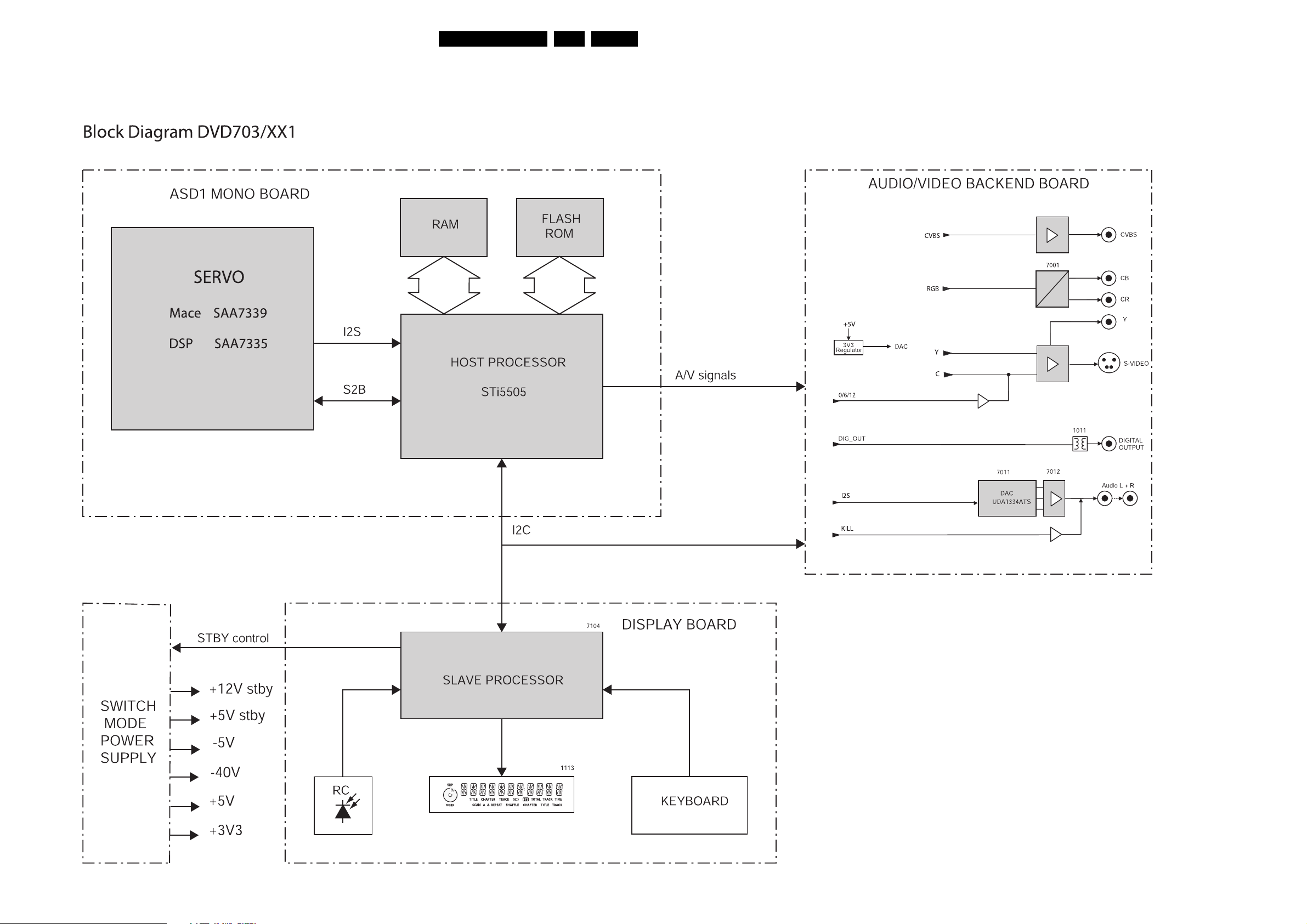
Block- and wiringdiagram.
6. Block- and wiringdiagram.
Blockdiagram DVD 703 /XX!
39DVD703 /XX1 6.
CL 16532007_047.eps
080201
Page 49
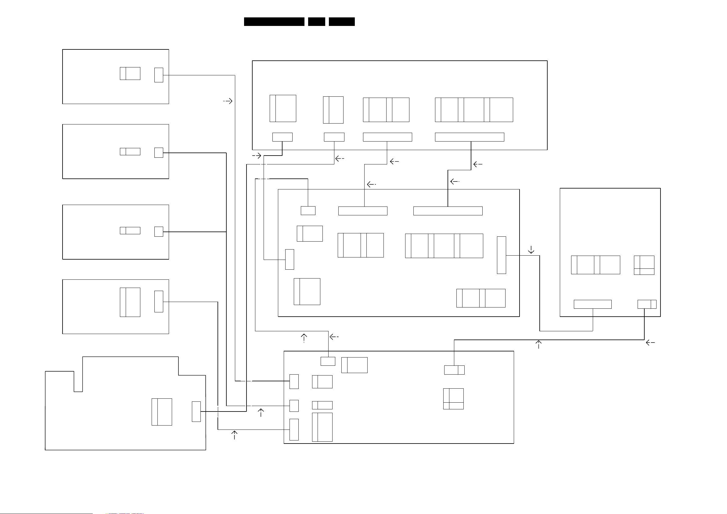
Wiringdiagram
Block- and wiringdiagram.
40DVD703 /XX1 6.
LEAD 2001
STANDBY
1
2
3
4
BOARD
DVD 612 AP
1
SW
2
BOARD
DVD 612/17X
DVD 612/0XX
12STBKEY+
STANDBY
BOARD
1
DVD 870 ONLY
STANDBY
COMBI
2
34+5VSTBY
5
6
7
8
9
BOARD
DVD 733K ONLY
HEADPHONE/MIC
BOARD
+5VSTBY
STBLED
STBKEY+
STBKEY-
MECH SW
MECH SW
STBKEY-
MECH SW
MECH SW
STBKEY+
STBKEY-
AIN12
AIN4
AIN2
AIN1
1117
1206
1205
1201
1
EH
4
3139 110 38631
100MM
1
EH
2
1
EH
2
1
EH
9
140MM
1
GND
ADC_SCLK
2
ADC_LRCLK
3
ADC_DATA
4
ADC_PCMCLK
5
+5V
6
-5V
7
8NC
1
1014
FFC
8
3139 110 35151
(DVD 733K ONLY)
1
FFC
1507
8
1
2
3
4
5
6
7
8
SCL
1
2
GND
SCA
3
STBCONTROL
4
5
P50
GND
ADC_SCLK
ADC_LRCLK
ADC_DATA
ADC_PCMCLK
+5V
-5V
NC
PH
1501
1
HP_L
MIC GND
2
HP_R
3
+5V
4
MIC_A
5
GND
6
-5V
7
KILL
8
1013
81
EH
3139 110 39161
280MM
15
GND
1
H_SYNC
2
GND
3
PCM_OUT2
4
GND
5
PCM_OUT1
6
7
-5V
8
SCL
3104 157 02361(SUB LEAD)
400MM
280MM
3103 308 91151 (LEAD)
A/V BOARD
1
GND
H_SYNC
2
GND
3
4
PCM_OUT2
5
GND
6
PCM_OUT1
-5V
7
8
SCL
16
3104 157 11201 (EU)
FFC
1604
+12VSTBY
9
10
SDA
+6VSTBY
11
12
3V3A
GND
13
14
C
15
GND
Y
16
+12VSTBY
9
SDA
10
+6VSTBY
11
3V3A
12
GND
13
14
C
15
GND
16
Y
1000
FFC
1
3139 110 34231(AP & US)
105MM
130MM
116 122
P50
1
B (U)
2
G (Y)
GND
4
5
R (V)
6
CVBS
GND
7
0|6|12
8
MONO BOARD
10
11
12
13
14
15
16
9
13P50
2
3
4
5
6
7
8
22
B (U)
G (Y)
GND 12
R (V)
CVBS
GND
0|6|12
9
10
11
13
14
15
16
3104 157 11191 (EU)
130MM
FFC
1603
-5V
+5VD
+5WD
KILL
GND
PCM_OUT0
LRCLK
SCLK
17
18
19
20
21
22
1
2
3
4
5
6
-5V
+5VD
+5WD
KILL
GND
PCM_OUT0
LRCLK
SCLK
1010
FFC
17
18
19
20
21
22
GND
PCM_CLK
CENTER_ON
STEREO_MUTE
DIG_OUT
GND
3139 110 33841(AP & US)
140MM
GND
PCM_CLK
CENTER_ON
STEREO_MUTE
DIG_OUT
GND
3V3
3V3
+5V
+5VSTBY
GND
7
8
9
10
11
12
12
1600
1
GND
GND
-5V
STBCONTROL
+12VSTBY+6VSTBY
GND
PH
1
3139 110 34251
3139 110 38931(AP)
280MM
POWER SUPPLY
BOARD
3V3
7
1
3V3
2
+5V
3
4
+5VSTBY
5
+6VSTBY
6
GND
GND
8
GND
-5V
9
STBCONTROL
10
11
+12VSTBY
12
GND
0205
121
PH EH
1
2
3
4
5
6
+12V
GND
+5VSTBY
-40V
MECH SW
MECH SW
0207
41
3139 110 38681
(EU)
280MM
1
15
(LEAD)
(SUB_LEAD)
SCL
2
GND
SCA
3
4
STBCONTROL
5
P50
DISPLAY BOARD
EH
1
1115
1
+12V
GND
2
3
+5VSTBY
4
-40V
56MECH SW
MECH SW
4
6
CL 16532007_037.eps
020201
PH
1
EH
1117
4
1
HP_L
2
MIC GND
HP_R
3
4
+5V
5
MIC_A
GND
6
-5V
7
KILL
8
1200
1
EH
8
3139 110 38371
100MM
3139 110 35610
80MM
1
1117
EH
2
1
1122EH
9
1118
1
+5VSTBY
2
STBLED
STBKEY+
3
STBKEY-
4
12STBKEY+
STBKEY-
MECH SW
1
2
MECH SW
34+5VSTBY
STBKEY+
STBKEY-5
6
AIN12
7
AIN4
8
AIN2
9
AIN1
Page 50
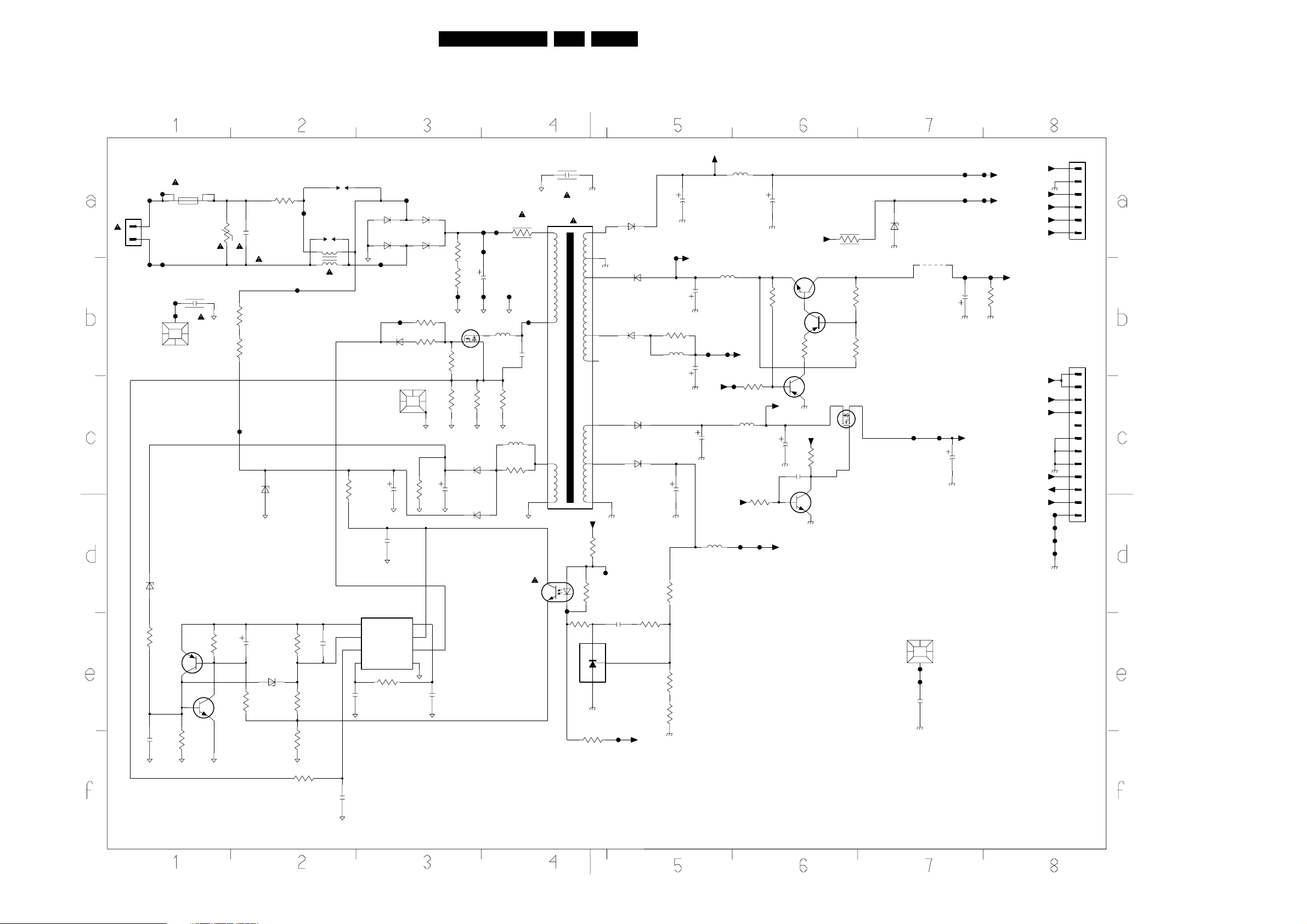
Electrical diagrams and Print-layouts
7. Electrical diagrams and Print-layouts
Power Supply Unit VFM WR (3122 427 22600)
41DVD703 /XX1 7.
0101
F101
2
1
F102
6141
3139
2150
F111
F112
F130
F131
UDZ-18B
47R
BC557B
100n
1120
T2.5A H 250V
0199
7141
3150
2130
1n
1K5
3120
3141
7150
BC547B
6K8
V
2120
27K
27K
3134 3123
F109
2141
BZX284-C4V7
3143
100n
6129
2u2
36K
6150
3122
2R7
F108
UDZ-22B
3145
3153
3154
1121
F120
1122
12
5121
43
CU15D3
18K
4n7
2145
15K
1K5
MECHPART
10R
3111
1
COMP
2
Vfb
3
Isense6OUTPUT
4
RtCt
470p
2157
F104
6120 6121
1N4006
6118 6119
1N4006
F119
F110
6140
1N4148
0125
2134
2143
100n
7145
UC3842A
Vref
VCC
GND
3146
56K
47u
1N4006
1N4006
3140
560R
3156
33R
3137
8
7
5
100K
2146
2135
3131
270K
3136
270K
F116
7125
STP3NB60FP
22K
3125
3R6
3126
BAV21
10u
BAV21
100n
2121
3127
6132
6133
F117F118
F105
100u
F106
1R
3132
F115
5125
83R
1R
3128
5135
27u
3135
15R
TCET1102G
1R
2127
F107
7131
470p
1
5
7
9
5131
CT282D4
F225
2131
1n
3262
220R
+12Va
3201
3207
3203
47R
15
14
11
16
17
12
10
13
1K
1
2
BYW98-200
10R
F224
2202
100n
7201
TL431CZ
3
F227
6241
6250
BYD33D
6261
BYD33J
6230
BYW95C/20
6210
BYW98-200
3204
270R
Off_2
F226
3260
100R
5260
3202
3205
3206
10u
2210
2240
1K8
4K7
390R
Off_1
2250
2260
2m2
470u
2230
+12Va
220u
F208
22u
5210
5222
47u
F209
Standby
1000u
Standby
6u8
5240
1u
-40V
F207
3258
10K
5231
6u8
F214 F215
3235
15K
2232
3254
100u
22K
7256
BC857B
3255
+6Va
2238
7235
BC847
+3V3
100u
2235
33n
7255
+12Va
+6Va
BC337-40
470R
7257
BC857B
1K8
3263
3233
2R2
3256
3257
680R
6K8
7238
IRLML2803
6233
BZX79-C4V7
9259
F212
0299
F230
F231
22n
2299
F213
2239
F201 F202
F204
F203
F205
100u
2259
+5V
100u
F206
3259
+12V
+5Vstby
1K
-5V
+12V
+5Vstby
-40V
Off_1
Off_2
+3V3
+5V
+5Vstby
-5V
Standby
+12V
F220
F221
F222
F223
0209
EH-B
1
2
3
4
5
6
0205
EH-B
1
2
3
4
5
6
7
8
9
10
11
12
3155
330R
2156
330p
CL 16532007_036.eps
020201
Page 51
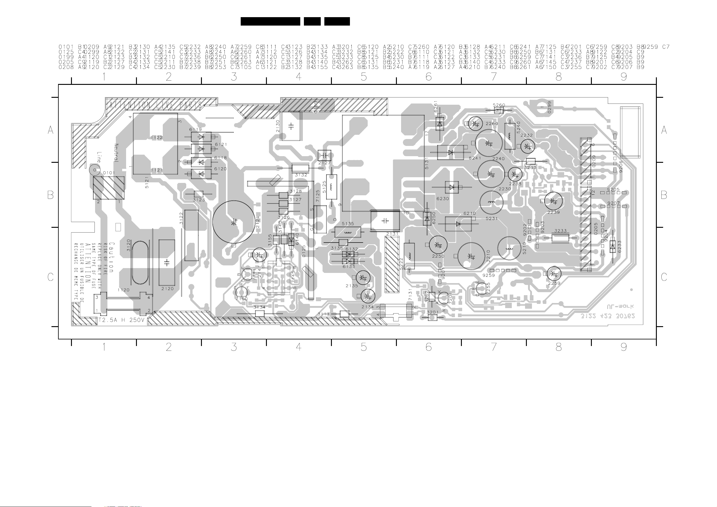
Electrical diagrams and Print-layouts
Layout Power Supply Unit VFM WR (component side)
42DVD703 /XX1 7.
CL 16532007_065.eps
090201
Page 52
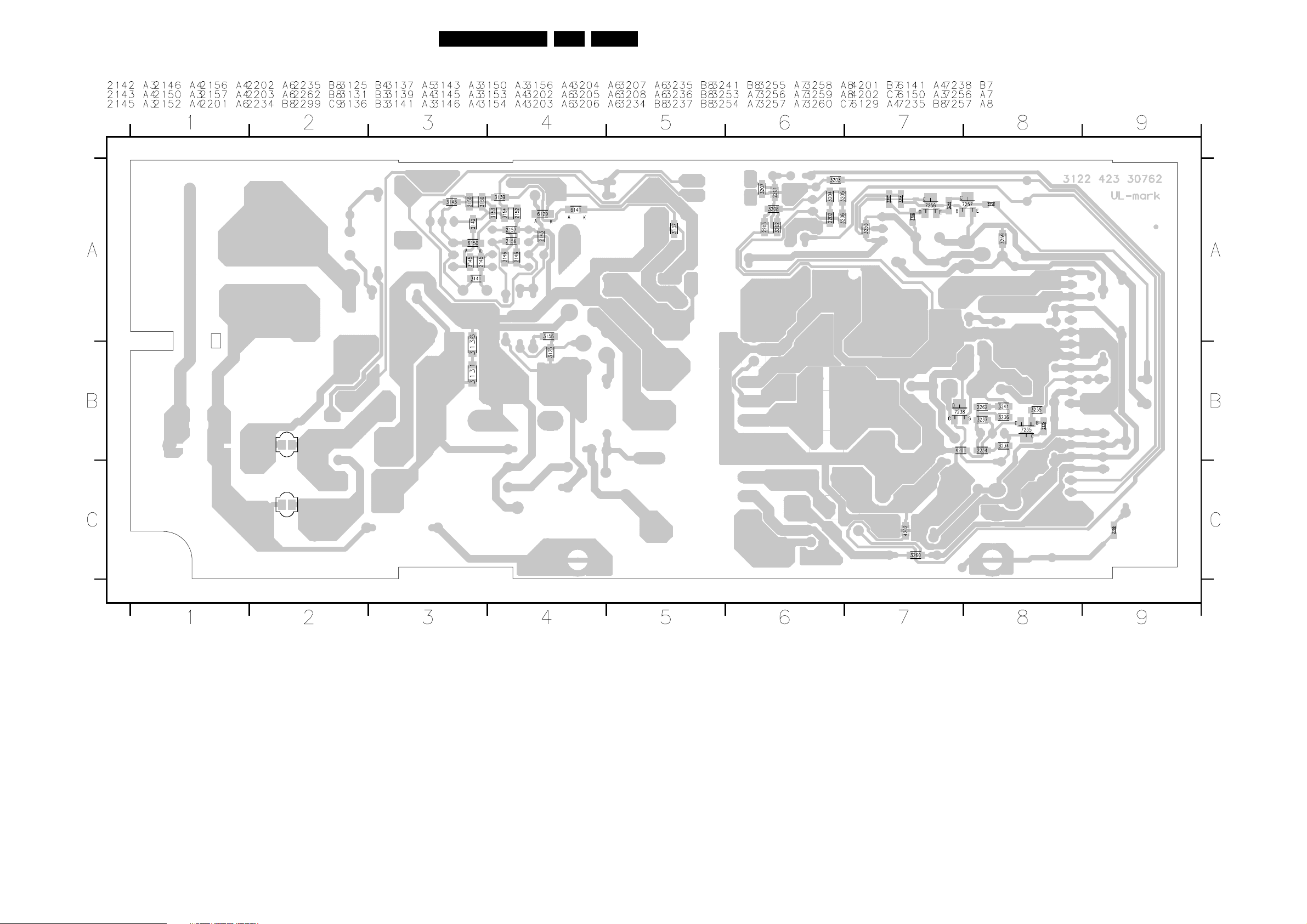
Electrical diagrams and Print-layouts
Layout Power Supply Unit VFM WR (bottom side)
43DVD703 /XX1 7.
CL 16532007_066.eps
090201
Page 53
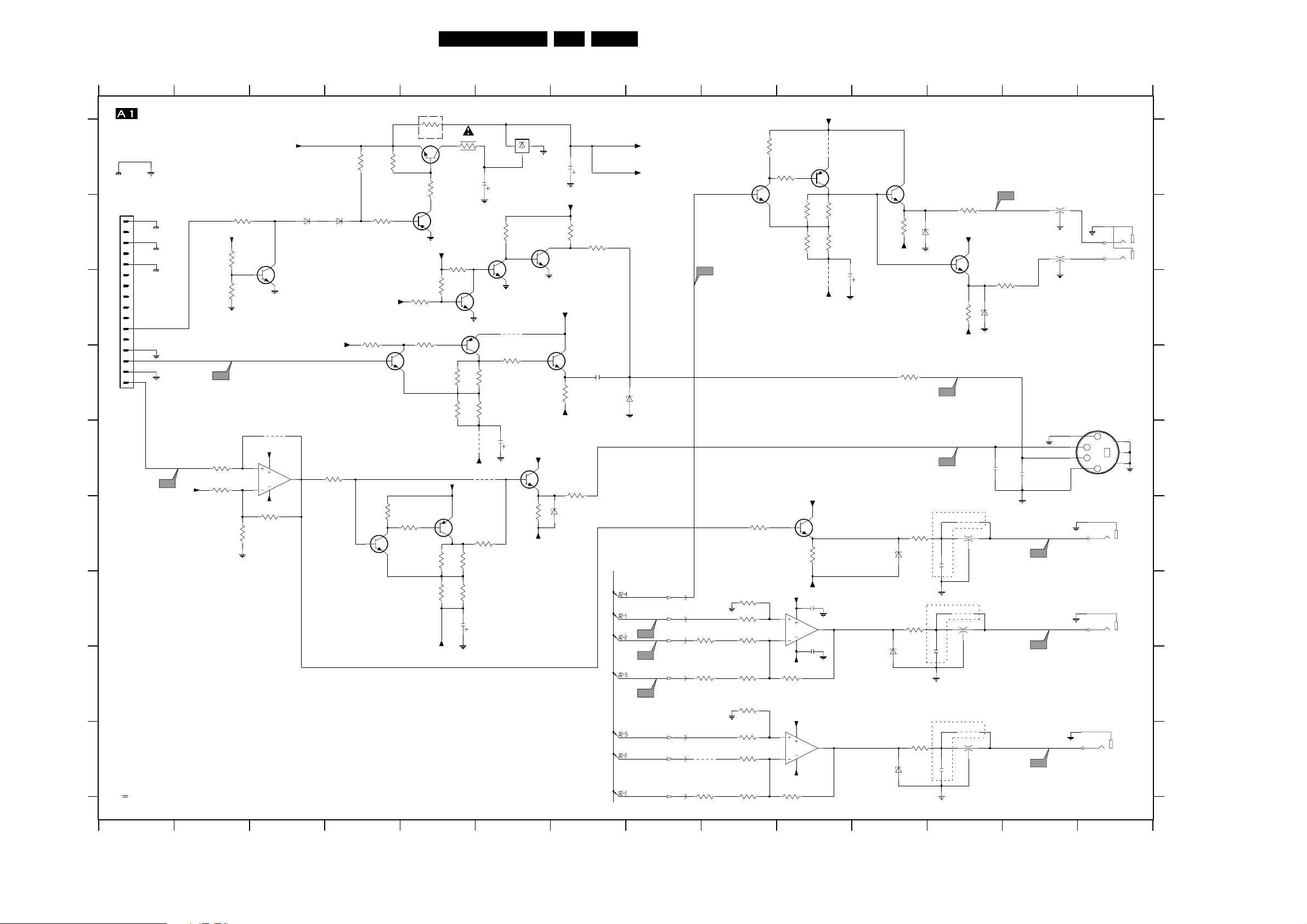
A/V Board (Video control)
1
AV_VIDEO
A
DGND
VGND
1000
FMN
1
2
B
3
4
5
6
7
8
9
C
10
TO MONO BOARD
11
12
13
14
15
16
D
DGND
DGND
DGND
VGND
VGND
E
TP6
F
G
H
I
Reserved Parts
*
V
DC Vtg measured in STOP-MODE
2 3 4 5 6 7 8 9 10 11 12 13 14
Y
-5V
+6Vstby
TP5
3037
100R
3061
6K8
Electrical diagrams and Print-layouts
0V
3001
-9V5
10K
270R
3025
1V5
+5V
3018
3022
-0V3
-0V3
3010
4K7
4K7
2K7
3042
0V7
6K8
-8V
6000
6001
BAS216
BAS216
0V
7400
BC847B
+5VVID
C
4011
*
+5VVID
7001-A
5
4
AD8073
-5V
3041
3K3
7
11
6
1V5
3038
100R
3011
4K7
*
3002
3062
7457
BC847B
-0V7
*
-0V7
-5V
270R
4K7
*
-8V7
3063
100R
3023
10K
7407
BC847B
Option
3028
100R
4000
4R7
3005
7409
BC817-25
4K7
(BC858B)
BC857B
7403
0|6|12
3020
3065
*
3067
*
-5V
-9V4
15K
-2V6
4V2
+5VVID
6K8
4K7
3000
3019
22K
3030
3034
7458
*
BC857B
3066
*
3068
*
100u
4R7
2V
6K8
4K7
0V2
7404
BC847B
3031
3035
-5V
*
820R
680R
2016
*
22u
4V9
BC857B
7408
820R
680R
4006
4010
3064
100R
-9V2
2001
100u
-4V5
OUT
3014
7405
BC847B
4004
3029
100R
7002
MC79L05
2
22K
2008
IN
0V7
GND
2V
+5VVID
0V8
13
-5V
3040
7406
BC847B
7455
BC847B
2K2
1m0
+5VVID
3013
0V
+5VVID
7410
BC847B
1V5
3033
470R
-5V
3039
75R
6003
BZX284-C15
2K2
2002
3017
8K2
2007
470n
44DVD703 /XX1 7.
1000 B1
1003 E14
1006-A F14
1006-B G14
+5VVID
-5V
3003
270R
-5VA
4V2
0V3
1V
TP4
6002
BZX284-C15
Yout
CVBS
VGND
3049
10R
3051
750R
VGND
9102
3058
560R
TP1
TP2
TP3
B
G
R
R
G
B
3046
1K
3047
1K
3050
1K5
3052
2K2
3054
1K
3055
1K
3057
1K2
3059
5K6
3043
100R
-0V3
3004
100R
7411
BC847B
1V5
12
13
-0V3
-0V3
10
9
-0V3
+5VVID
3053
1K
+5VVID
3060
1K
4V2
4
11
-5V
4
11
-5v
3006
3015
+5VVID
3045
-5V
2012
22n
2013
22n
7001-B
AD8073
6K8
3007
4K7
3016
-5V
7415
BC847B
0V8
2K2
14
8
0R
4001
4V9
BC857B
7412
1V5
4003
VGND
7001-C
AD 8073
820R
680R
0V
7413
BC847B
0V8
2K2
3012
6008
BZX284-C15
-5V
2004
100u
3032
75R
3044
75R
6005
BZX284-C15
Uout
0V
Vout
3048
75R
6006
BZX284-C15
VGND
3056
75R
6007
BZX284-C15
1V5
TP15
TP16
OPTION
2011
220p
VGND
OPTION
13
220p
2014
OPTION
2015
220p
VGND
3009
75R
+5VVID
3024
-5V
4007
13
4008
2
4009
13
7414
BC847B
0V8
2K2
5006
DSS306
5007
DSS306
2
6004
BZX284-C15
2009
5005
DSS3062
TP14
3021
75R
220p
2010
220p
TP17
TP18
TP19
DSS306
5004
DSS306
VGND
5003
VGND
VGND
VIDEO
13
1008-A
YKC21-4040
2
2
2
3
13
1
S-VIDEO
1003
TCS79
1
3
4
2
1006-A
2
YKC21-4104
1
1006-B
4
YKC21-4104
3
1006-C
YKC21-4104
6
5
BARE BOARD PCB
3139 243 30160
CL 16532007_011.eps
5
7
6
Y
U
V
130201
1006-C I14
1008-A B14
2001 A6
2002 A7
2004 C11
2007 D7
2008 E6
2009 E12
A
2010 E13
2011 F12
2012 G10
2013 H10
2014 H12
2015 I12
2016 G5
3000 A5
3001 A4
3002 A4
3003 A9
3004 A10
B
3005 A5
3006 B10
3007 B10
3009 B12
3010 B2
3011 B4
3012 B11
3013 B7
3014 B6
3015 B10
3016 B10
3017 B7
C
3018 B2
3019 B5
3020 C5
3021 C13
3022 C2
3023 C5
3024 C12
3025 D4
3028 C5
3029 D6
3030 D5
D
3031 D6
3032 D11
3033 D7
3034 D5
3035 D6
3037 E2
3038 E4
3039 E7
3040 F6
3041 F3
3042 F2
3043 F9
E
3044 F11
3045 F10
3046 G9
3047 G9
3048 G11
3049 G9
3050 G9
3051 H9
3052 H9
3053 H10
3054 H9
3055 I9
F
3056 I11
3057 I9
3058 I9
3059 I9
3060 I10
3061 E2
3062 F4
3063 F5
3064 F6
3065 F5
3066 F5
G
3067 G5
3068 G5
4000 A5
4001 A10
4003 C10
4004 C6
4006 E6
4007 F12
4008 G12
4009 I12
4010 E6
4011 E3
H
5003 B13
5004 B13
5005 F12
5006 G12
5007 I12
6000 B3
6001 B4
6002 D8
6003 F7
6004 C12
6005 F11
6006 H11
I
6007 I11
6008 B12
7001-A E3
7001-B I10
7001-C G10
7002 A6
7400 C3
7403 B5
1 2 3 4 5 6 7 8 9 10 11 12 13
14
Page 54
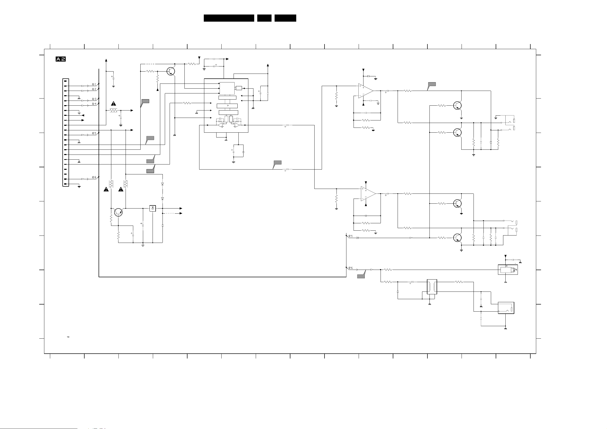
A/V Board (Sound)
Electrical diagrams and Print-layouts
45DVD703 /XX1 7.
1234567891011121314
*
3205
47R
+3V3_A
+3V3_D
+3V3_D
3200
1K
1V1
2V5
2V5
1V6
AV-SOUND
TO MONO BOARD
1001
1
2
3
4
5
6
7
8
9
10
11
12
13
14
15
16
17
18
19
20
21
22
DGND
CVBS
KILL
DGND
DGND
DIG_OUT
B
G
R
0|6|12
-8V
A
B
C
D
E
+5VVID
4R7
3230
2204
3202
4R7
3229
BC817-25
4K7
100u
7456
3231
2200
4R7
100K
100u
+5VA
+5V
PCM_OUT0
LRCLK
SCLK
PCM_CLK
3213
*
4V8
2231
470u
2216
*
TP8
10u
4200
3201
2K2
*
TP7
TP9
TP10
7010
LF33CV
IN OUT
GND
3232
-5V
10K
6201
6202
2217
1SS355
1SS355
4201
470n
*
7450
PMST222A
DGND
F
G
H
Reserved Parts
*
2207
7011
UDA1334TS
1
BCK
2
WS
3
DATA I
6 SYSCLK|PLL1
MUTE8
DGND
9 DEEM|CLKO
14
VOL
100n
2208
47u
VDDA4VDDD
INTERFACE
DE-EMPHASIS
INTERPOLATION
NOISE SHAPER
VSSA5VSSD
15
+3V3_A
13
DIGITAL
DAC
DGND
FILTER
DAC
VREF-DAC
2210
PLL
47u
+3V3_D
+5VA
2201
100n
PLL0
10
11SFOR0
7SFOR1
16
VOR
12
1V6
2211
100n
DGND
1V6
2205
100u
100n
2206
TP12
2202
10u
2214
10u
0V
10K
3227
0V
10K
3228
BARE BOARD PCB
3139 243 30160
0V
0V
7012-A
3
8
LM833D
2
4
2209
100n
-5VA
2229
100p
3208
8K2
3210
4K7
+5VA
7012-B
5
LM833D
8
6
4
-5VA
2230
100p
3216
8K2
3218
4K7
DIG_OUT
TP11
1
OV1
OV1
2203
100u
2215
7
100u
3224
100R
3225
100R
ST_L
ST_R
2226
3203
680R
3207
680R
3214
680R
3219
680R
KILL
2225
10u
47p
TP13
3206
2K7
3209
2K7
3215
2K7
3220
2K7
5008
920927152B
34
2
1
6
78
OV7
OV7
OV7
OV7
7454
BC817-25
0V
3226
68R
0V
7451
BC817-25
7452
BC817-25
0V
7453
BC817-25
0V
3211
3221
10K
10K
2212
2227
2228
2221
1n
100n
47p
RIGHT
1008-C
YKC21-4040
8
9
7
1n
10K
2213
3212
LEFT
1008-B
YKC21-4040
4
6
2222
5
1n
1n
10K
3222
OPTICAL
+5V
2224
100n
2
1
DRIVER
3
7028
GP1F32T
DIGITAL
1011
YKC21-3416
3
2
1
1001 A1
1008-B E14
1008-C B14
1011 G14
2200 B2
2201 A10
2202 B7
2203 A10
2204 A2
2205 A7
2206 A7
2207 A5
A
2208 A5
2209 B10
2210 C6
2211 C6
2212 C13
2213 C13
2214 C7
2215 D10
2216 E3
2217 E4
2221 F13
2222 E14
2224 F14
B
2225 G11
2226 G11
2227 G13
2228 H13
2229 B10
2230 E10
2231 E3
3200 A5
3201 A3
3202 B2
3203 A11
3205 B4
C
3206 B12
3207 B11
3208 B10
3209 B12
3210 B10
3211 C13
3212 C14
3213 D3
3214 D11
3215 E12
3216 E10
3218 E10
D
3219 E11
3220 F12
3221 F13
3222 F13
3224 F10
3225 G10
3226 G12
3227 A9
3228 D9
3229 D2
3230 E2
E
3231 E2
3232 A4
4200 A3
4201 E4
5008 G11
6201 D4
6202 D4
7010 E3
7011 A5
7012-A A10
7012-B D10
7028 G14
F
7450 A4
7451 B13
7452 B13
7453 E13
7454 F12
7456 D3
G
H
V
DC Vtg measured in STOP-MODE
1
234567891011121314
BARE BOARD PCB
3139 243 30160
CL 16532007_013.eps
130201
Page 55
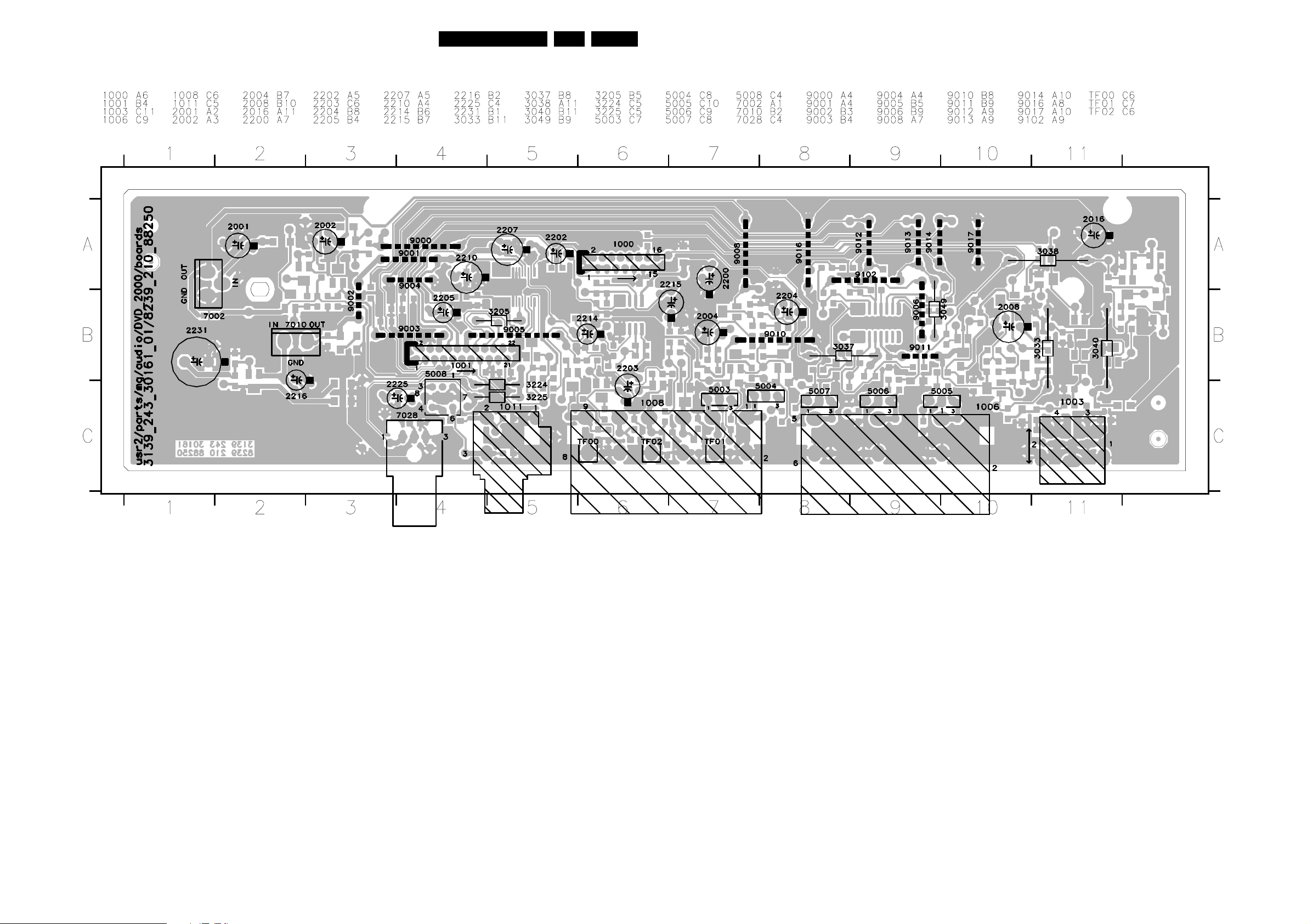
Electrical diagrams and Print-layouts
Layout A/V Board (component side)
46DVD703 /XX1 7.
CL 16532007_063.eps
090201
Page 56
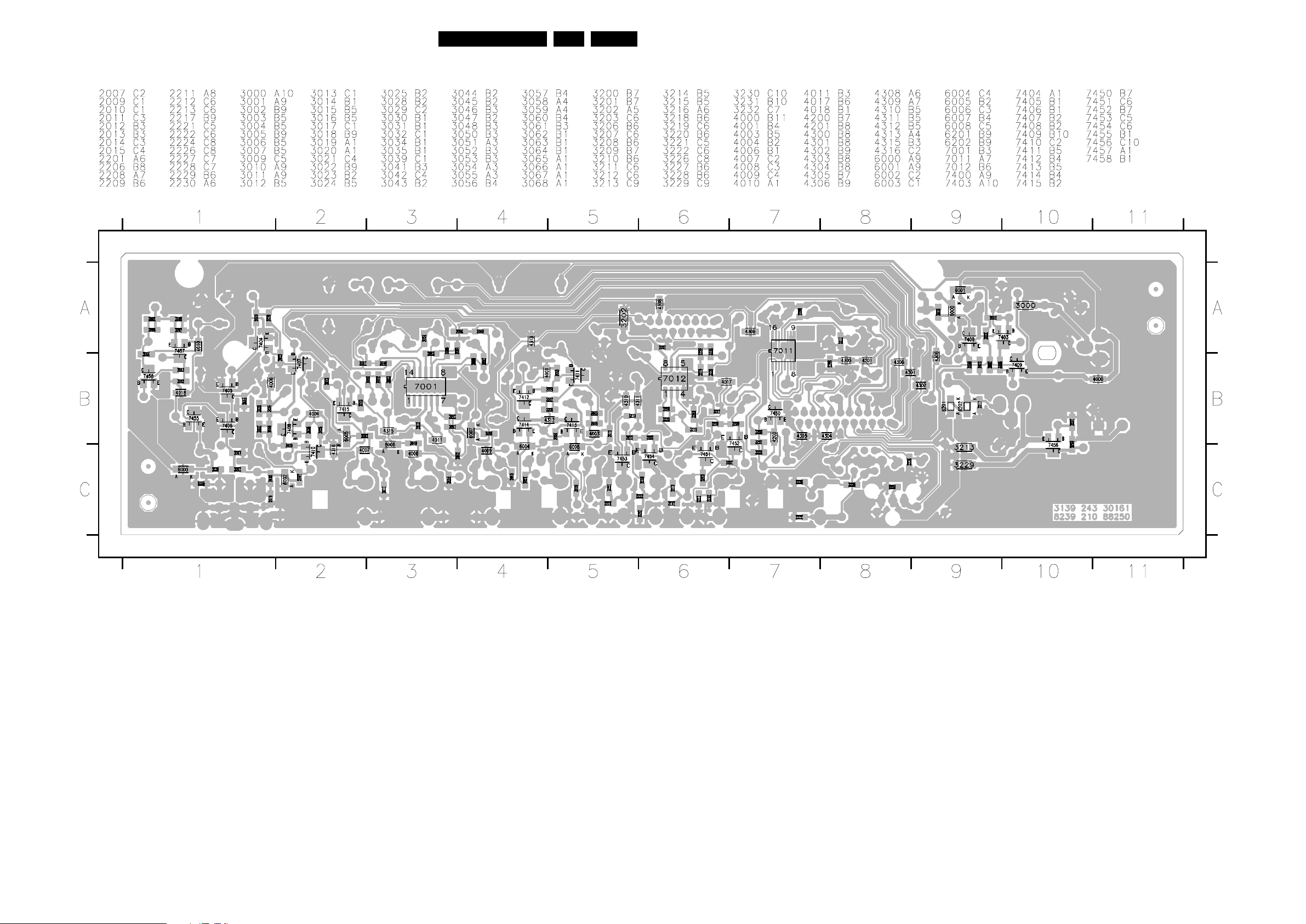
A/V Board (bottom side)
Electrical diagrams and Print-layouts
47DVD703 /XX1 7.
CL 16532007_064.eps
090201
Page 57
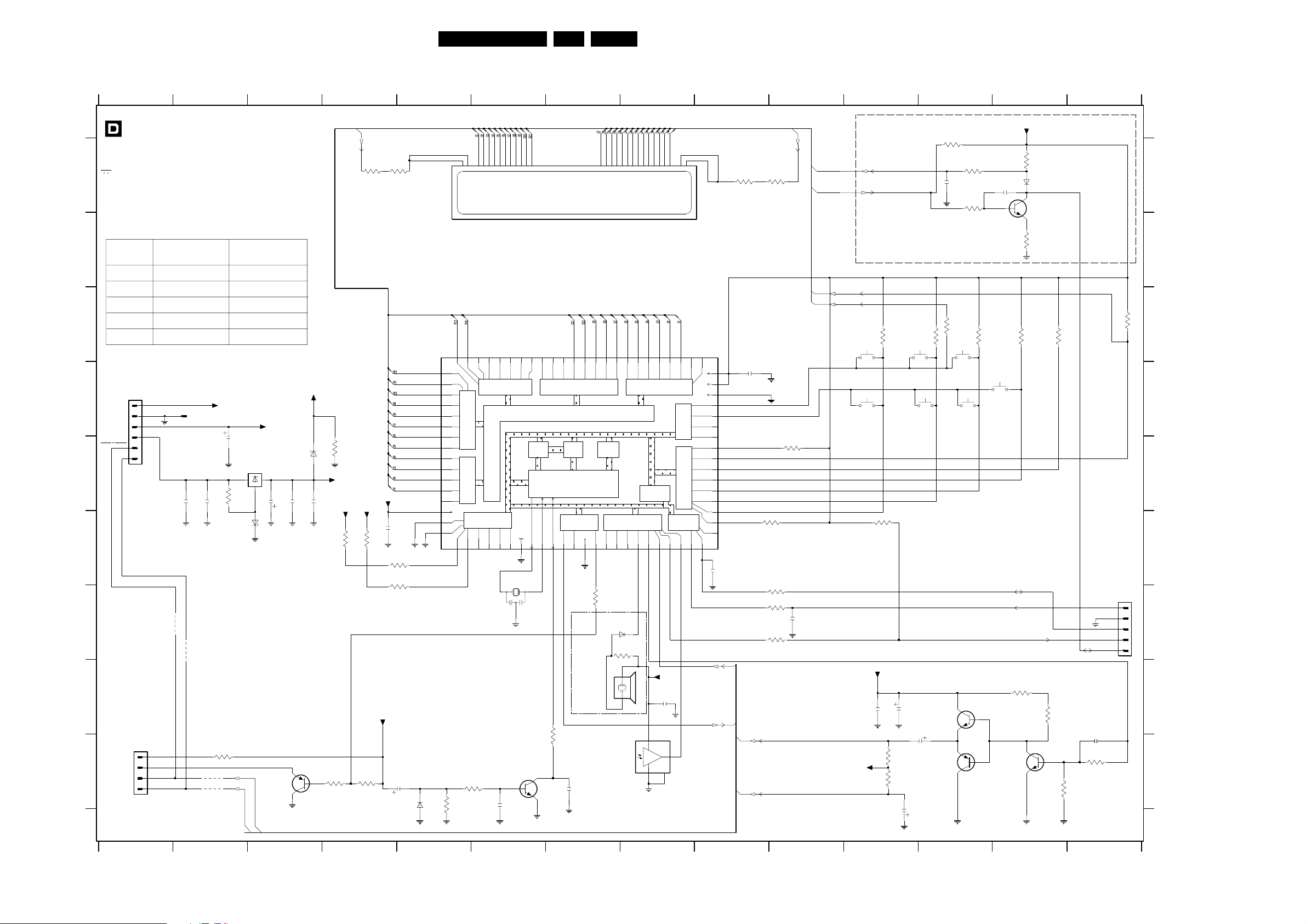
Electrical diagrams and Print-layouts
Display board
123
DISPLAY PANEL
V DC vtg measured in STOP-MODE
A
Diversity table for all items no marked with #
B
ITEM
1115
3155
3156
C
3157
3158
Model using
Mech SW
6P conn
-- Jumper
-Jumper
Jumper
TO PSU
1115
D
E
#
+12V
GND
+5V stb
-40V
1
1001
2
3
4
5
6
RT-01T
-40 V
2108
F
G
3158
#
3157
#
H
EH-B
1117
1
I
2
3
4
TO STANDBY PCB
1205
3155
#
3156
#
123456
33n
+12V
2109
PDZ-8.2B
3135
220R
Model using
Tact SW
4P conn
Jumper
2106
100u
7112
MC79L24
IN2OUT
GND
3119
3
10K
6102
STBKEY+
STBKEY-
D-1
D-2
--
--
+5Vstb
1
2130
22u
VFIL_DC
PDZ-6.2B
3V8
6101
2110
33n33n
BC857B
7109
-32V
5V
2111
33n
45
D-4
FIL2
3103
3105
4R7
2R2
INFO : FIL1 - FIL2
= 3.5 Vac RMS
7104
TMP87CH74
3142
330R
3118
10K
VKK
+5Vstb
3146
+5Vstb
3137
10K
-17V
-27V
-27V
-24V
-32V
-30V
-30V
3147
10K10K
-30V
-30V
-30V
-27V
-17V
VKK
+5Vstb
2107
33n
3148
100R
3149
100R
STBY - LEDCONTROL
2126
10u
6104
BAS216
65
66
67
68
69
70
71
72
73
74
75
76
77
78
79
-SCK1
80
MICRO+
MICRO-
-30V
V23
V24
V25
V26
V27
V28
V29
V30
V31
V32
V33
V34
V35
V36
VKK
SI1
SO1
1
5V
3144
100K
-22V
61 56
62
6364
V22
V21
V20
8-Bit h.break. v.
out w. latch
P9
down
80k pull
8-Bit h. breakdown v.
out. port w. latch
source open
drain 80k p.d.
5-Bit h. breakd. v.
out w. latch PD
8-Bit Input/Output
(tri-state)
P04
P05
P03
3
2
0V
3140
10K
48DVD703 /XX1 7.
6 7 8 9 10 11 12 13 14
2101
220p
0V
1109
SOUND
0V
3132
330R
4V6
7107
BC847B
+5Vstb
5V
4K7
3101
27K
6100
BAS216
7101
BC847B
3106
220R
3115
SCA
SCL
5V4
3134
330R
3113
4K7
P50
3143
10K
3334353637383940414445 56789212223242526272829303132
57
59
58
60
V19
V18
V17
80k pull down
VFT driver circuit (automatic display)
55
V16
V15
V14
8-Bit high breakdown voltage
output part ewith latch
P8
RAM
P0
P07
6
2128
1n
1110
0V
XIN
VSS
10 18 23
7
XOUT
8
94
-RESET
5V
2V
1V6
5V
7108
BC847B
P06
5
11-MT-126GNK
1113
-30V
-30V
52
53 50
54
V13
V12
V11
80k pull down
P6-P9 source open drain
ROM
CPU
sink open
3-Bit In/Output
with latch
XTIN
TEST
12
11
13
XTOUT
0V
3136
1K
2201
33n
-30V
-30V
51
V9
V10
P7
Program
Counter
drain
8-Bit Input/Output
P2
(tri-state)
-INT0
15
14
-STOP
5V
3133
10R
For EUROPE MODELS
1112
PKM
GP1U28XP
-30V
-30V
-30V
-30V
-30V
47
48
49
V7V6V5V4V3V2V1
V8
TC2
-INT1
16
45
46
8-Bit high breakdown v.
output port with latch
80k pull down
8-Bit A/D
Converter
P0
TC4
TC1
-DV0
17
20
19
5V
0V
2V4
only
BAS216
6105
3150
4K7
2116
2
7110
VSUP
GND3MT
-30V
44
3-B. I/O P3
sink o.drain
INT2
21
0V
+5Vstb
33n
OUT 1
4
110111213141516171819 220
-30V
43
42
V0
P6
P5
(tri-state)
4-Bit In/Output
P4
8-Bit Input/Output
(tri-state)
SCL
SCA
INT4
22
5V
5V
5V
-34V-34V
41
VDD
VAREF
VASS
AIN13
AIN12
AIN11
AIN10
AIN7
AIN6
AIN5
AIN4
AIN3
AIN2
AIN1
AIN0
SCK0
24
IN_P50
OUT_P50
40
39
32
30
29
28
27
26
25
2115
22p
D-5
38
37
36
35
34
33
31
D-6
D-3
FIL1
D-6
3107
4R7
3108
2R2
IN_P50
D-5
OUT_P50
D-1
D-2
2105
5V
33n
0V
STBKEY-
STBKEY+
1100
Next
1106
3110
4K7
0V
PLAY
5V
5V
3159
4K7
5V
5V
5V
5V
5V
D-3
D-4
3123
10K
FIL1
FIL2
3122
10R
3125
10R
3130
10R
22p
2114
5V
VFIL_DC
+12V
3121
4K7
2122
33n
3138
470R
3120
470R
2123
100u
2129
22u
4K7
1101
PREV
1107
PAUSE
2124
22u
3111
3100
22K
2100
220p
P50
interface
to scart
3114
10R
OPEN / CLOSE
7105
BC337-25
BC327-25
7106
1102
1108
STOP
12V5
5V5
3102
47K
3104
100K
STBY control
4V6
3112
4K7
4V6
For models with P50 only
7 8 9 1011121314
scart PIN 10
P50
4K7
TO MONO
BOARD
PH-B
1118
1
2
3
4
5
2125
22p
3139
4K7
BARE BOARD PCB
3139 243 30270
CL 16532007_023.eps
130201
3109
F143 A12
1001 D2
F144 A12
1100 C11
F145 G8
1101 C12
F146 D3
1102 C12
F147 E3
1106 D11
F148 D1
1107 D12
F149 D5
1108 D12
F150 E5
1109 D13
F151 E5
1110 G6
F152 E9
1112 H7
F153 C5
1113 A7
F154 E5
1115 D1
F155 E9
1117 I1
F156 E5
1118 G14
A
B
C
D
E
F
G
H
I
2100 A12
2101 A13
2105 D9
2106 D2
2107 F4
2108 E2
2109 E2
2110 E3
2111 E4
2114 G10
2115 F9
2116 H8
2122 H11
2123 H11
2124 I12
2125 I14
2126 I5
2128 I6
2129 I11
2130 E3
2201 I7
3100 A12
3101 A13
3102 A12
3103 A4
3104 A12
3105 A5
3106 B13
3107 A9
3108 A10
3109 C14
3110 C11
3111 C12
3112 C12
3113 C14
3114 C12
3115 C13
3118 E4
3119 E2
3120 I11
3121 F11
3122 G10
3123 F10
3125 G10
3130 G10
3132 H13
3133 G7
3134 H13
3135 I2
3136 H7
3137 I4
3138 I11
3139 I14
3140 I6
3142 I4
3143 I14
3144 I5
3146 F4
3147 F4
3148 F5
3149 F5
3150 G8
3155 I2
3156 I2
3157 G2
3158 G2
3159 E10
6100 A13
6101 E3
6102 F2
6104 I5
6105 G8
7101 A13
7104 C5
7105 H12
7106 I12
7107 I13
7108 I6
7109 I3
7110 I8
7112 E3
F102 D5
F103 D5
F108 A5
F109 A9
F119 C7
F120 C7
F121 C7
F122 C8
F123 C8
F124 C8
F125 C5
F129 C7
F130 C7
F131 C7
F132 C8
F133 C8
F137 D5
F138 D5
F139 D5
F140 H8
F141 D5
F142 D9
F157 E9
F158 E5
F159 E9
F160 E9
F161 E9
F162 I6
F163 I7
F164 H6
F165 A13
F166 A13
F167 B13
F168 F1
F169 F1
F183 I1
F184 I1
F186 E9
F203 D2
F205 E1
F208 G13
F209 G13
F210 G13
F228 D1
F233 D9
F234 I1
F235 I1
F241 G14
F242 G14
Page 58
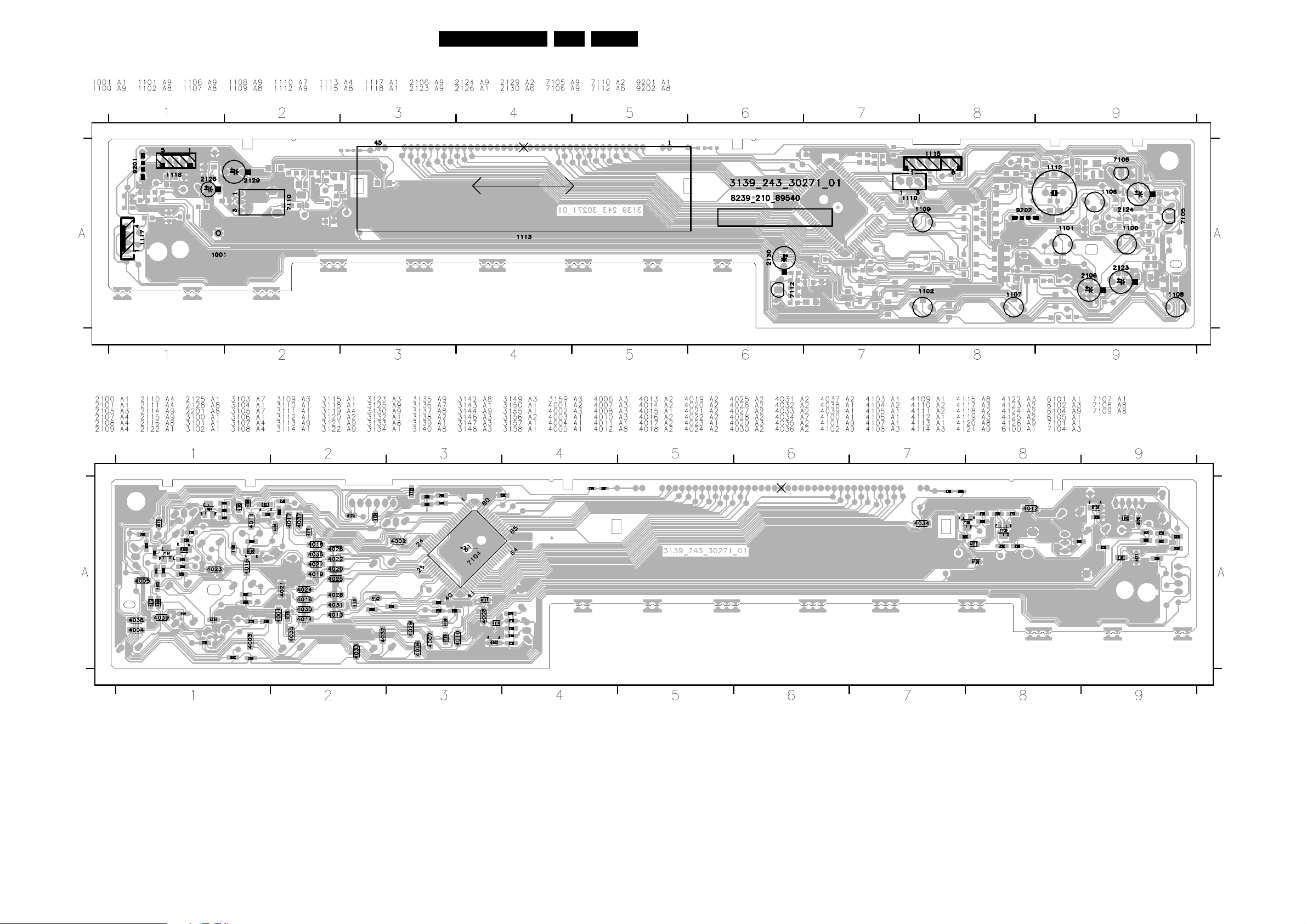
Electrical diagrams and Print-layouts
Layout Display Board (component side)
49DVD703 /XX1 7.
Layout Display Board (bottom side)
CL 16532007_067.eps
090201
CL 16532007_068.eps
090201
Page 59
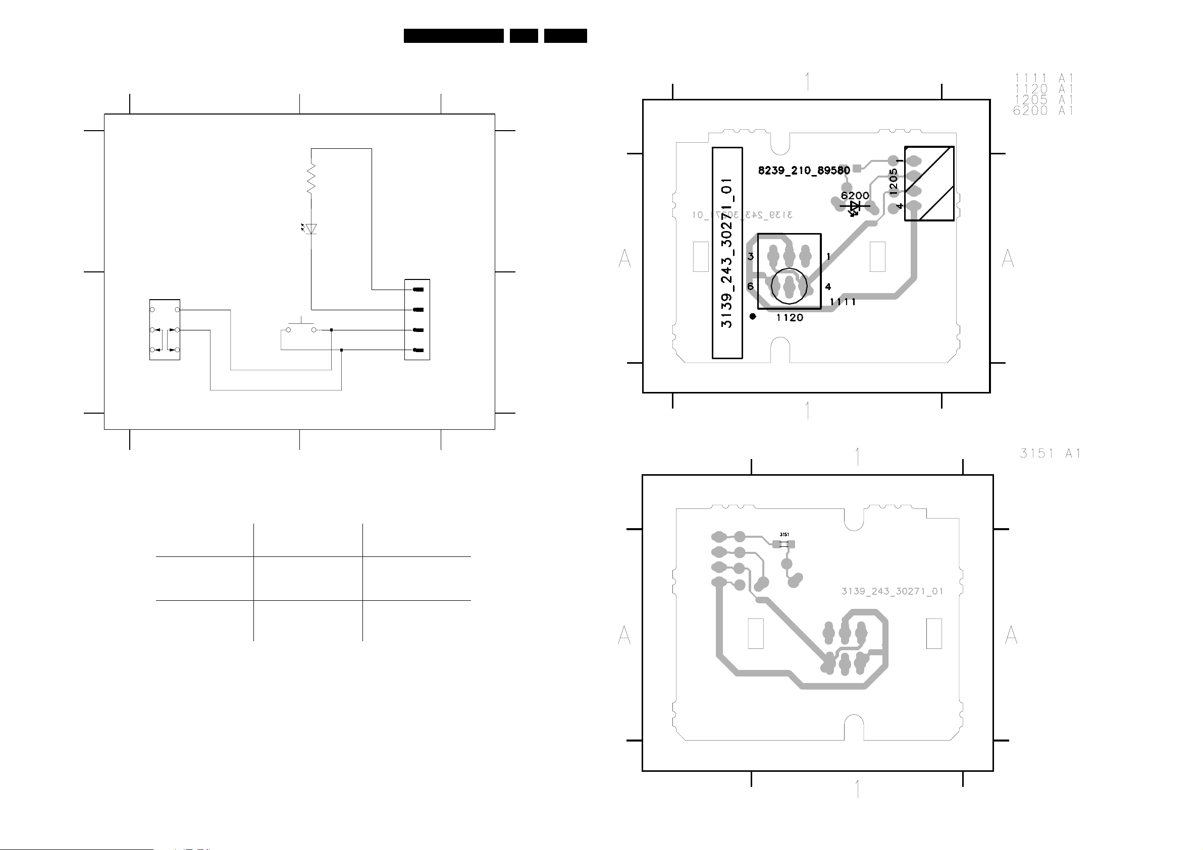
Electrical diagrams and Print-layouts
50DVD703 /XX1 7.
Bare board Standby
A
#
1120
6
5
B
4
12
3151
100R
6200
LTL-1CHPE
BOARDTO DISPLAY
1205
1
3
2
1
STANDBY
1111
#
2
3
4
EH-S
STBKEY+
STBKEY-
A
B
Layout Bare board Standby (component side)
1111 B1
1120 B1
1205 B2
3151 A1
6200 A1
F236 A2
F237 A1
F238 B1
F239 B2
F240 B2
SPEC12
DIVERSITY
#
1120
1111
1
MODEL USING
MECH SWITCH SW
YES
BARE BOARD PCB
3139 243 30270
CL 16532007_025.eps
2
MODEL USING
TACT SWITCH SW
YES
130201
Layout Bare board Standby (component side)
CL 16532007_026.eps
020201
CL 16532007_027.eps
090201
 Loading...