

Page 1
Super VGA Color
Display
installation and
OPERATION GUIDE
Model
CM2089
Page 2

Page 3

CM2089
Super VGA Color Display
English Operating Instructions
For Customer Use:
Enter below the Serial No. which is located on the
back of the cabinet. Retain this information for
future reference.
Model No. CM2089
Serial No.
A
CAUTION TO REDUCE THE RiSK OF EiECTR.C SHOCK DO NOT REf/OVE COV£R(OR BACK)
NO USER SERVICEABLE PA5HS LNS'DE REFER SERVICING TO QUALIFIED SERVICE PERSON.NEL
______________________
CAUTION
RISK OF FLECTRICAL SHOCK
DO NOT OPEN
ATTENTION
RISQUE DE CHOC ELECTRIQUE
NE PAS OUVRIR
...............
A
2-12
This "bolt of lightning" indicates that uninsulated material within your
A
remove product covering.
A
maintenance problems.
unit may cause an electrical shock. For the safety of everyone, do not
This "exclamation point" calls attention to a feature for which you should
read the enclosed literature carefully to prevent operating and
Page 4

2 introduction
Thank you for your patronage. This Super VGA Color Display is designed
for use with IBM PS/2 PCs (Personal Computers) and compatibles that
can utilize the Video Graphics Array (VGA) standard. Typical examples
are IBM compatible PC, PC/AT, 386, 386SX, 486, 486SX, and Personal
System 2 (PS/2).
The Magnavox CM2089 is a tri-scan, high resolution color monitor capable
of displaying VGA, SVGA (VESA/56) and XGA (interlaced) video modes.
This monitor has a maximum resolution of 1024x768 (interlaced) when
driven by graphics adapters supporting IBM XGA, 8514/A, or interlaced
EVGA modes at a 35.5 KHz horizontal scanning frequency.
IMPORTANT - Only horizontal scan frequencies of 31.5 KHz, 35.2 KHz
and 35.5 KHz are supported.
IBM, IBM PC, PC/XT, PC/AT, Personal System 2, PS/2, XGA, 8514/A
and Video Graphics Array (VGA) are registered trademarks of International
Business Machines Corporation. 386,386SX, 486, and 486SX are registered
trademarks of Intel Corporation.
Page 5
Installation
Please be stire the AC (Alternating Cirrrent) power of your computer is
"OFF" before connecting or disconnecting any display peripheral.
Failure to do so may cause serious personal injury as well as permanent
damage to your computer equipments.
NOTE:
Before installing this monitor, please refer to both your computer and
video-graphics-card user's guides to make sure if these pieces of
equipment require any change of setting.
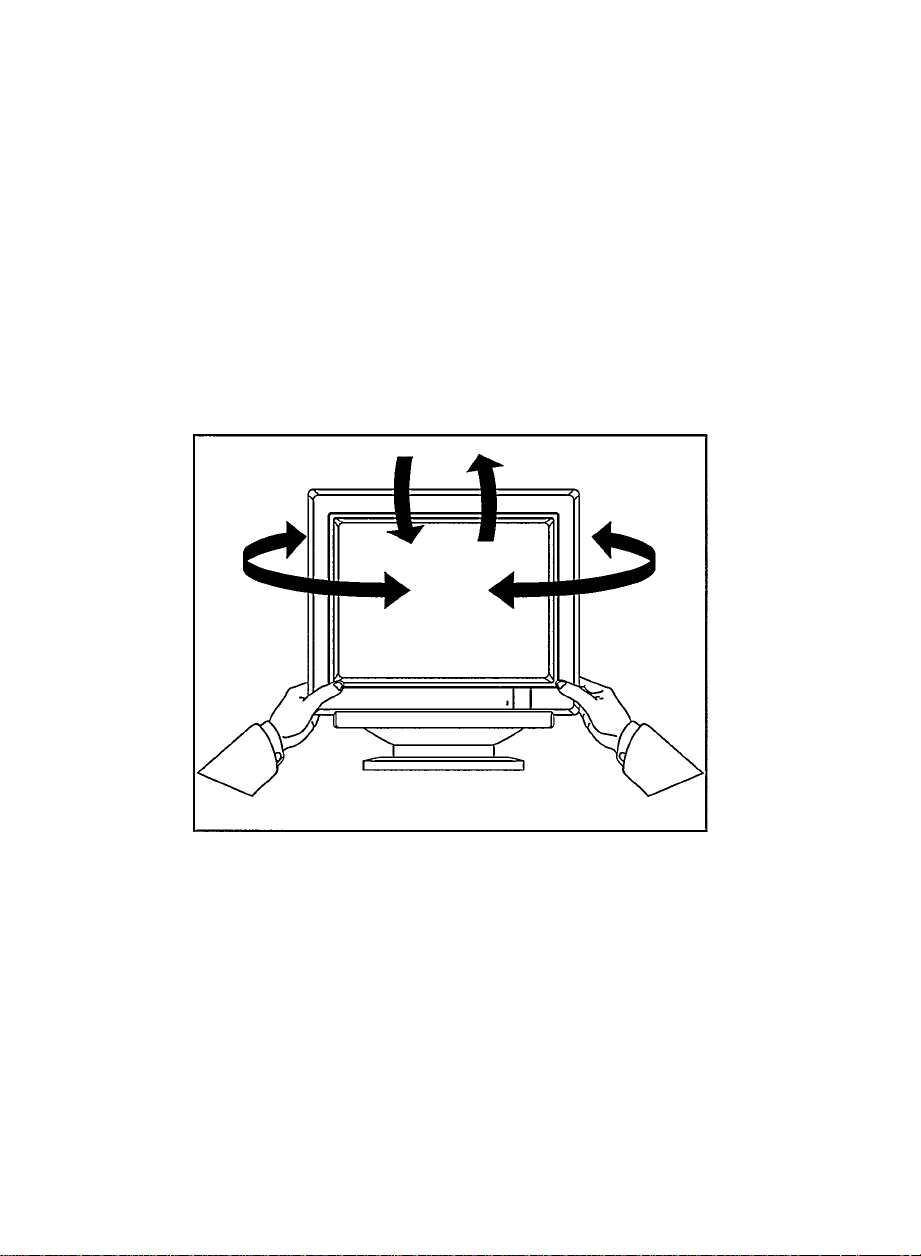
Pedestal
The pedestal enables you to place the monitor into a convenientposition with
best viewing comfort by tilting and/or turning the monitor.
To install the pedestal, refer to the illustration on the inside back-cover of this
manual.
Page 6
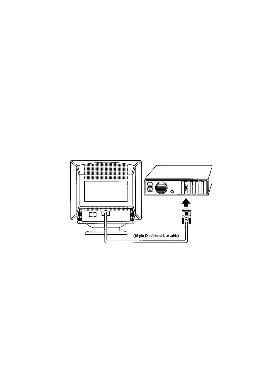
4 Connection to the computer
IBM PC, PC/XT, PC/AT, PS/2, or the compatibles:
• Connect the fixed 15-pin D-sub connector of the video signal
cable to the computer at the video connector on the video card,
and fix it firmly with the screws on the plug.
Page 7

Connecting Power
(Rear of the monitor)
Connecting Powen
The power cord in use must be shielded. Plug one end of the power cord
into the power socket in the rear of tihe monitor, then plug the other end
into any standard 3 wire AC (100/120V) AC outlet.
Page 8

Operational Adjustment
For an optimized adjustinent of the picture following controls are available
at the front.
® POWER
•Press this knob, the green LED lights and power is ON.
•Press this knob again, the green LED disappears and the
power is OFF.
3 CONTR.
• Used to adjust contrast.
-jii- BRIGHT.
• Used to adjust brightness.
S H-SIZE
• Used to adjust image width.
OH-SHIFT
• Used to adjust image position horizontally.
CD V-SIZE
• Used to adjust image height.
0 V-SHIFT
• Used to adjust image position vertically.
Page 9

Operational Adjustment
The monitor is pre-set on 800x600 mode as default SVGA Mode. For
an alternative mode, i.e. 1024x768, the following controls are available
at the rear to optimize adjustment of the picture: (The default mode
will be replaced by re-adjust pre-set)
0 H-SIZE
• Used to adjust image width.
CD H-SHIFT
• Used to adjust image position horizontally.
CD V-SIZE
• Used to adjust image height.
S V-SHEFT
• Used to adjust image position vertically.
Page 10

8
A. Do not place objects on top of the monitor cabinet which could fall
into vents, or which could cover them and prevent proper cooling of
the monitor's electronics.
B. To reduce the risk of fire or shock, never expose the monitor to rain or
excessive moisture.
C. Do not place your monitor where sunlight or bright room light will
fall directly on the screen.
D. When necessary, clean the cabinet with a damp cloth. Use only mild
detegrents. Do not use alcohol or ammonia-base products.
E. Unplug the AC (Alternating Ciuxent) cord for the outlet if the
monitor is not to be used for an extended period of time.
F. Do not attempt to move this monitor by yourself. It weights over 24
lbs(ll Kg). Also, do not place this monitor on top of your computer.
User Maintenance Caution
There are no user serviceable'parts inside the monitor's cabinet. Do not
attempt to remove the cabinet back, as you will be exposed to a shock
hazard.
Safety Precautions
Package
After impacking the shipping carton, check if you have received the
following items:
1. Monitor
2. AC Power Cord
3. IB6770E-1
4. Registration Cards EL4355-2 for USA and EL4438-2 for Canada
5. Factory Service Center Map EL4482-3
Page 11

Caution:
This equipment has been tested and found to comply with the limits for a
Class B digital device, pursuant to Part 15 of the FCC Rules. These limits
are designed to provide reasonable protection against harmful interference
in a residential installation. This equipment generates, uses and can radiate
radio frequency energy and, if not installed and used in accordance with
the instructions, may cause harmful interference to radio communications.
However, there is no guarantee that interference will not occur in a
particular installation. If this equipment does cause harmful interference
to radio or television reception, which can be determined by turning the
equipment off and on. The user is encouraged to try to correct the
interference by one or more of the following measures:
- Reorient or relocate the receiving antenna.
- Increase the separation between the equipment and receiver.
- Connect the equipment into an outlet on a circuit different from that to
which the receiver is connected.
- Consult the dealer or an experienced radio/TV technician for help.
Caution: Changes or modifications not expressly approved by the party
responsible for compliance could void the user's authority to operate the
equipment.
Use only RF (Radio Frequency) shielded cable when coimecting this
monitor to a computer device.
Warning:
WHEN POSITIONING THIS EQUIPMENT ENSURE THAT THE MAINS
PLUG AND SOCKET IS EASILY ACCESSIBLE.
To prevent damage which may result in fire or shock hazard, do not expose
this appliance to rain or excessive moisture.
Page 12

10
(I) General:
Picture tube
Screen area :
Line (Horizontal) frequency :
Raster (Vertical) frequency :
Mains voltage :
Power consumption :
Dot rate :
Pedestal :
Unit dimension (W x H x D)
Net weight :
Operating condition
Temperature :
Humidity :
Storage condition
Temperatine :
Humidity :
Technical Information
14 inch, 90° deflection, non-glare, black
matrix, light transmission 57%,phosphor
P22 medium short, dotted pitch 0.28
mm.
250 mm (H) x 188 mm (V)
31.5/35.2/35.5 KHz
50 -100 Hz (automatically)
100 / 120 VAC +/-10%, 60-50 Hz
80 watt max.
45 MHz
TUt - 5° forward, 15° backward;
swivel - 90° left or right.
:356 X 376 X 385 mm
24 lbs. (11 Kg)
0° C to 40° C
20% to 80%
-25° C to 70° C
20% to 95%
(II) Resolution:
Resolution
Mode
VGA 640 x 350
VGA 640 x 400
VGA 640 x 480
VESA/56
XGA 1024 x 768
(III) Compatibility:
IBM PC, PC/XT, PC/AT, PS/2, and other compatibles.
VESA Guide lines and Standards.
(dots X lines)
800 X 600
Horizontal
Freq.(KHz)
31.5
31.5
31.5
35.2 56
35.5
Vertical
Freq.(Hz)
70
70
60
87
Remark
Non-interlaced
Non-interlaced
Non-interlaced
Non-interlaced
Interlaced
Page 13

(IV) Kn assignment
The 15-pin D-sub connector (male) of the signal cable (IBM systems):
11
Pin No.
^ Because of a policy of continuous product improvement, the above
Assignment
1 Red video input
Green video input 10
2
Blue video input
3
Identical output
4
- Connected to pin 10
Self-test input
5
Red video groimd
6
7 Green video ground
8 Blue video ground
specifications are subject to change without notice.
Pin No.
Assignment
No pin
9
Logic ground
Identical output
11
- connected to pin 10
12 No pin
13 H.Sync
V. Sync
14
No pin
15
Page 14

12
LIMITED WARRANTY
• OnD (1) Year Free Labor • One (1) Year Free Parts Service
• The monitor must be brought in to be repaired.
* For purchases outside the U.S.A. and Canada, see applicable warranty from country of purchase.
Please keep...
...your sales receipt and other material proving proof-ofpurchase. Attach it to this o^vneris manual and keep both
near by. Please also keep the original box and packing
material. And please write in your model and serial
numbers in the shaded area below.
One (1) Year Coverage...
...starts from the date you bought your product. Both parts
and labor are covered at no cost to you. Any defective part
will be repaired or replaced. Any part is covered only for
the original warranty period. Once the one (1) year
warranty on the product has expired, the warranty on any
replaced or repaired part also expires. Service is provided
by a Philips Factory Service Center or an Authorized
Service Center. Either center must be allowed to keep
defective parts.
After one year, you must pay for all labor, parts,
transportation, and service diarges.
Who is Protected?... Where?
Only the person who has proof-of-purchase will receive
warranty service. This service will be provided to any
product bought and used in the US.A., Puerto Rico, the
Virgin Islands and Canada. If you move ^vithin these areas
any Philips Factory Service Center (see enclosed list) or an
Authorized Service Center in your area will honor this
warranty.
Before Calling for Service...
...please check your owner's manual. A check of the
controls discussed there may save you a service call.
Warranty Exclusions -
Your Warranty Does Not Cover...
...replacing or repairing your product because of misuse,
accident, unauthorized repair, or other cause not within
the control of Philips Consumer Electronics Company.
...incidental or consequential damages resulting from the
product. Some states do not allow the exclusion or
incidental damages, so the above exclusion may not apply
to you.
. Jabor diaiges for installation or set-up, adjustment of
customer or preference controb, and installation or repair
of audio antenna systems outside the product,
.„a product bought, used, or serviced outside the USA.,
Puerto Rico, the Virgin Islands, and (Dañada.
...problems caused by signal or cable conditions outside
the product.
Please fill out and mail your warranty registration card
promptly. It will be easier for us to notify you if it should
ever be required. Please also keep your sales receipt and
EL4044-7
r.lAC1347
IMPORTANT REMINDER:
other proof-of-purchase information.
Computer Monitor
For product purchased in the U.S.A., Puerto Rico, or the Virgin Islands
How To Get Warranty Service:
If warranty service is required, you must deliv’er your
product with proof-of-purchase to a Philips Factory Service
Center (see enclosed list) or Authorized Service Center for
repair. When repair is completed, you must pick up the
unit at the center.
IN THE US. A., PUERTO RICO, OR THE VIRGIN
ISLANDS, ALL IMPLIED WARRANTIES INCLUDING
IMPLIED WARRANTIES OF MEROUNTABILTn' AND
FITNESS FOR A PARTICULAR PURPOSE ARE UMTTED
IN DURATION TO THE DURATION OF THIS EXPRESS
WARRANTY. Some states do not allow limitations on how
long an implied warranty lasts, so the abov'e limitation may
not apply to you.
This warranty gives you specific legal rights, and you may
have other rights wWch vary from state to state.
Philips Service Compariy
P.I.P. Information Center
(800) 835-3506
For product purchased in Canada
How To Get Warranty Service:
To obtain warranty service, the product must be delivered
(carried-in) to a Philips Consumer Service Branch (see
enclosed list). Philips Self-Servicing Dealer, or Authorized
Service Depot
These warranties are given in Eeu of all other warranties.
No other guarantees or warranties are expressed or
implied, including any implied warranties of merchan
tability or frtness for purpose. Philips shall not be liable
under any circumstances for any direct, indirect, special,
incidental or consequential damages, howsoev’er incurred,
even if notified of the possibility of same.
All that's required to validate your original frctory
warranty is to present your biU of sale as proof-of-purchase.
Philips Electronics Ltd.
Scarborough, Ontario, Canada M1B1M8
Please vnite in your model and serial numbers below.
These numbers are located on your unit Keep this
manual nearby for easy reference.
Model No.:
Serial Noj
601 Milner Avenue
(416) 292-5161
____________________________
______________________________
Warranty
Page 15

Commission Federale de la CommunicaTion
(Declaration FCC)
Note: Cet équipement a été testé et déclaré conforme auxiimites des
appareils numériques de class B,aux termes de l'article 15 des règles
de la FCC.Ces limites sont conçues de façon à fournir une protection
raisonnable contre les interférences nuisibles dans le cadre d'une
installation résidentielle. Cet appareil produit, utilise et peut émettre des
hyperfréquences qui, si l'appareil n'est pas installé et utilisé selon les
consignes données, peuvent causer des interférences nuisibles aux
communications radio. Cependant, rien ne peut garantir l'absence
d'interférences dans le cadre d'une installation particulière. Si cet
appareil est la cause d'interférences nuisibles pour la réception des
signaux de radio ou de télévision, ce qui peut être décelé en fermant
l'équipement, puis en le remettant en fonction, l'utilisateur pourrait
essayer de corriger la situation en prenant les mesures suivantes:
- Réorienter ou déplacer l'antenne de réception
- Augmenter la distance entre l'équipement et le récepteur
- Brancher l'équipment sur un autre circuit que celui utilisé par le
récepteur.
- Demander l'aide du marchand ou d'un technicien chevronné en radio/
télévision.
ATTENTION: Toutes modifications n'ayant pas reçu l'approbation des
services compétents en matière de conformité est susceptible d'interdire
à l'utilisateur l'usage du présent équiement.
N'utiliser que des câbles RF armés pour les connections avec des
ordenateurs ou périphériques.
Page 16

Information for Users in the U.S.
For imits set at 115 V :
Use a UL Listed Cord Set consisting of a
minimum 18 AWG, Type SVT or SJT three
conductor cord a maximum of 15-feet in length
and a parallel blade, groimding type attachment
plug rated 15 A, 125 V.
For units set at 230 V :
Use a UL Listed Cord Set consisting of a
minimum 18 AWG, Type SVT or SJT three
conductor cord a maximum of 15-feet in length
and a tandem blade, grounding type attachment
plug rated 15 A, 250 V.
Information for Users outside the U.S.
For units set at 230 V :
Use a Cord Set consisting of a roinimum 18 AWG
cord and groimding type attachment plug rated
15 A, 250 V. The Cord Set should have the
appropriate safety approvals for the country in
which the equipment will be installed and
marked BAR.
Page 17

Page 18

Page 19

Page 20

 Loading...