

Page 1
User Guide for the
Philips CM200
FEG TEM
cm200 user guide 2009
1
Page 2

THE RULES:
1. If in doubt, CLOSE THE GUN VALVE.
2. Do not touch a control if you don’t know exactly
what it will do.
3. Never force anything beyond finger strength.
4. If in doubt, ask for help.
Contact staff for this instrument:
Katie Levick, Sean Lim, Paul Munroe
cm200 user guide 2009
2
Page 3

Contents
1. IMPORTANT PARTS OF THE PHILIPS CM200 TEM ........... 4
2. CHECK cm200 STATUS ..................................................... 8
3. TURN THE FILAMENT UP ................................................. 9
4. LOAD THE SPECIMEN ..................................................... 10
5. OBTAIN AN IMAGE ........................................................ 12
6. SET THE EUCENTRIC HEIGHT ......................................... 13
7. FOCUS THE IMAGE ......................................................... 13
8. MOVE AROUND THE SPECIMEN ................................... 14
9. CHECK THE MINOR ALIGNMENTS ................................ 15
10. INSERT AN OBJECTIVE APERTURE ................................ 17
11. RECORD AN IMAGE ON PHOTOGRAPHIC FILM ........ 18
12. RECORD A DIGITAL IMAGE ......................................... 19
13. EXCHANGE SPECIMENS ................................................ 20
14. END THE SESSION ........................................................ 21
Appendix a: Using the double tilt holder .............................. 22
Appendix b: Diffraction patterns .......................................... 24
Appendix c: X-ray analysis ................................................... 25
Appendix d: X-ray mapping/line scans ................................. 32
cm200 user guide 2009
3
Page 4
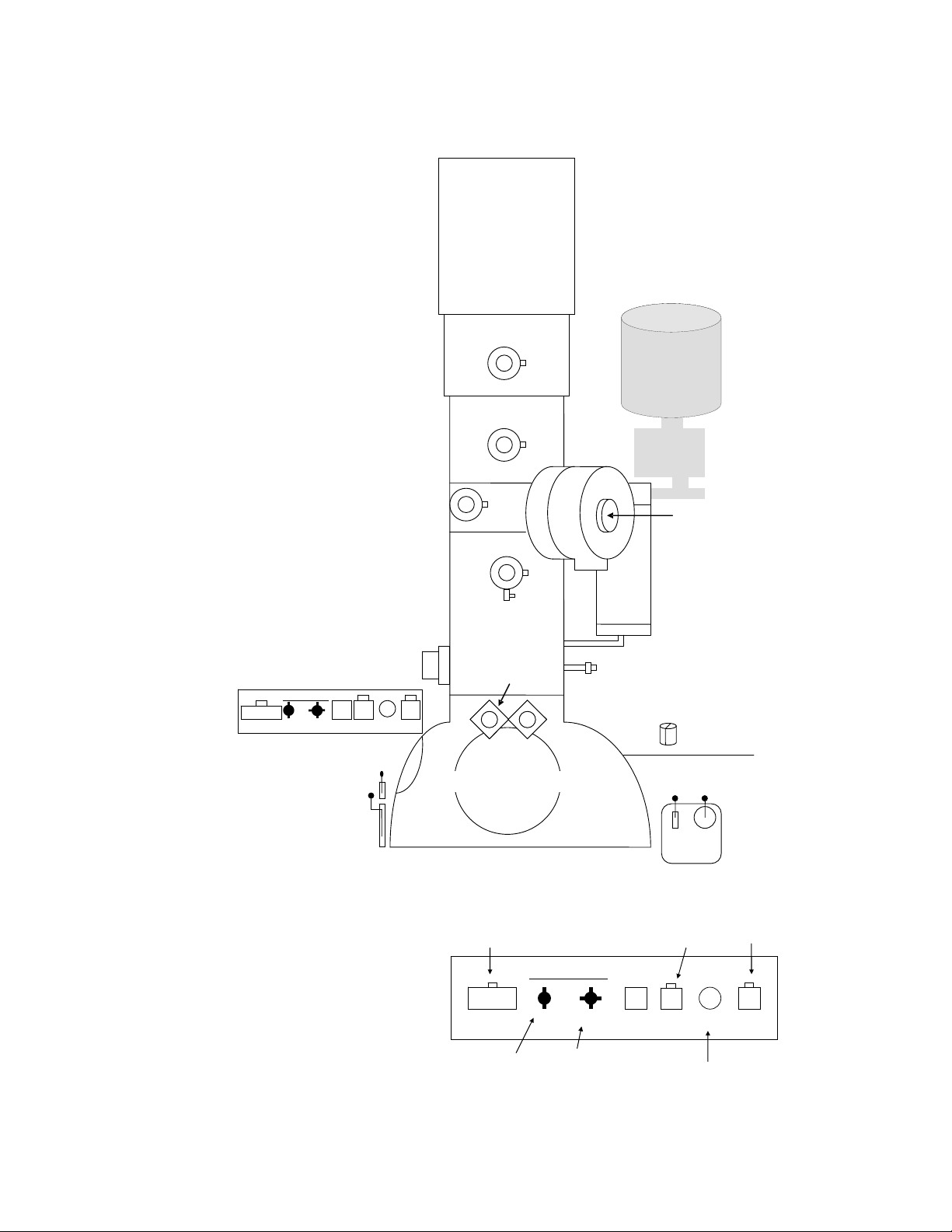
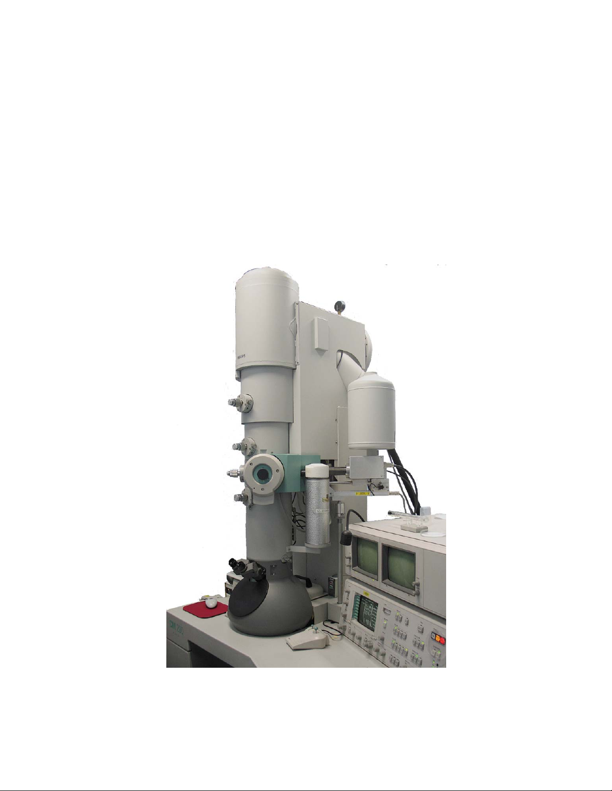
1. IMPORTANT PARTS OF THE PHILIPS CM200 TEM
r
r
r
r
r
r
j
r
Exposure
To the left of the column:
field emission gun (FEG)
condenser aperture 1
condenser aperture 2
Goniomete
RST WBL
Tilt Holder Intensity
side viewing window
focus stage leve
main stage leve
objective aperture
diffraction
aperture
fine
dewar
liquid N
2
for EDS system
specimen
holde
liquid N
container fo
cold finge
focus stage
viewe
gun valv e
control
Close Open
main viewing window
Film camera exposure
button
Goniometer
Goniometer
Exposure RST WBL
check camera
switch is set to CM
Tilt Holder Intensity
α-tilt control β-tilt control
(with floor pedal)
GUNVALVE
Z XY
oystick
intensity fine
adjustment
on/off
intensity
control
2
beam
beam
wobbler
4
cm200 user guide 2009
Page 5
The gun valve:
A
A
k
V
The Philips cm200 TEM uses a field emission gun (FEG) which provides very
high resolution but requires more care than a standard TEM filament. It is very
important that a high vacuum is maintained in the gun chamber at all times.
The gun chamber is sealed off from the rest of the column using the gun valve.
The gun valve must be closed whenever a specimen is being exchanged. If you
have a problem with the operation of the instrument or if you need to leave the
room, please close the gun valve by turning the control knob slowly clockwise
to the closed position.
The computer screen:
The cm200 contains many manual controls, such as focus and magnification.
However, many functions are controlled via a computer interface, using the
“softkeys” at the edges of the screen. To select a particular function press the
softkey next to the appropriate function title. To leave a page or function, press
the READY button at the lower right hand side of the screen. In most cases, this
will take you back to the HR-TEM BRIGHT FIELD page.
The functions described here are those required for most users. The other
functions must not be used unless you have received appropriate training.
DO NOT PRESS A SOFTKEY IF YOU DON’T KNOW WHAT IT DOES.
INT ZOOM
INT LIMIT
-
-
-
-
-
-
HR-TEM BRIGHT FIELD
LM
HT
spot 1
focusstep 1
defocus -4.30um
plate auto
meter XXX s
exp no
stoc
X: -141.61 um
Y: -78.72 um
Z: 135.69 um
: 0.00 d
B: 0.00 d
1000x
200k
350nm
E7773
50
MODES
PARAMETERS
UTOCON-1
COMPUSTAGE
RSET DEFOC
MEASURING
VACUUM
TEM CAMERA
HR-TEM BRIGHT FIELD page
¾ This page allows access to most of the functions of the microscope.
¾ The page is made up of three columns. The central column shows the
magnification, spotsize, focus step, film exposure information, film
stock levels, and stage positions.
¾ The right-hand column allows access to other pages in the program
via the softkeys. The most commonly required are COMPUSTAGE,
VACUUM STATUS and MODE SELECTION (MODES).
5
cm200 user guide 2009
Page 6
COMPUSTAGE page
A
A
k
V
¾ The
COMPUSTAGE allows stage position to be monitored and
controlled. Stage positions can be stored and recalled. The central
column on this page contains the same information as on the HRTEM BRIGHT FIELD page.
¾ To store a stage position, select a number in the right-hand column
on the monitor using a softkey (when selected, the number is
highlighted). Press the STORE softkey to save the position.
¾ To return to a saved position, select the appropriate number and
press the RECALL softkey on the right-hand side of the page. The
stage will automatically move to that position.
¾ To clear a saved stage position, select the appropriate number and
press the CLEAR softkey on the left-hand side of the page.
¾ To clear all saved stage positions, press the CLEAR ALL softkey twice
(located on the left-hand side of the page).
¾ The COMPUSTAGE page also contains functions for setting eucentric
height (A-WOBBLER) and for returning the specimen to zero tilt
(RESET AB). The RESET AB softkey must always be pressed before a
specimen is removed.
COMPUSTAGE REGISTER CONTROL
COMPUCTRL
Z DISPL = 0
Z DISPLAY
USER REAL
CLEAR
CLEAR ALL
XY RECALL-
RESET AB
-WOBBLER
LM
HT
spot 1
focusstep
plate auto
meter XXX s
exp no
stoc
X: -141.61 um
Y: -78.72 um
Z: 135.69 um
: 0.00 d
B: 0.00 d
1000x
200k
350nm
-defocus 44.30um
E7773
50
STORE
1
2
3
RECALL
6
cm200 user guide 2009
Page 7
VACUUM STATUS page
A
¾ The
VACUUM STATUS page shows a diagram of the vacuum system.
The status of the vacuum can be read at the top of the screen. Below
the diagram of the vacuum system is a series of pressure readings,
including the IGP (ion getter pump) reading.
P1: 32 P3: 34
P2: 49
¾ Before the gun valve is opened, the IGP reading must be less than 27
and the VACUUM STATUS must be ‘READY’.
MODE SELECTION page
¾ The modes page allows the user to select the TEM mode to be used.
Usually this is HR-TEM. The CONFIGURATION page can be
accessed from this page.
CONFIGURATION page
¾ This page contains information on the state of the microscope
(STANDBY or OPERATE) and on the extraction voltage. As the filament is
turned up, the change in extraction voltage (“Actual”) can be
monitored on this page.
IGP: 5
STANDBY
EXTR LIMIT
CONFIGURATION
FEG CONTROL
State: STANDBY
Time: 0 min
: 4.5 kV
ctual: 2.29 kV
--
DISPLAY
FIL OFF
7
cm200 user guide 2009
Page 8

2. CHECK cm200 STATUS
1. Log in to the EMU Booking System on the PC.
2. Check that the vacuum is OK by confirming that both the UHV and HV
indicators on the far right side of the panel are illuminated. If not, check
with EMU staff.
3. Go to the VACUUM STATUS page (from the HR-TEM page, press the
VACUUM softkey). Check that the vacuum status is READY and that the IGP
is less than 27. If not, check with EMU staff.
4. Return to the HR-TEM page (press READY).
5. Check that the High Tension indicator on the right side of the panel is lit. If
not, check with EMU staff.
6. Fill the liquid nitrogen dewar and place it under the cold finger. You must
wear safety glasses and protective gloves when handling liquid nitrogen.
7. Ensure that condenser aperture 4 and objective aperture 7 are selected and
that the diffraction aperture is out (swing shift to the right).
condenser aperture objective aperture diffraction aperture
1
1
7
7
2
2
3
3
4
4
32
32
1
1
6
6
5
5
4
4
cm200 user guide 2009
8
Page 9

3. TURN THE FILAMENT UP
1. Press the MODES softkey and then the CONFIGURATION softkey to go to
the CONFIGURATION page.
2. Turn the filament knob on the right-hand side of the
display screen slowly clockwise (three or four clicks at a
time).
Note: If the voltage is increased too quickly, the kV value
will freeze and you will need to seek assistance from
EMU staff.
Monitor the extraction voltage on the screen. When the
voltage approaches its limit (~4.5 kV), you will hear a
beep. Make sure you reach the maximum possible
voltage by turning the knob a few more clicks. The
voltage will usually reach 4.48 kV.
3. Press the READY button and then the HR-TEM softkey to return to the HRTEM BRIGHT FIELD page.
High tension
On
Off
Filament
3
cm200 user guide 2009
9
Page 10

4. LOAD THE SPECIMEN
There are two specimen holders available:
1) A single-tilt holder for conventional imaging and EDS analysis.
2) A low-background double tilt holder for crystallographic studies and
specialised EDS analysis (see appendix a).
When you begin your cm200 session the single-tilt holder will normally be in
the microscope.
Remove the single-tilt holder:
1. CHECK THAT THE GUN VALVE IS CLOSED. If not, close it by turning the
switch slowly clockwise.
2. Pull the specimen holder out until it cannot
be pulled any further (~8cm).
3. Rotate the holder clockwise as far as it will
go (~120º).
4. Pull the holder gently out of the airlock.
Take care not to knock the specimen holder against the airlock walls as it is
released.
5. Place the specimen holder in the support. Do not touch the brass part of the
specimen holder with your fingers.
6. Lift the specimen securing clamp using the special tool.
7. Load the specimen into the recessed ring, then gently lower the securing
clamp using the special tool.
8. Rotate the specimen holder slightly and gently tap it to ensure that the
specimen stays in place.
1
2
3
Insert the single-tilt holder:
1. CHECK THAT THE GUN VALVE IS CLOSED. If not close it by turning the
switch slowly clockwise.
2. Check the IGP reading by going to the VACUUM STATUS page. The IGP
reading should be less than 27. If not, check with EMU staff.
cm200 user guide 2009
10
Page 11

3. Insert the rod gently into the specimen airlock. Orient the rod so that the
large key peg is at the 11 o’clock position. Push the rod into the airlock until
you feel a stop and the red light on the airlock illuminates (this indicates that
the airlock is being pumped). After the pump has started it is often useful to
gently wiggle the rod, which allows it to be inserted another few
millimetres.
4. Wait until the red light has turned off.
5. Rotate the rod anti-clockwise (~120º) keeping a firm grip on the holder. The
vacuum will ‘grab’ the rod when it gets to the 6 o’clock position.
6. Guide the rod as it enters the airlock. The key peg should slide into the slot
on the airlock. Monitor any change in vacuum by noting the IGP value. (The
IGP value may rise above 27 during rod insertion – it must be 27 before
operation).
cm200 user guide 2009
11
Page 12

5. OBTAIN AN IMAGE
1. Check that the IGP reading is less than 27.
2. Go to the HR-TEM BRIGHT FIELD page (from the VACUUM page, press
READY).
3. Set the magnification to ~500x.
4. Open the gun valve by turning the switch slowly anti-clockwise. The beam
should appear on the viewing screen within a few seconds.
5. If the beam does not appear, check that the high tension indicator is still lit.
¾ If not, close the gun valve by turning the switch slowly clockwise and
check with EMU staff.
¾ If the high tension indicator is lit, check the magnification is ~500x and
that the objective aperture is set to 7.
¾ If you are examining an electro-polished specimen move the specimen
around using the X-Y joystick until you find the hole
6. Centre the beam using the X and Y shift
controls.
7. Spread the beam over the screen by
turning the INTENSITY knob.
8. Locate the area of interest on the
specimen and place it in the centre of
the stage using the X-Y joystick.
Intensity
The INTENSITY knob is
used to spread out &
concentrate the beam (left).
The SHIFT controls are
used to move the beam
around the stage to the
desired position (right).
ShiftYXShift
YX
cm200 user guide 2009
12
Page 13

6. SET THE EUCENTRIC HEIGHT
1. Increase the magnification to 5 -10K.
2. Spread the beam over the screen by turning the INTENSITY knob.
3. Move the beam to the centre of the screen using the X and Y SHIFT controls.
4. Move the specimen (X-Y joystick) so that a recognizable feature is in the
centre of the screen.
5. Go to the COMPUSTAGE page.
6. Press the A-WOBBLER softkey. This causes the specimen to tilt continuously
from +15º to -15º. If the specimen is not at eucentric height the image will
move back and forth on the screen.
7. Adjust the height of the specimen using the Z joystick until the movement of
the image is minimized.
8. Press the A-WOBBLER softkey to stop the specimen tilting.
7. FOCUS THE IMAGE
1. Check that the image is in focus using the FOCUS control. FOCUS STEP
(sensitivity of focus control) can be adjusted using the inner control knob.
¾ Use the small screen (lift by using the rear lever on the left-hand side
of the column) and the binocular microscope on the front of the
column to attain the best focus.
¾ Check that the binoculars are focused by inserting the pointer (right
hand side of the column; turn to insert) and adjust the eyepieces until
the image of the pointer is focused. To remove the pointer pull it out
and turn it to lock.
¾ When focusing, start with a large focus step (5 or 6) and get the best
focus you can before progressively reducing the focus step to achieve
fine focus (focus step 2 or 3).
cm200 user guide 2009
13
Page 14

8. MOVE AROUND THE SPECIMEN
¾ The X-Y joystick controls x-y movement of the specimen. The Z joystick
should be adjusted only when eucentric height is being set.
¾ The stage position can be monitored on the HR-TEM page or the
COMPUSTAGE page. On the COMPUSTAGE page, stage positions can be
stored and recalled (see section 1).
¾ Specimen tilt.
¾ a-tilt is available on both the single and double tilt holder. The
specimen is tilted by turning the TILT knob either clockwise or anticlockwise depending on the desired direction of the tilt. The extent to
which the knob is turned determines the tilt speed.
¾ B-tilt is available only with the double-tilt holder. The direction and
speed of the tilt are controlled by the HOLDER knob. The tilt is
controlled by the foot pedal
¾ Reset the specimen to 0º tilt by pressing RESET AB on the
COMPUSTAGE page.
cm200 user guide 2009
14
Page 15

9. CHECK THE MINOR ALIGNMENTS
The minor alignments should be checked at the start of each session, and may
be adjusted at any time. They should be performed whenever the condenser
aperture is changed.
Condenser aperture alignment
The aim of this alignment is to make the
beam expand and contract
concentrically.
1. Check that the objective aperture is out (position 7).
2. Focus the image.
3. Condense the beam to a fine spot using the intensity knob.
4. Centre the spot on the screen using the X and Y shift knobs.
5. Expand the spot using the INTENSITY knob until it is ~10cm in diameter.
6. Centre the spot on the screen using the condenser aperture drives.
34
5
7. Repeat from step 2 until the beam expands concentrically from the centre of
the screen.
Condenser stigmation alignment
The aim of this alignment is to make the
beam as circular as possible.
1. Check that the objective aperture is
out (position 7).
2. Set the magnification to ~50K.
3. Focus the image.
:
4. Press the STIG button on the right hand side of the console. The LED will
illuminate and the STIGMATOR CONTROL page will be displayed.
5. Select the COND softkey.
: ;
cm200 user guide 2009
15
Page 16

6. Condense the beam to a spot about 3cm in diameter using the INTENSITY
knob.
7. Adjust the beam so that it is as circular as possible using the X and Y
MULTIFUNCTION knobs on the right hand side of the console.
8. Press the STIG button to leave this function.
Pivot point alignment
If the pivot points are aligned, focussing at high magnifications is easier
1. Check that the objective aperture is out (position 7).
2. Set the magnification to ~50K.
3. Focus the image.
4. Condense the beam to a small spot.
5. Press the ALIGN button on the right hand side of the console. The LED will
illuminate and the ALIGNMENT SELECTION page will be displayed.
6. Press the PIVOT POINT X softkey. You should see two spots on the screen.
(If the spots are not visible you may need to reduce the magnification).
7. Use the MULTIFUNCTION X and Y knobs on the right hand side of the
console to make the two spots overlap. (Keep the spots in view by adjusting
the X and Y SHIFT controls, if necessary).
8. Press the PIVOT POINT Y softkey. You should see two spots on the screen.
(If the spots are not visible you may need to reduce the magnification).
9. Use the MULTIFUNCTION X and Y knobs on the right hand side of the
console to make the two spots overlap. (Keep the spots in view by adjusting
the X and Y SHIFT controls, if necessary).
10. Press the ALIGN button to leave this function.
cm200 user guide 2009
16
Page 17

10. INSERT AN OBJECTIVE APERTURE
There are 4 objective apertures available. The largest aperture (1) produces the
least image contrast; the smallest (4) produces the most contrast. Positions 5, 6
and 7 do not have an aperture.
1. Set magnification to 5-10K.
2. Condense the beam to a fine spot using the INTENSITY knob.
3. Press the D button on the right hand side of the console. This will produce a
diffraction pattern on the screen.
4. Turn the objective aperture control counter clockwise to select the desired
aperture.
5. Centre the aperture (the dim circle) over the bright spot using the aperture
alignment knobs. Be careful! The amount of movement required is very
small.
6. Press the D button again to go back to a normal (bright-field) image.
7. Spread the beam over the screen using the INTENSITY knob.
cm200 user guide 2009
17
Page 18

11. RECORD AN IMAGE ON PHOTOGRAPHIC FILM
1. CHECK THAT THE IMAGE SELECTOR SWITCH IS SET TO CM.
2. Align the area of interest on the centre of the screen.
The corners of the negative are marked by the middle
spot of each group of three spots. The data bar
(including the scale bar and exposure number)
occupies the far right of the image, so make sure that
your primary area of interest is not in this region.
3. Check that the image is in focus using the FOCUS
control. FOCUS STEP (sensitivity of focus control) can be adjusted using the
inner control knob.
¾ Use the small screen and the binocular microscope on the front of
the column to attain the best focus.
4. Spread the beam so that it covers the whole screen. The exposure time is set
automatically.
5. Note the exposure number. This number is the number of the next negative
to be used and will appear on the negative when it is developed.
6. Lift the main screen into the vertical position using the front lever on the
left-hand side of the column. The light on the EXPOSURE button on the lefthand side of the column will turn on.
¾ If the EXPOSURE light does not illuminate, check that there is still
film in the camera (stock) and that the exposure time is not too
long. The EXPOSURE light will not illuminate when the rotary
pump is operating – wait until it stops to take your image.
7. Press the exposure button. All of the console lights will turn off and the film
will be exposed.
8. Wait until the console lights turn back on and then lower the screen using
the lever on the left-hand side of the column. The EXPOSURE light will turn
off when the stage is lowered.
cm200 user guide 2009
18
Page 19

12. RECORD A DIGITAL IMAGE
1. CHECK THAT THE IMAGE SELECTOR SWITCH IS SET TO CCD.
2. Align the image in the centre of the screen. The digital camera captures the
area shown on the small screen (lift by using the rear lever on the left-hand
side of the column). The digital image will be rotated by 90º.
3. Check that the image is in focus using the FOCUS control. FOCUS STEP
(sensitivity of focus control) can be adjusted using the inner control knob.
¾ Use the small screen and the binocular microscope on the front of
the column to attain the best focus.
4. Spread the beam so that it covers the whole screen.
5. Start ANALYSIS on the PC by clicking on START>PROGRAMS>AnalySIS>
AnalySIS.
6. Lift the main screen into the vertical position using the front lever on the
left-hand side of the column.
7. Click on the ACQUIRE icon .
¾ This image is ‘live’ and will be refreshed every few seconds.
¾ The camera control icon controls the brightness/contrast.
Adjust the exposure time so that the intensity histogram is
normally centred (usually 1000ms).
8. Click on the
9. Click on the SCALEBAR icon to add a scale bar.
10. Save the image into your folder on the network (m:\images\cm200\your
user name).
11. Lower the stage to continue imaging.
SNAPSHOT icon to capture the image.
cm200 user guide 2009
19
Page 20

13. EXCHANGE SPECIMENS
1. Reduce the magnification to ~500x.
2. Remove the objective aperture by turning the aperture control fully
clockwise so that it is in position 7.
3. CLOSE THE GUN VALVE by turning the control knob slowly clockwise.
4. Ensure that the stage is at 0º tilt by going to the COMPUSTAGE page and
pressing the RESET AB softkey.
5. Pull the specimen holder out until it cannot be pulled any further (~8cm).
6. Rotate the specimen holder ~120º clockwise.
7. Pull the specimen holder gently out of the airlock.
8. Place the specimen holder in the support.
9. Lift the specimen securing clamp using the special tool.
10. Remove the specimen.
11. Insert the new specimen into the holder.
12. Lower the specimen securing clamp using the special tool.
13. Insert the specimen holder into the column as described in section 4.
cm200 user guide 2009
20
Page 21

14. END THE SESSION
1. Remove the specimen as described in section 13.
2. Insert the single tilt specimen holder into the column as described in section
4.
3. Go to the CONFIGURATION page by pressing MODES then
CONFIGURATION.
4. Press the STANDBY softkey to put the microscope into standby mode.
Check that the filament emission automatically reduces to ~2.29kV.
5. Clear any stored stage positions by going to the COMPUSTAGE page and
pressing CLEAR ALL twice.
6. Cover the TEM windows.
7. Exit from any programs that you have been running on the PC.
8. Log out of the EMU booking system.
cm200 user guide 2009
21
Page 22

Appendix a: Using the double tilt holder
The double-tilt holder may be used by advanced users for crystallographic
studies and/or specialised EDS analysis.
If you would like to use the double-tilt holder, contact a member of EMU staff
for training.
1. Close the gun valve and remove the single-tilt holder as described on pX.
2. Rest the double-tilt holder in the clear plastic support.
3. Unscrew and remove the beryllium ring using the tool provided (kept
in a plastic, snap-top tube).
4. Load your specimen into the circular recess in the holder.
5. Gently and carefully screw the beryllium ring into place to secure the
sample, using the tool provided.
AVOID CROSS-THREADING & DO NOT OVER-TIGHTEN THE RING
6. Rotate the specimen holder slightly and gently tap it to ensure that the
specimen remains in place.
7. Check the IGP reading by going to the
Open
VACUUM STATUS page. The reading
should be less than 27.
If not, check with EMU staff
8. Lower the shift on the airlock so that the
Close
circular slot is open.
9. Orient the rod so that the large key peg is at about 11 o’clock. Insert the rod
gently into the specimen airlock until the red light on the airlock illuminates
(this indicates that the airlock is being pumped). After the pump has started
it is often useful to gently wiggle the rod, which allows it to be inserted by
another centimetre or so.
DO NOT INSERT THE ROD FURTHER UNTIL THE RED LIGHT HAS TURNED
OFF.
10. The computer system will automatically sense that a double-tilt holder is
being inserted and will ask you to specify which specimen holder you are
using. On the computer interface, select
PHILIPS DOUBLE TILT and press READY.
Open
Close
cm200 user guide 2009
22
Page 23

11. As instructed on the screen, plug in the double-tilt holder cable to the right
side of the airlock and press READY.
12. Check that the red light is off.
13. Rotate the rod ~120° anti-clockwise 4, keeping a firm grip on the holder.
(The vacuum will ‘grab’ the rod when it gets to about 6 o’clock.)
14. Guide the rod as it enters the airlock. The key peg should slide into the slot on
the airlock. Monitor any change in vacuum by noting the IGP value. (IGP may
rise above 27 during rod insertion – it must be below 27 before operation).
cm200 user guide 2009
23
Page 24

Appendix b: Diffraction patterns
1. Select the required field of view with the sample at the appropriate tilt angle.
2. Insert a selected area diffraction aperture (if required) by turning the swing shift
to the left. Align the aperture over the area of interest.
3. Remove the objective aperture from the beam.
4. Press the D button.
5. Adjust magnification (camera length), focus and intensity to optimise the
pattern.
6. Centre the pattern on the screen with the MULTIFUNCTION X and Y knobs.
7. Record the pattern.
¾ Check that the image selector switch is set to CM.
¾ Select TEM CAMERA.
¾ Adjust MAN TIME to set the exposure time. For most patterns 1-2
seconds is appropriate. (Exposure time is best determined by running a
series of test exposures.)
¾ Note the exposure number.
¾ Lift the main screen.
¾ Press the exposure button.
¾ Wait until the console lights turn back on and then lower the main
screen.
8. Insert and align the objective aperture.
9. Remove the selected area diffraction aperture.
10. Press the D button to leave diffraction mode.
cm200 user guide 2009
24
Page 25

Appendix c: X-ray analysis
SEE EMU STAFF BEFORE ATTEMPTING X-RAY ANALYSIS FOR THE FIRST
TIME.
The Philips CM200 is equipped with an EDAX r-TEM system to perform energydispersive x-ray spectroscopy (EDS). We use a Sapphire Si(Li) EDAX detector
with 30mm2 active area. This is used to acquire and analyse chemical spectra
from the TEM sample. The software programs used to run the analyses operate
in a Windows™ environment and many of the functions of the software are
similar to other Windows-based programs.
These instructions are intended as a basic guide. For advanced software
features, please consult the mDX or iDX Reference Manual available from EMU
staff.
Getting Started
1. Start the EDS software by double-clicking on the mDX icon.
2. Locate the region of interest in the centre of the TEM viewing screen.
3. Remove the objective aperture.
4. Insert condenser aperture 3. Align the aperture (see p.23).
5. Tilt the specimen toward the detector by increasing the α-tilt to
approximately +15°.
6. Reduce the spot size to spot size 4. You may need to adjust the spot size
again later.
7. Position the beam over the area of interest using the
INTENSITY and BEAM SHIFT knobs.
8. Insert the EDS detector by pressing the red ANALYZE button
on the RTEM hardware control box.
RTEM
Analyze
Retracted
EDAX
9. Check the COUNT RATE (bottom left corner of the computer screen). It
should be between approximately 1000 counts per second (cps) and 4000
cps.
¾ If the count rate is much too high, the
detector will retract automatically. The
green RETRACTED button will flash.
Press the RETRACTED button to stop the flashing. Diagnose the cause
of the high count rate (e.g., objective aperture left in or Cu grid in
cm200 user guide 2009
25
Page 26

¾ If the count rate is over 4000cps but the detector does not
automatically retract, try decreasing the spot size to reach 10004000cps.
¾ If the count rate is too low (<~200cps), increase the spot size, re-
position the beam and re-acquire.
Acquiring a Spectrum
1. Click on the clock icon in the top left corner of the mDX menu bar to
start acquiring a spectrum. The icon will turn yellow when activated. The
spectrum will automatically acquire for 100 seconds. To stop acquisition at
any time, click on the clock icon again (it will turn grey).
2. Check the count rate and adjust if necessary.
Modify Spectrum Appearance
1. The scale of the spectrum can be manipulated by holding down the left
mouse button and moving the mouse left, right, up or down. The spectrum
can be expanded or contracted by pressing the appropriate buttons on the
toolbar:
¾ Expand/contract horizontally:
¾ Expand/contract vertically:
¾ Press the house icon
2. Add text to the spectrum by selecting ADD TEXT from the EDIT menu.
Click on the spectrum at the point where the text is to be added and enter
the text in the box that appears. Press ENTER to place the text on the
spectrum. The text can be edited or removed at any time by re-selecting
ADD TEXT from the EDIT menu and then clicking on the text.
3. Add text to the spectrum header by selecting LABEL from the EDIT menu,
enter a label in the box and press OK.
4. Erase a spectrum by pressing the paint-roller icon in the top left corner
of the screen.
cm200 user guide 2009
to restore the full spectrum.
26
Page 27

Savin Spectral Data
s
m
ppr
a
p
e
y
w
o
g
e
g
h
e
m
u
e
e
o
m
-
x
g
d
a
i
p
l
T
t
o
e
n
e
t
u
u
e
n
a
g
c
e
r
K
I
i
C
g
g
o
x
o
a
p
gh
e
A
h
d
a
s
y
o
s
e
t
y
s
M
d
m
a
d
c
a
e
e
f
a
L
i
e
s
m
L
p
m
S
i
s
h
e
M
E
f
O
t
s
e
o
2
0
. Save file
1
. Spectru
2
to your username folder under M:\ > IMAGES > CM200.
files can be saved in .spc, .tif, .csv or .bmp format.
¾ .s
¾ .tiinf and .bmp
¾ .c
Qua
itative Elemental Analysis
he EDS sys
q
ualitative
u
sers should
a
nalysis.
. The seri
1
screen a
the PEA
IDENTIF
screen.
c files can
actice to s
fu
ture.
most ima
sv files sav
e allows th
fil
s
ch as Micr
em we us
r semi-qua
consider u
s of icons i
e used for
IDENTIFI
CATION d
only be o
ve these fil
files save t
ing softwar
a spectru
user to re
soft Excel.
is almost
titative da
sing the mi
n the top ri
nterpretin
ATION ic
ialogue bo
ened by th
es in case
e spectru
programs
trace as
raph the
xclusively
a. For acc
croprobe o
ht corner
the spectr
n to o
on the ri
mDX soft
ou need t
as a pictu. re that can be opened
and y dat
ata in a sp
sed for th
rate quanti
r performin
f the mDX
l data. Sel
en the PE
t side of t
are. It is
manipulat
points. Th
readsheet
acquisitio
tative data
mass spe
ct
K
e
ood
them in
s type of
rogram
of
nalysis,
trometric
2
. Click on
3
. Check th
. Manuall
4
cm2
identify
element
definitel
clicking
box. Thi
associat
incorrec
ELEM bo
element
POS ELE
0 user gui
the AUTO
nd label th
will also a
at each aut
associate
n the ele
will displ
d with that
ly identifie
x and click
identify a
associated
box. Cli
e 2009
button. Thi
e main pe
ppear in th
omatically
with a par
ent (e.g., F
y all of the
element. I
, select th
on the DE
peak by cl
with that
k on a pos
s will auto
ks. The list
SAVED E
identified
ticular ele
K) in the
peak posit
a peak ha
t element i
ETE box to
cking on t
nergy valu
ible eleme
atically
of identifie
EM box.
eak is
ent by
AVED ELE
ons
been
n the SAV
remove it
e peak itse
(keV) will
nt in the P
d
D
rom the lis
lf. The pos
be display
S ELEM b
.
ible
d in the
x to display
7
Page 28

all of the peak locations associated with that element. When you identify an
element, click on ADD to add the element to the SAVED ELEM box.
Adjust the Display Characteristics
1. Element labels can be removed individually from
the spectrum (and SAVED ELEM box) by
highlighting them and clicking on the DELETE
button. Clicking on the DELETE ALL button will
remove all peak labels and will clear the SAVED
ELEM box.Select the ALPHA LINES ONLY box to
remove labels from all peaks except the α peaks.
2. Select ELEM to label peaks by element (e.g., Cu or Sn); SHELL to label peaks
by their electron shell level (e.g., CuK or SnL); or TRANS to label peaks by
their transition type (e.g., CuKa or SnLb).
3. Select EPIC to bring up a periodic table with x-ray energies to assist in peak
identification. Select an element and click on ENERGY TABLE to display
peak energies.
Regions of Interest (ROI)
Energy ranges (regions of interest) representing certain element peaks can be
selected for use in elemental mapping (see p.44). Peaks falling within the
selected ROI will be shaded (default colour is grey).
To remove an ROI label, select the the ROI icon and click on the DELETE
button. Select DELETE ALL to remove all ROI labels at once.
Comparing Two Spectra
1. Click on VIEW on the menu bar and select
COMPARE. A COMPARE SPECTRA window will
appear showing the name of the last spectrum
acquired as Spectrum A.
2. Click on the OVERLAY box.
3. Open a second, saved spectrum by clicking on
OPEN. Select your second spectrum for
comparison (Spectrum B).
4. Click on OK. The two spectra will be overlayed
for comparison.
cm200 user guide 2009
28
Page 29

Opening a Saved Spectrum
1. To open a previously saved spectrum, click on FILE > OPEN, locate your
folder and file and click on OK.
2. A FILE or CURRENT PARAMETERS dialogue box
will appear with a selection of display options. For
most applications, ensure that all the FILE options
are selected. This will display the spectrum in the
same format as it was saved.
3. Select the VIEW option to look at the parameters
stored with the saved spectrum.
4. Click OK to open the spectrum.
Semi-Quantitative Analysis
The mDX program’s QUANTIFY function allows the user to perform semiquantitative elemental analysis of a sample. Proper quantitative analyses can be
conducted but require replicate analyses and the careful preparation and use of
standards in order to assess the accuracy and precision of the results.
Using mDX, first identify the elements to be quantified, subtract the
background, and select the appropriate set of correction parameters. The
following description is generic and should be modified depending on the
nature of the quantification to be performed. Consult the reference manual and
EMU staff for assistance.
1. Click on the QUANT icon in the top right corner of the computer
screen. The QUANTIFY control panel will appear.
2. Click on the button. A Z LIST dialogue box will appear,
listing the elements to be quantified.
3. Select or de-select the elements to be quantified by clicking on them. Click
OK.
4. Click on the button. A BACKGROUND display panel
will appear.
5. Select SET to generate a list of elements identified using the qualitative
analysis in the AUTO field. These elements are used to determine the
background radiation.
cm200 user guide 2009
29
Page 30

6
f
d
C
u
u
x
X
I
t
n
m
a
o
e
)
l
u
r
r
d
m
e
o
n
y
u
c
o
r
d
k
r
.
N
e
L
g
e
m
r
l
c
o
o
h
a
t
o
A
s
c
o
r
e
s
u
e
e
t
T
a
e
t
R
O
d
t
N
H
d
O
a
A
c
s
R
s
x
r
f
p
n
n
d
a
D
c
w
a
3
0
. Click on
SUBTRA
backgro
backgro
the – (subt
T field to
nd. Select
nd to the s
act) button
remove the
UNDO to
pectrum.
in the
estore the
. Click on
7
. Click on
8
open the
which e
intensity
oxide mi
select O
9
. Click on
quantific
QUANT
I
you need
1
0. Click on
applied.
For most
dependi
approxi
denotes
absorpti
the QUAN
the
TYPE cont
cludes oxi
has been
xtures (wh
IDES.
the
ation calcu
FICATION
o define y
the
A correctio
applicatio
on the t
ation calc
bsorption
n correcti
T icon
ol panel.
es from th
easured, E
re the oxy
lation to b
panel. In
ur own co
n factor wi
s, select ei
pe of corre
lations, IN
orrection
n calculati
button to
ormally, t
quantific
EMENTS s
en peak in
butt
used. A K
ost cases,
rection fa
butt
l appear in
ther INTEN
ction requi
TEN denot
alculation
ns with fl
e ELEMEN
tion calcul
hould be s
ensity has
n to select
B FACTO
elect THE
tors/metho
n to select
the QUA
only or T
ed. THIN
s intensity
and FLU
orescence.
S option i
tions. If o
lected. Fo
not been m
he type of
S field ap
.
, see Paul Munroe.
he correcti
TIFICATIO
IN, INTEN
enotes thi
calculatio
RESENCE
selected,
ygen peak
analysis o
easured),
ears in the
on factors
N panel.
and ABS,
s, ABS
enotes
1
1. Click on
1
2. The resu
cm2
you hav
window
~200nm
Save res
0 user gui
the
elected to
will appea
, a-tilt valu
ts will be
lts by clic
e 2009
button to
do an abs
. Enter the
e and the n
isplayed in
ing on the
perform th
rption corr
nominal sp
ominal spe
a QUANT
bu
quantific
ction, an
ecimen thi
cimen den
IFICATION
ton in the
tion calcul
BS CON
kness (typi
ity and cli
RESULTS
ESULTS p
tions. If
ITIONS
cally
k OK.
indow.
nel.
0
Page 31

Ending the EDS Session
1. Remove the EDS detector by pressing the green RETRACTED button on the
RTEM hardware control box to the right of the column.
2. Press the AB RESET softkey on the COMPUSTAGE page to return the
specimen to 0° tilt.
3. Insert and align condenser aperture 4 (see p.15).
4. Exit the mDX program.
5. End the session as described in section 14.
cm200 user guide 2009
31
Page 32

Appendix d: X-ray mapping/line scans
X-ray maps can be made using the iDX software installed on the computer
attached to the CM200. A map is a two-dimensional representation of
elemental distribution in a sample. A map is made by obtaining an STEM
image, transferring the STEM image to the PC, and acquiring spectra across the
selected sample area on a pixel-by-pixel basis.
SEE EMU STAFF BEFORE ATTEMPTING THIS FOR THE FIRST TIME.
Getting Started
1. Check that the image selector switch is set to CM.
2. Obtain a well-focused image on the TEM viewing screen.
3. Tilt the specimen so that an α-tilt of approximately +15° is achieved.
4. Insert and align condenser aperture 3 (see p.15).
5. Align the condenser stigmator (see p.15).
6. Remove the objective aperture.
7. Adjust the magnification to 10,000-20,000x.
8. Condense the beam to a small spot, centre the beam using the X and Y shift
controls, and press the D button to obtain a diffraction pattern.
Obtaining a STEM Image
1. Press the MODES softkey and then press the SCAN BF-DF softkey twice to
view the SCANNING page.
2. Lift the TEM stage and a STEM image should be displayed on the two
monitors on the top of the microscope console. The bright-field image
should be visible on the left monitor, and a dark-field image on the right.
(The magnification may need to be reduced to ~20,000x using the
magnification control.)
3. Ensure that the bright-field image is active. Two LEDs below the screen will
be illuminated when the screen is active. Use the DETECTOR
CONTROL button in the SIGNAL CONTROL area of the STEM
controls to toggle between the screens.
4. Centre the beam.
'
I. Press ALIGN go to the ALIGNMENT SELECTION page.
cm200 user guide 2009
32
Page 33

II. Press the DET ALIGNM softkey
III. Centre the illumination on the bright field image using the X and Y
MULTIFUNCTION controls. The magnification may need to be
reduced in order to see the illumination spot. If magnification is
changed, the DET ALIGNM softkey must be pressed again in order to
activate the X and Y MULTIFUNCTION knobs.
IV. Press ALIGN to exit the ALIGNMENT SELECTION page.
5. Optimise the image.
¾ Adjust the image position, magnification and focus using the
standard TEM controls. The STEM image may be rotated by turning
the MULTIFUNCTION X knob.
¾ Adjust the brightness and contrast of the image using the
BRIGHTNESS and CONTRAST controls on the STEM control panel.
¾ Adjust the SCAN RATE at any time by selecting the appropriate
button: SLOW or FAST.
Collecting the Electron Image
1. Enable external control of the microscope by pressing the EXP 3 button on
the PHOTO SCAN RATE section of the STEM control panel.
2. Open the iDX program.
3. Click on the icon in the toolbar to acquire an electron
image (or select COLLECT > ELECTRON IMAGE). The image will be
refreshed continuously until the icon is pressed again.
4. Adjust image parameters.
I. Click on the icon.
II. Select the matrix size.
III. Enter the magnification.
IV. Display a micron bar by selecting MICRON BAR from the DISPLAY
menu.
V. Adjust the brightness and contrast of the image using the
BRIGHTNESS and CONTRAST controls on the STEM control panel.
cm200 user guide 2009
33
Page 34

Select regions of interest
e
e
c
o
P
p
n
o
O
n
a
i
k
s
8
d
e
e
e
(
a
A
y
O
a
a
n
l
r
n
l
e
y
E
p
A
a
n
s
o
t
O
e
a
t
O
M
s
d
i
w
s
D
t
n
n
t
t
m
p
o
w
e
D
h
e
w
t
O
.
e
D
t
n
h
l
x
k
t
y
e
A
e
a
E
e
L
V
g
3
0
. Insert th
1
hardwar
EDS dete
control b
tor by pres
x.
sing the red ANALYZE button on the RTEM
. Select S
2
acquire.
on the s
again.
3
. Select th
. Click on
4
and labe
also app
5
. Check th
associat
element
display
If a peak
in the S
remove i
6
. Manuall
possible
in the P
display
identify
box.
ECTRUM f
Acquisitio
ectrum to
PEAK ID
the AUTO
l the main
ar in the S
at each aut
d with a p
e.g., FeK) i
ll the peak
has been i
VED ELEM
t from the l
identify a
elements a
S ELEM b
ll the peak
n element,
rom the C
can be sta
lbar. Stop t
NTIFICATI
button. Thi
eaks. The
VED ELE
omatically
rticular ele
n the SAVE
positions a
correctly i
box and cl
ist.
peak by cl
sociated
x. Click on
locations a
click on A
LLECT me
rted manu
he acquisit
N icon
s will auto
list of ident
box.
identified
ment by cli
D ELEM b
sociated
entified, s
ick on the
cking on t
ith that en
a possible
sociated
D to add
u. A spect
lly by clic
on by pres
.
atically id
ified eleme
eak is defi
cking on t
x. This will
ith that ele
lect that e
ELETE bo
e peak itse
rgy value (
element in
ith that ele
he elemen
rum should
ing on the
ing the
entify
nts will
itely
e
ment.
ement
to
lf. The
eV) will b
the POS E
ment. Whe
t to the SA
in to
be
button
button
displayed
EM box to
n you
ED ELEM
. Click on
7
(ROI) pa
previous
.
Click on
range fo
panel. A
the ROI
of the el
the list b
0 user gui
cm2
the bu
el on the r
y saved R
the AUTO
all of the
individua
ist will be
ments liste
selecting
e 2009
ton to ope
ight side of
I by clicki
button. Thi
lements in
l map of ea
cquired. If
d, remove
he elemen
the REGI
the screen
on DELE
s will creat
the PEAK I
ch of the el
you do no
he unwant
and clicki
NS OF IN
Delete an
TE ALL.
a ROI en
ENTIFIC
ements sel
want to m
ed element
ng on DEL
TEREST
rgy
TION
cted in
p all
(s) from
TE.
4
Page 35

Acquiring a map
1. Click on the button to open the X-MAPS PARAMETERS panel.
2. Adjust the resolution of the image/maps by changing the size of the MATRIX
(# data points/pixels) and the DWELL TIME.
¾ Usually a 128 x 100 collection matrix with a 10ms dwell time is
sufficient to obtain at least a preliminary idea of the results.
¾ A 256 x 200 collection matrix with a 10ms dwell time usually takes
~20 minutes, depending on the number of elements to be mapped.
¾ Increasing the dwell time and the matrix size will increase the
resolution, but will also increase the acquisition time.
3. Click on the button to start the acquisition (or select X-RAY MAPS from
the COLLECT menu).
¾ A prompt will ask for a filename. Filenames must be ≤4 characters
long. Enter an appropriate filename and select your folder (under M:
> Images > CM200). Files will be saved as bitmaps; file size depends
on the size of the collection matrix. Click OK.
¾ A prompt box will display the collection parameters you have
chosen. Click on YES to start the map acquisition.
¾ To stop the acquisition at any time, click on the button again (or
select STOP from the COLLECT menu).
¾ The maps are automatically saved when acquisition is complete.
Acquiring a line scan
1. Click on the icon to open the LINE SCAN PARAMETERS panel.
2. Click the icon to activate the line drawing function.
3. Click and drag on the image to draw a line. To redraw the line, click on the
icon again.
4. Adjust the parameters of the line scan.
¾ Select the number of points.
cm200 user guide 2009
35
Page 36

¾ Select the dwell time.
¾ The estimated time for the line scan is displayed in the status bar.
5. Click on the icon to start the acquisition.
¾ A prompt will ask for a file name. Select your folder (under
M:>images>cm200). Files will be saved as .csv files. They may be
imported into MS Excel spreadsheets.
Acquiring further maps/line scans
1. Press the SLOW (or FAST) button on the VIEWING SCAN RATE panel to
return to STEM mode.
2. Adjust the image as required (position, brightness, contrast, magnification,
etc.).
3. Continue as described from Collecting the Electron Image (p.33).
Ending the Mapping Session
1. Remove the detector by pressing the green RETRACTED button on the RTEM
hardware control box to the right of the column.
2. Press the SLOW button on the VIEWING SCAN RATE panel to return to
STEM mode.
3. Lower the viewing screen on the TEM.
4. Press the MODES softkey and press HR-TEM twice to return to the HR-TEM
main page.
5. Go to the COMPUSTAGE page and press the RESET AB softkey to return the
specimen to 0° tilt.
6. Insert and align condenser aperture 4 (see p. 15).
7. Quit the iDX software.
8. Log out of the EMU system and turn off the monitor.
cm200 user guide 2009
36
 Loading...