

Page 1
FEI/PHILIPS CM120 TEM
Overview.
CM120 is a transmission electron microscope with a maximum acceleration voltage of 120 kV.
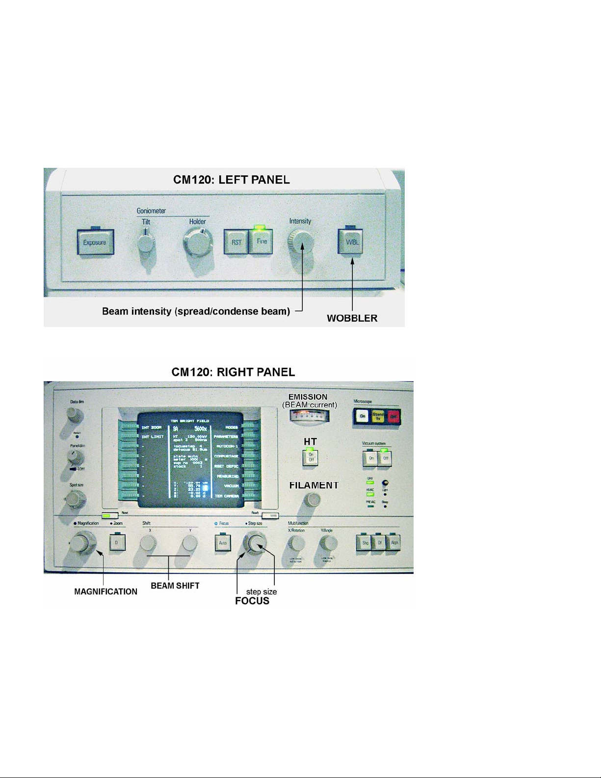
The main microscope controls are localized on the LEFT and RIGHT panels:
The left panel – contains
only two controls
important for users to
know:
• Intensity (beam).
• WOBBLER (for focusing).
The right panel –
contains most of the
CM120 controls:
• Microscope ON/OFF switch.
• Vacuum system ON/OFF switch
(in normal operation the OFF
switch is lit).
• Ultra High Vacuum (UHV)
indicator (normally is lit).
• High Vacuum (HIVAC) indicator
(normally is lit).
• High Tension (HT) button
(normally is lit).
• Filament knob.
• Emission (beam current)
indicator.
• Computer monitor.
• Spot size knob.
• Magnification knob.
• Focus knob.
• Beam shift, X and Y.
Page 2
Computer monitor.
An internal computer controls all
microscope functions. The
computer monitor on the right
panel provides all information
about the microscope’s condition.
Information on the computer is
organized into “pages.”
Computer has no keyboard, but is
operated by the green buttons on
the left and right sides of the
screen. These buttons function in
two ways: (1) select/change the
page and (2) set/change the
parameters. The buttons function
differently on different pages
depending on the content. There
is a magical button called
“Ready” on the bottom-right side
of the monitor. It takes you one
step back in the Menu hierarchy. Sometime it also functions as an “Enter” button. Combine the
green and “Ready” buttons to change the screen pages. The hierarchy of the pages is: CM120
MODES TEM LOW DOSE…
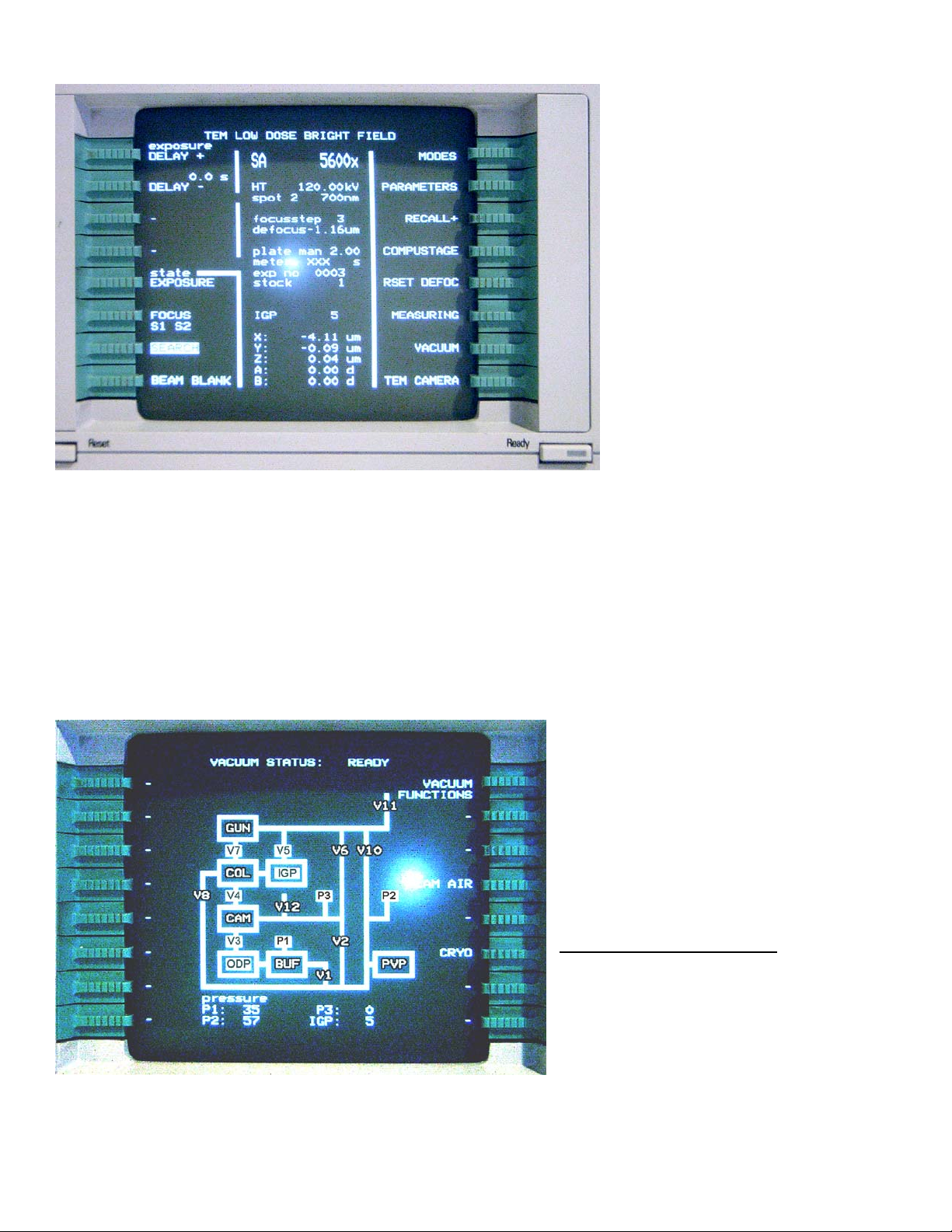
The “TEM Low Dose Bright Field” screen (seen above) is normally used for everyday operation. It
contains three fields: left and right fields label the green buttons (MODES, COMPUSTAGE and
VACUUM are commonly used); the central field contains information about the microscope status.
Most information is self-explanatory: magnification, accelerating voltage, spot size etc. Many options
for the green buttons are also self-explanatory. For instance, pressing the green button next to the
“VACUUM” will bring up the CM120 vacuum diagram:
On the diagram, a white background
indicates that a valve is open (V7), black
– closed (V10). For proper microscope
operation the following conditions must
be met:
V3, V4, V5, and V7 valves – open;
P3 and IGP reading (bottom of the
page) – less than 30.
Abbreviation used on this page:
Getter Pump; ODP – Oil Diffusion Pump; PVP –
Mechanical Pump; BUF – buffer tank; CAM –
photo camera; COL – column; GUN – electron
gun.
Similarly, other functions may be
accessed by pressing the corresponding
green button. Pressing “Ready” returns you to the previous screen.
IGP – Ion
Page 3
Grid-holder.
For those who have had previous experience with JEOL microscopes, CM120 holder will feel very
fragile and delicate. It’s very true. Please, pay special attention when handling FEI/Phillips holders –
they ARE really fragile and delicate! Before using, inspect the holder: check the O-ring for cracks or
dust, it must be clean; Check conical area next to the O-ring – it must be clean without visual
scratches etc; Inspect clamp mechanism, make sure it’s not damaged. Report any problem
immediately! Please, be aware: most of the FEI/Phillips holders could hold only one grid!
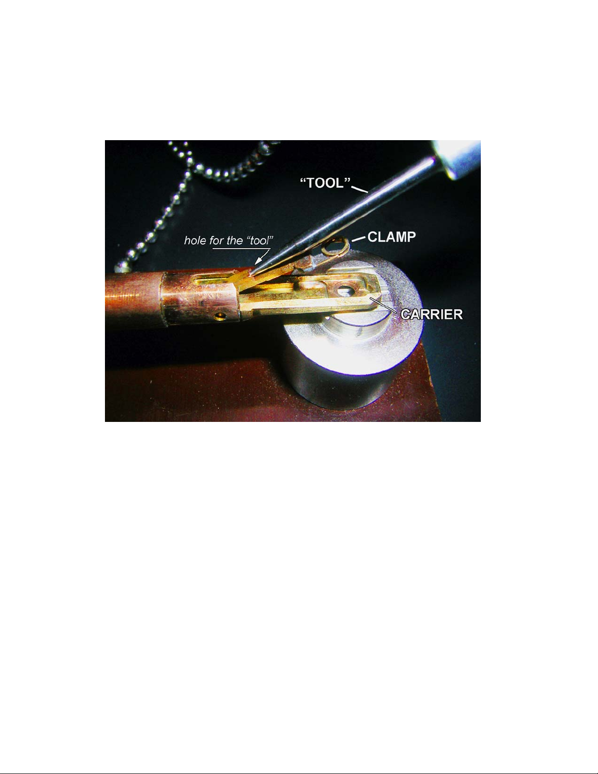
How to load the grid?
There is a special “tool” to open the “clamp,” which holds the grid in the “carrier.” In order to open the clamp,
(1) locate the small hole at the base of the clamp. (2) Insert the tool into the hole and slowly move the clamp up
into a vertical position (make sure the clamp is secured in this position); do not apply excessive force! (3)
When clamp is in the vertical position, load the grid into the carrier; make sure it’s centered well and slowly
move clamp down into the closed position. Control this movement with the tool. Do not remove the tool from
the hole unless clamp is completely closed. The normal orientation for the grid is sample down. Do not use
tweezers etc. to manipulate the clamp. Improper operation will damage the clamp mechanism.
Page 4

Using the CM120 Electron Microscope, basic operation.
Remarks: in this Instruction, references to the computer screen page/function associated with green
buttons are presented in BOLD GREEN. The name of the physical switch/knob/button – BOLD RED.
Parameters, which operators need to set/change (like magnification) – BOLD BLUE.
Step-by-step Instruction.
1. Make sure that HT, UHV and HIVAC indicators on the right panel are lit.
2. Go to TEM Low Dose Bright Field page using green/READY buttons: MODES TEM LOW
DOSE TEM Low Dose Bright Field.
This is your Main page.
3. Check the vacuum in the scope: VACUUM. Make sure that V3, V4, V5 and V7 are
opened; IGP < 30 and P3 < 30. Using Ready, return to TEM Low Dose Bright Field page.
Note: you also may see IGP readings on the TEM Low Dose Bright Field page.
4. If liquid nitrogen is used in anticontamination device, check the level. Add more if necessary.
5. Reset the holder: TEM Low Dose Bright Field COMPUSTAGE COMPUCTRL
RESET HOLDER.
6. Return to TEM Low Dose Bright Field page. Make sure that X, Y, Z, A, B is close to zero.
7. Make sure FILAMENT is OFF: rotate knob a few turns counterclockwise.
Page 5
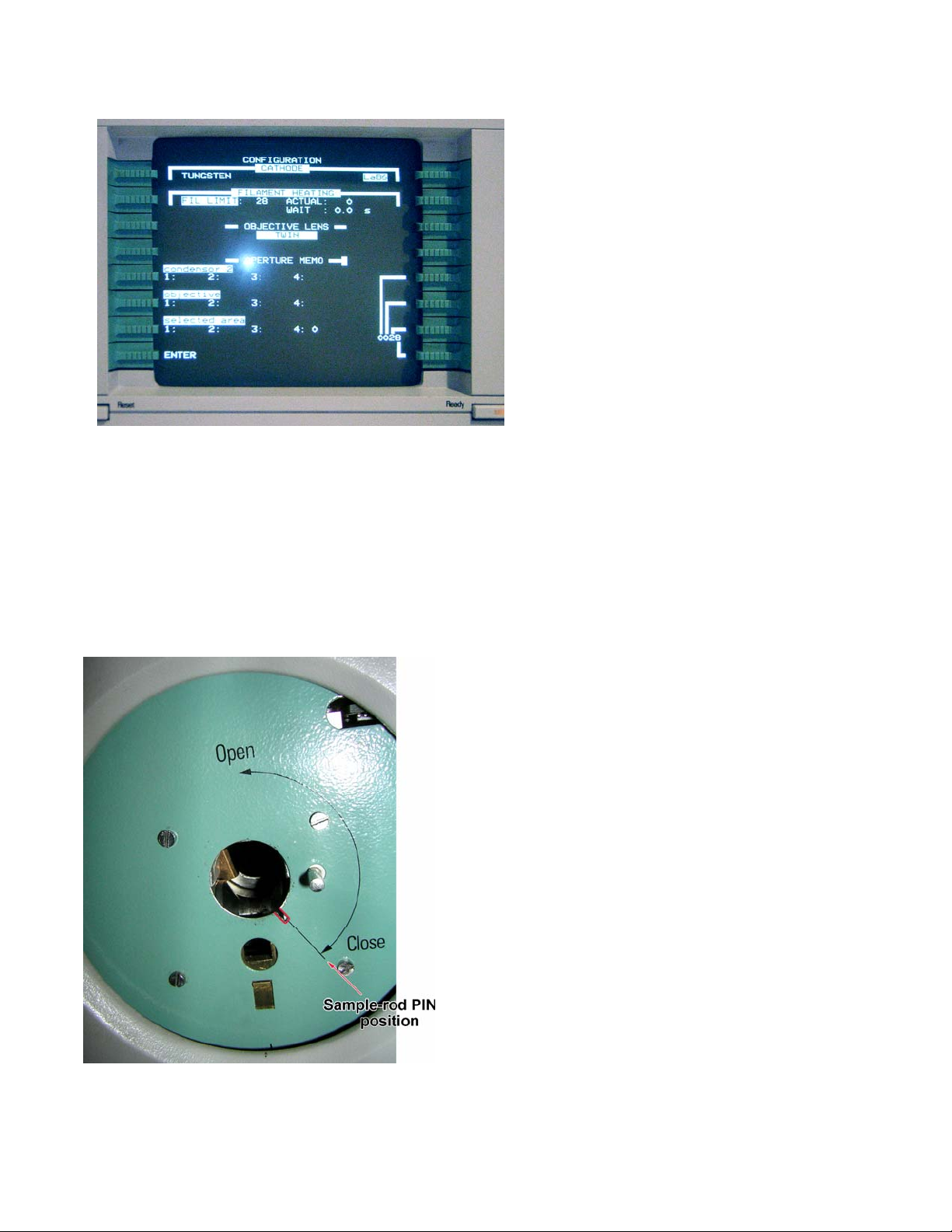
8. Check microscope’s configuration:
MODES CONFIGURATION.
Make sure that Cathode is set to
LaB6; Filament Limit is highlighted
and between 25 and 30 (28
currently).
9. Return to TEM Low Dose Bright
Field page.
10. Please, notice that CM120 has High
Tension (high voltage) ON all the time
(HT is lit).
11. Set magnification SA x5600 using
MAGNIFICATION (right panel).
12. Turn FILAMENT ON: make a few clockwise turns of the FILAMENT knob to initiate 2-3 min.
long program of LaB6 filament heating. Progress may be observed in the MODES
CONFIGURATION page, in Filament Limit, Actual. Observe, also, EMISSION (beam current)
increase. It will beep once when filament is ready.
13. Observe the beam on the big fluorescent microscope screen.
14. Using SHIFT X and Y (beam shift) on the right panel of the microscope, center the beam.
Spread and condense beam (INTENSITY, left panel) a few times to make sure it’s centered
well and symmetrical.
15. Turn OFF FILAMENT.
16. Insert the sample holder:
1. Load the specimen (grid) in the standard single tilt holder.
Make sure the specimen is properly fastened in the specimen
holder.
2. Check that the O-ring and conical surface of the holder is
clean.
3. Make sure that the filament is OFF.
4. Locate a small pin on the end of the holder closer to the grid.
5. Carefully insert the holder into the goniometer compustage
with the small pin on the holder in the 5 o’clock position. The
prepumping cycle will initiate and the red indicator light will come
on.
6. If necessary, select holder from Menu. Normally, “St Cryo
Holder” is used (choose one and hit Ready).
7. When the red light goes off (about 1 minute), rotate the
specimen holder fully counterclockwise until it does not rotate
further and insert into the microscope carefully as it will be
sucked into the vacuum of the microscope.
8. Reverse these directions to remove the specimen holder
from the microscope.
The filament should be OFF during all these procedures!
17. Wait for IGP < 30 (VACUUM or TEM Low Dose Bright Field page) before proceeding. Do not
use the microscope if the IGP reading is higher than 30 to prevent damage to the LaB6
filament!
Page 6

18. Turn ON FILAMENT (see #12).
19. Set Spotsize (right panel) to 3-4, find a small recognizable object on fluorescent screen using
joystick XY control; adjust illumination (INTENSITY,
left panel).
20. Press A-WOBBLER in COMPUSTAGE page (this
will initiate back and forth tilting of the goniometer to
+/- 15o). Using Z control on the joystick, align Z-High
by minimizing the apparent movement of the
centered feature.
21. Stop A-WOBBLER and press the Auto Focus knob
(right panel, next to FOCUS knob). Make sure that
stage is not tilted: A and B=0. If not – Reset AB on
the COMPUSTAGE page.
22. Focus desired object using the FOCUS. Note:
FOCUS knob has a “step size” sub-button (smaller
one) – step size determines how quickly focus is
changing. Normally, step size should not exceed “5”.
Step size is indicated on Main page along with
magnification, HT etc.
23. Use joystick XY to move the grid. Observe your sample using standard EM procedure.
24. Use digital camera to take the pictures. EMMENU4 software is used on CM120 microscope. In
order to use digital camera, you need to manually lift up a big microscope fluorescent screen.
25. Ending your session:
• Set MAG to 5600x.
• Spread the beam over the viewing screen.
• Turn OFF the filament.
• Reset the Holder (see #5 above).
• Take out the holder, remove your grid.
• Put holder in the desired storage place.
• If you are the last person, who is using microscope for the day and liquid
nitrogen was used, please, remove Dewar flask from the microscope, empty it
and place it on the microscope console in an upside down position, initiate
cryo-cycle on the microscope (VACUUM CRYO START).
26. Transfer your files to flash-drive, DVD, FTP etc. Do not store your images on microscope’s
computer – please, clean your directory often. EICN have no responsibility for your files on
any of EICN computers – they may be erased without notification.
27. Sign-in the log-sheet, report any problems, abnormalities with the scope.
28. Check CLMS to make sure that your actual timing on the scope is correct. Please, be advised
that EICN personnel are not responsible for proper timing of your microscope’s usage.
You are done! Many thanks for your patience and respect for our instruments!
Page 7

EMMENU4 overview.
EMMENU4 software operates the TIETZ F224HD CCD camera on CM120 TEM. The main element of
EMMENU4 is a “viewport”. It contains the whole interface for the digital camera: controls (photo,
video etc), settings (exposure time, image size, binning etc), measuring tools, FFT and a “screen”
to see the picture. You may create multiple viewports with different settings. On top of that, every
viewport also comes with two sets of settings: Camera 1 and Camera 2. So you may switch
between them as well! Because there is only one physical camera, only one viewport may be
active (you choose which one). Active viewport is connected to the “buffer” or “slot”. It is just an
allocation of virtual memory for the future picture. There are 500 buffers currently available. Every
time you take a picture – the camera writes the data to the buffer. Attention: by default, the
camera writes in the same “buffer” and erases the previous picture! Make sure that you choose
the next available slot for the next picture. To avoid this problem, you need to mark “save acquired
images on HD” in Tools Options Image Manager. Please, specify Directory and
establish filename “rules.” EMMENU4 image format is TIFF. Besides this virtual camera thing,
EMMENU4 has a set of standard features including histogram, image controls, measuring tool etc.
We strongly encourage users to study the EMMENU4 Manual.
EMMENU4 operation.
1. Click on EMMENU4 icon, START.
2. Click on the viewport icon – “create viewport”.
3. If you plan to use the camera in many different modes – create more viewports.
4. In viewport, choose the “camera”: 1 or 2, check the settings: exposure time (in milliseconds!!!);
camera resolution settings: “2kx2k full” (full resolution, slow), “2kx2k 2xbin” (with 2x binning relatively fast). Configure all your viewports this way.
5. Obtain an image on the large microscope’s fluorescent screen.
6. Lift up the large microscope fluorescent screen (mechanical handle on the left side of the
observation chamber) – it will activate the digital camera.
7. In viewport, choose the viewing mode: single picture, video, FFT etc. Hit corresponding icon to
activate the function. Use “Stop” to terminate the current process or switch to another. Pay
special attention to the “buffers” - make sure that you write each picture in a separate slot. You
may choose “save acquired images on HD” in Tools Options Image Manager. To
change the size of the picture on the screen use F2-F3 to zoom in and out.
8. When finished with digital imaging, make sure that your images have been saved, lower
microscope screen and exit EMMENU4.
9. Transfer your images to flash-drive, DVD, FTP etc. Do not store your images on microscope’s
computer – please, clean your directory often. EICN have no responsibility for your files on
any of EICN computers – they may be erased without notification.
10. Perform usual procedures to end your microscope session.
7
 Loading...