

Philips CM11342, CM11362 Service Manual
)
/
Service
Manual
AtG
• i
\!'v'Vic...
•
AKA
.i •
/1..l.I._-,4J<:USlll<
•
!'"'LPI ·Jf::
•
f·J·Ji
r;.
U.C~:
Ti
·<>-! E
~l
•
ASC
• J\TAPI·
1\UTOSOUND
•
8;\SI-
•
BL1-\
:pur-.n<T •
E:U~>CH
• U>;\i.J:
-.1
·BRUNS"
Cl..A.R!ON
•
CO~v1MODORF.
• C
<O
VVf'>J
•
CYBE
Rf\
JE 1 •
UU/"'
L • ELAC "
FIShd<
•
FLUK.E
·GOLD
S I
t~i?
•
'-='0
REf'J.JE
VORTif·,JG
•
G!~
AETZ • GRAF
STRACHV.JITZ
• GRUND!G • Gf<UNDIG
ELEKTROf\JiC
• H
AMEG •
H._,ara..~~~~~ · '"'~IW4~·
ITT·
JES~
:
0 • JVC •
~U
WR:#U:d
•
LOE
'NE
•
LUX·
LUXrv~~·~~·
MAf<A _·MATSUSHITA·
METZ·
~vl
iTSU
BISHI·
NAf<I*Un
AL
PANASON IC ·NEC •
~JECKERM/
-\
f--J
N • NIKKO· NORDM
DE
..
ONKYO ·ORBITEr<·
ORIOr---4 • PALADIU
M •
PANA~r®itfQitiJT<mlil~
innGermltmJOf\j
iK •
PIO
NEER
•
PO~n~~~~M~elfef.DS
TAR
• ROSIT f:\ •
I<OTEL
•
~A
BA
• SALORA •
SAMSUNG • SI-•NKEI • SANSUi
•
SAN
WA
•
S/·.1-NO
·
~
CHNEIDERP~:.~ox·~~LG6~:5JNHEISER
·SHARP·
SI
EMENS·
SILVEI<
• SONY·
SlMM:Irif1etJIPillee<S<ZDX
• T
Ar·JDBERG • TEAC • TEC • TEC
HNICS
•
TELIDF~
fiedlnat'A
•
TENSAI
•
THOMSOr--~
·TOSHIBA·
UH
ASC • ATA
J " -•
,1-fi.,Wf'UNKT ·BOSC
H· BRA
.Uf\J
ER * UNISEF
"I
~~v.
CfYll~·
Y)S.Qr')JJ<.
VIVA-
~·JCO
•
\II/EGA
•
AEG
•
.A.IW~·
· •
'~(J~~
p~~~E"
ANITA
ELEKTRO-TEX
•
·BRUNS"
\·
.
~
V
r]'oWN
·
CVBEf<NET
• DUA
L • ELAC •
{$
l<F8'J
.
··~f
GO
RENJ
E K6RTING •
Gr<
Commodore
MONITOR
l084S-Pl
Hersteller
PHILIPS
Typ
CM
8833
II
Geratebezeichnung
COLOR-MONITOR
Geratebeschreibung
Best. I Art.-Nr.
Baujahr I Katalog
Ersatzteilversorgung
Baugleich
Lagerort
lnteme Daten
PHIL
3573
14" CGA
COLOUR
MONITOR
CM11342
/ooG/OSG/10G
/20Gf
7SG
~®NO©®
~®NO©®
Service
•
CM11362/oorrosrr1or
rYICe anua
®
The eM11342
is a 14" eGA colour
monitor which
Is
suitable tor con
nection
to a vi
deo
game
comp
uter.
home
com
puter,
TV
tune
r, etc.
The
monitor
is
fitted
with the
following input
s:
RGe·tine
ar,
RGe
·ttl.
eves
(PAL), AUDIO
·R a
na
AUDIO-L.
The eM11362
is the
same
as
the
eM11342,
except
without the
eves
and
AUDIO-A inputs
.
Le eM11342
est
un
moniteu
r cou
leur eGA 14"
con~u
pou
r e1re
connec
1e a un o
rainate
ur
pour jeux video
, a un
ordinateur
domestiqu
e, a un
syntoniseur TV,
etc.
Le
monl
teur est
munl des
entrees
sulvan
tes :
RVe·llneaire,
RVB
-ttl,
eveS
(PAL), AUDIO·R
(drolte)
.
AU
DIO
-L
(gauche).
Le eM11
362
est
semblab
le
au
eM11342,
mais
ne
comporte
pas
tes
entrees eves et
AU DIO·
R.
De eM I
1342
Is
een
14" eGA kleurenmonitor
ges<
hikt
om
aan te
sluilen op een
videospelcompu
ter, home
compute
r, TV·
tune
r enz.
De monitor is
voorzien van
do vol
g'\lnde
inganger:
RGe
-tl
nealr, RGB·Ill.
eves
(PAL),
AUDIO·R,
AUOJO·L.
De
eM1
1362
is
geti
jk
aan
CM11
342, achier zondor
de
i
ngangen
eves
en
AUDIO·R.
De
r e
M11342
ist
ein 14"-
eGA·Fa
rbmonitor, dar f(r den
Anschtua
an
Videosp
iet
computer. Homecomputer
TV·Tunor
usw.
geeigne
t i
st.
Der Monit
or
1st
mit r
otgenden Elngangen ausgesh ttet:
RGe-Jinear,
RGe-tt
l,
eves
(PAL
),
AUDIO-A
. AUDO·L.
Der eM11
362
ist
baugte
ich mit
dam
eM11342,
ve-
fug t
j
edoch
nic
ht uber
die eves. und
AUDIO·
R·Eing~tge
.
II
eM1
1342 e un
monitor
a cotori
CGA
de 14"
previs
to
per essere
cottegato
ad
un teleg
toco.
home
compute
r,
slntonlzzatore
TV,
ecc
.
II
monitor e
equlpaggiato del
seguenti Ingress!:
RGe-
llneare,
RGe·ttl,
eves
(PAL),
AUD
IO·R,
AUDIO-L.
II
CMI
1362
equ
lva
le at eM I 1342 ad
eccezlone
deg
ll
ingress!
eves
e AUDI
O-A
.
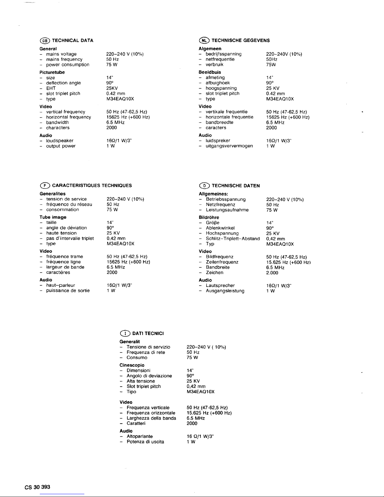
@TECHNICAL
DATA
General
-
mains voltage
220-240 v (1
0%)
-
mains frequency
50
Hz
-
power consumption
75W
Picturetube
-
size
14"
-
deflection angle
goo
- EHT 25KV
-
slot triplet pitch 0.42 mm
- type
M34EAQ10X
Video
-
vertical frequency
50
Hz (47-62,5 Hz)
-
horizontal frequency 15625 Hz
(+600Hz)
-
bandwidth 6.5 MHz
-
characters 2000
Audio
-
loudspeaker 16Qj1 W/3"
- output power
1W
([)
CARACTERISTIOUES TECHNIQUES
Generalites
- tension de service
- frequence du reseau
- consommation
Tube
image
- taille
- angle
de
deviation
-
haute tension
-
pas d'intervalle triplet
-
type
Video
-
frequence trame
-
frequence ligne
-
largeur
de bande
-
caracteres
Audio
-
haut-parleur
-
puissance de sortie
cs
30
393
220-240 v (1
0%)
50
Hz
75W
14"
goo
25
KV
0,42
mm
M34EAQ10X
50
Hz (47-62,5 Hz)
15625 Hz
(+600Hz)
6.5 MHz
2000
16Q/1 W/3"
1W
CD
DATI TECNICI
General it
- Tensione di servizio
- Frequenza di rete
- Consume
Cinescopio
- Dimensioni
- Angolo di deviazione
- Alta tensione
- Slot triplet pitch
- Tipo
Video
- Frequenza verticale
- Frequenza orizzontale
- Larghezza della banda
- Caratteri
Audio
- Altoparlante
- Potenza di uscita
@ TECHNISCHE GEGEVENS
Algemeen
-
bedrijfsspanning
-
netfrequentie
-
verbruik
Beeldbuis
-
afmeting
-
afbuighoek
-
hoogspanning
-
slot triplet pitch
-
type
Video
-
vertikale frequentie
- horizontale frequentie
-
bandbreedte
- caracters
Audio
-
luidspreker
-
uitgangsververmogen
CD
TECHNISCHE DATEN
Allgemeines:
-
Betriebsspannung
-
Netzfrequenz
-
Leistungsaufnahme
Bildrohre
-
Gr613e
-
Ablenkwinkel
-
Hochspannung
-
Schlitz-
Triplett-Abstand
-
Typ
Video
-
Bildfrequenz
-
Zeilenfrequenz
-
Bandbreite
-
Zeichen
Audio
-
Lautsprecher
-
Ausgangsleistung
220-240
v ( 1 0%)
50
Hz
75W
14"
goo
25
KV
0,42 mm
M34EAQ10X
50 Hz (47-62,5 Hz)
15.625 Hz
(+600Hz)
6.5 MHz
2000
16 Q/1 W/3"
1W
220-240V
(1
0%)
50Hz
75W
14"
goo
25
KV
0.42 mm
M34EAQ10X
50 Hz (47-62,5 Hz)
15625 Hz (
+600
Hz)
6.5 MHz
2000
16Qj1 W/3"
1W
220-240 v (1
0%)
50
Hz
75W
14"
goo
25
KV
0,42
mm
M34EAQ10X
50 Hz (47-62,5 Hz)
15.625 Hz (
+600 Hzl
6.5 MHz
2.000
16Qj1 W/3"
1W
II
,.......
L
I
.1
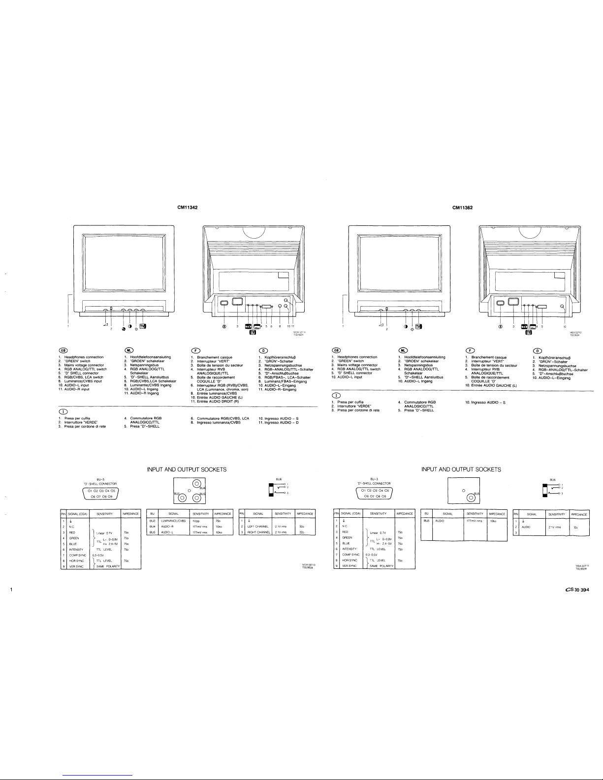
1 . Headphones connection
2.
"GREEN" switch
3.
Mains voltage connector
4.
RGB ANALOG{TTL switch
5.
"D"
SHELL connector
6.
RGB/CVBS, LCA switch
8.
Luminance{CVBS input
10.
AUDIO-L input
11.
AUDIO-A input
CD
1 . Presa per cuffia
2.
lnterruttore "VERDE"
3.
Presa per cordone
di
rete
BU-3
"D"-SHELL CONNECTOR
PIN
SIGNAL (CGA)
1
.j.
2 N C
s
6
7
8
9
RED
GREEN
BLUE
INTENSITY
COMP SYNC
HOR SYNC
VER
SYNC
01
02 03
04
OS
06 07
08 09
SENSITIVITY
}
Unea~-
0
?V
TTL 0-0,BV
H-
2,4-SV
TTL
LEVEL
0,3-0,SV
}
TTL LEVEL
SAME POLARITY
CM11342
,....... ,.......
,.......
II
I I I
I
l
1 . Hootdtelefoonaansluiting
2.
"GROEN" schakelaar
3.
Netspanningsbus
4.
RGB ANALOOG{TTL
Schakelaar
5.
"D"-SHELL Aansluitbus
6.
RGB{CVBS,LCA Schakelaar
8.
Luminantie{CVBS lngang
10.
AUDIO-L
lngang
11.
AUDIO-A
lngang
4.
Commutatore RGB
ANALOGICO{TTL
5.
Presa
"D"-SHELL
~
u
~
1\
I
1\
I
I
CJ
"'---
'---
<D
3
CD
1 . Branchement casque
2.
lnterrupteur "VERT"
3.
Boite de tension du secteur
4.
lnterrupteur RVB
ANALOGIQUE{TTL
5.
Boite de raccordement
COQUILLE "D"
=
6.
lnterrupteur RGB (RVB)/CVBS,
LCA (Luminance, chroma, son)
8.
Entree luminance{CVBS
10. Entree
AUDIO GAUCHE (L)
11. Entree
AUDIO DROIT
(R)
6.
Commutatore RGB{CVBS, LCA
8.
lngresso luminanza{CVBS
,L,......J'
~4
s 6
I
I
G.__
1\~
(~
r--
8
10
11
MOA,J2714
T02/9024
1 . Kopfhiireranschlufl
2.
"GRUN"-Schalter
3.
Netzspannungsbuchse
4.
RGB-ANALOG{TTL-Schalter
5.
"D"-Anschluflbuchse
6.
RGB/FBAS-,
LCA-Schalter
8.
Luminanz/FBAS-Eingang
10.
AUDIO-L-Eingang
11.
AUDIO-R-Eingang
10. lngresso AUDIO - S
11. lngresso AUDIO - D
INPUT
AND
OUTPUT
SOCKETS
IMPEDANCE
?So
?So
?So
75n
?So
BU
BU2
BU4
BUS
BUt§)
SIGNAL
LUMINANCE/CVBS
AUDIO-R
AUDIO-L
@U4
0
@)us
SENSITIVITY
IMPEDANCE
1Vpp
?So
177mV rms 10ko
177mV rms 10ko
BU6
c==:~
3
PIN
SIGNAL SENSITIVITY
1
.,[,.
2 LEFT CHANNEL
21Vrms
3 RIGHT CHANNEL
21V
rms
IMPEDANCE
32o
32o
MDA 02713
T02{9024
II
,...,
I I
.1
1 . Headphones connection
2.
"GREEN" switch
3.
Mains voltage connector
4.
RGB ANALOG/TTL switch
5.
"D"
SHELL connector
10.
AUDIO-L
input
CD
1. Presa per cuffia
2.
lnterruttore "VERDE"
3.
Presa per cordone di rete
BU-3
"D"-SHELL CONNECTOR
PIN
SIGNAL (CGA)
1
.j.
2 N C
RED
GREEN
BLUE
INTENSITY
COMP SYNC
HOR SYNC
VER.SYNC
01
02 03 04
OS
06
07
08 09
SENSITIVITY
}
LmeaLr
_ 0 7V
TTL
-
0-0,BV
H-
2,4-SV
TTL LEVEL
0,3-0,SV
}
TTL LEVEL
SAME POLARITY
CM11362
'-./
u
'-./
1\
I
1\
I
I
I
I I
I
CJJ
~
1---'
1L_J
,......
_,...,
I I I
I
l
1 . Hoofdteletoonaansluiting
2.
"GROEN" schakelaar
3. Netspanningsbus
4.
RGB ANALOOG{TTL
Schakelaar
5.
"D"-SHELL
Aansluitbus
10.
AUDIO-L
lngang
4.
Commutatore RGB
ANALOGICO{TTL
5.
Presa
"D"-SHELL
'---
<D
3
1.
Branchement casque
2.
lnterrupteur "VERT"
3.
Boite de tension du secteur
4.
lnterrupteur RVB
ANALOGIQUE/TTL
5.
Boite de raccordement
COQUILLE
"D"
10. Entree AUDIO GAUCHE (L)
10. lngresso
AUDIO - S
INPUT
AND
OUTPUT
SOCKETS
IMPEDANCE
·?So
?So
?So
?So
?So
BU
BUS
I
OJ
SIGNAL
SENSITIVITY
IMPEDANCE
PIN
AUDIO
177mV nms
10ko
1
2
3
r--
=
~4
s
10
MDA02712
T02;9024
1.
Kopfhiireranschlufl
2.
"GRUN"-Schalter
3.
Netzspannungsbuchse
4.
RGB-ANALOG{ITL-Schalter
5.
"D"-Anschluflbuchse
10.
AUDIO-L-Eingang
BU6
c==:~
3
SIGNAL SENSITIVITY
IMPEDANCE
.).
AUDIO
21V
rms
32o
MOA02711
T02/9024
CS30
394
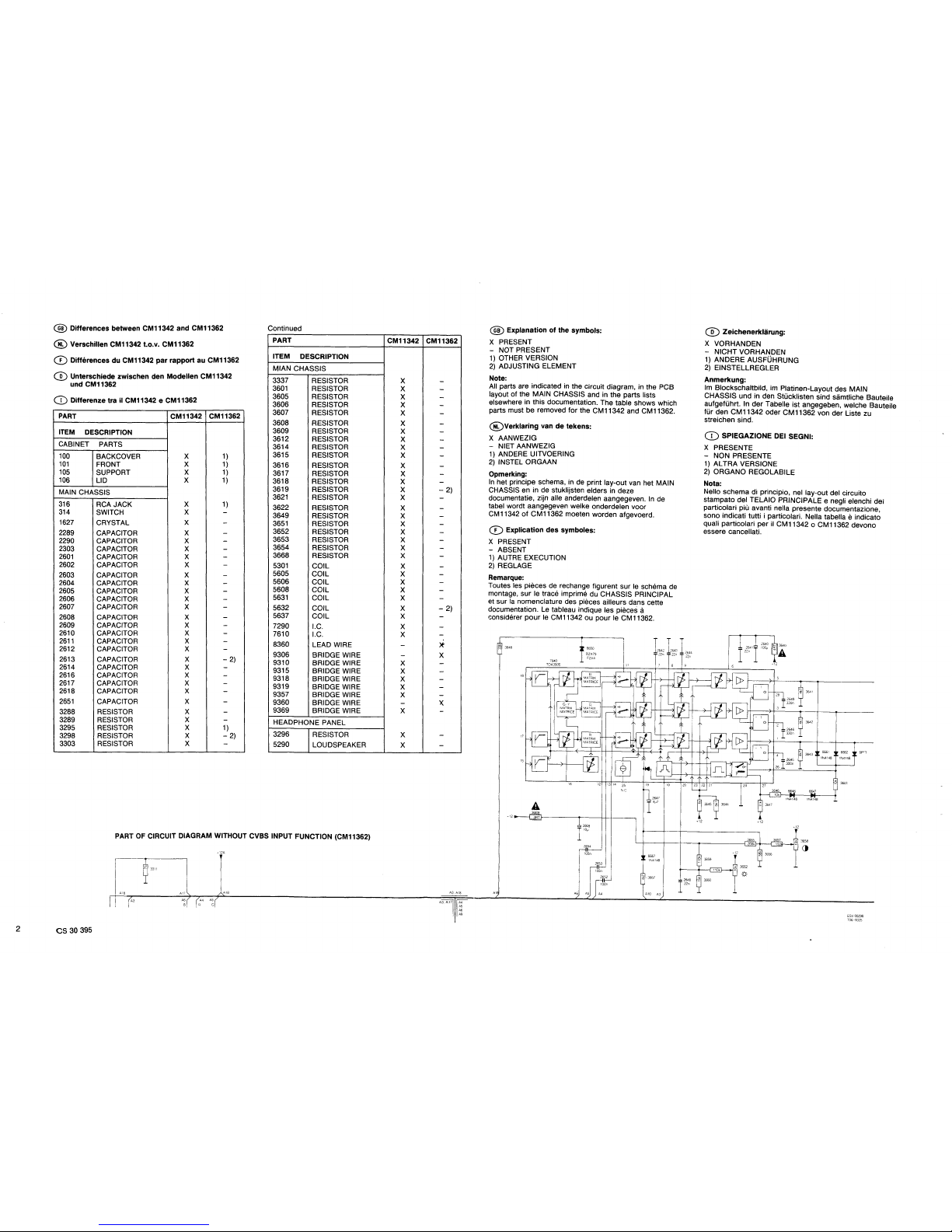
@Differences
between CM11342
and
CM11362
® Verschillen CM11342 t.o.v. CM11362
CD
Differences
du
CM11342
par
rapport
au CM11362
® Unterschiede zwischen den
Modellen
CM11342
und CM11362
CD
Differenze
trail
CM11342 e CM11362
PART
CM11342 CM11362
ITEM
DESCRIPTION
CABINET PARTS
100
101
105
106
BACKCOVER
FRONT
SUPPORT
LID
MAIN CHASSIS
316
314
1627
2289
2290
2303
2601
2602
2603
2604
2605
2606
2607
2608
2609
2610
2611
2612
2613
2614
2616
2617
2618
2651
3288
3289
3295
3298
3303
RCA JACK
SWITCH
CRYSTAL
CAPACITOR
CAPACITOR
CAPACITOR
CAPACITOR
CAPACITOR
CAPACITOR
CAPACITOR
CAPACITOR
CAPACITOR
CAPACITOR
CAPACITOR
CAPACITOR
CAPACITOR
CAPACITOR
CAPACITOR
CAPACITOR
CAPACITOR
CAPACITOR
CAPACITOR
CAPACITOR
CAPACITOR
RESISTOR
RESISTOR
RESISTOR
RESISTOR
RESISTOR
X
X
X
X
X
X
X
X
X
X
X
X
X
X
X
X
X
X
X
X
X
X
X
X
X
X
X
X
X
X
X
X
X
1)
1)
1)
1)
1)
- 2)
1)
- 2)
Continued
PART
ITEM DESCRIPTION
MIAN CHASSIS
3337 RESISTOR
3601
RESISTOR
3605 RESISTOR
3606 RESISTOR
3607 RESISTOR
3608 RESISTOR
3609 RESISTOR
3612 RESISTOR
3614 RESISTOR
3615 RESISTOR
3616 RESISTOR
3617 RESISTOR
3618 RESISTOR
3619 RESISTOR
3621
RESISTOR
3622 RESISTOR
3649 RESISTOR
3651
RESISTOR
3652 RESISTOR
3653 RESISTOR
3654 RESISTOR
3668 RESISTOR
5301
COIL
5605 COIL
5606 COIL
5608 COIL
5631
COIL
5632 COIL
5637 COIL
7290 I.C.
7610 I.C.
8360
LEAD WIRE
9306 BRIDGE WIRE
931
0 BRIDGE WIRE
9315 BRIDGE WIRE
9318 BRIDGE WIRE
9319 BRIDGE WIRE
9357 BRIDGE WIRE
9360 BRIDGE WIRE
9369 BRIDGE WIRE
HEADPHONE PANEL
3296 RESISTOR
5290 LOUDSPEAKER
PART
OF
CIRCUIT DIAGRAM WITHOUT CVBS INPUT FUNCTION (CM11362)
A3
2
cs
30 395
A17
A6
B
A18
CM11342 CM11362
X
X
X
X
X
X
X
X
X
X
X
X
X
X
X
X
X
X
X
X
X
X
X
X
X
X
X
X
X
X
X
X
X
X
X
X
X
X
X
- 2)
- 2)
>t
X
X
A3
A18
® Explanation
of
the
symbols:
X
PRESENT
- NOT PRESENT
1)
OTHER VERSION
2)
ADJUSTING ELEMENT
Note:
All parts are indicated in the circuit diagram, in the
PCB
layout of the MAIN CHASSIS and in the parts lists
elsewhere in this documentation. The table shows which
parts must be removed for the CM11342 and CM11362.
@Verklaring
van
de
tekens:
X
AANWEZIG
- NIET AANWEZIG
1)
ANDERE UITVOERING
2)
INSTEL ORGAAN
Opmerking:
In
het principe schema, in de print lay-out van het MAIN
CHASSIS
en in de stuklijsten elders in deze
documentatie, zijn aile anderdelen aangegeven.
In
de
tabel wordt aangegeven welke onderdelen voor
CM11342
of
CM11362 moeten worden afgevoerd.
Q)
Explication
des
symboles:
X
PRESENT
- ABSENT
1)
AUTRE EXECUTION
2)
REGLAGE
Remarque:
Toutes les pieces de rechange figurent sur le schema de
montage,
sur
le trace imprime du CHASSIS PRINCIPAL
et
sur
Ia
nomenclature des pieces ailleurs dans cette
documentation.
Le
tableau indique les pieces a
considerer
pour
le
CM11342 ou pour le CM11362.
~
3648
·12
A1
A10 A3
+12
®
Zeichenerklarung:
X VORHANDEN
-
NIGHT VORHANDEN
1)
ANDERE AUSF0HRUNG
2)
EINSTELLREGLER
Anmerkung:
lm Blockschaltbild, im Platinen-Layout des MAIN
CHASSIS
und in den StOcklisten sind samtliche Bauteile
aufgefUhrt. In
der
Tabelle
ist
angegeben, welche Bauteile
fur den CM 11342 oder CM 11362 von der Liste zu
streichen sind.
Q)
SPIEGAZIONE DEl SEGNI:
X PRESENTE
- NON PRESENTE
1)
AL
TRA VERSIONE
2)
ORGANO REGOLABILE
Nota:
Nello schema di principio, nel lay-out del circuito
stampato del TELAIO PRINCIPALE e negli elenchi dei
particolari
piu avanti nella presente documentazione,
sono indicati tutti i particolari. Nella tabella
e indicato
quali particolari per
il
CM11342 o CM11362 devono
essere cancellati.
·12
6662 6F"l
1N4148
ESV
00298
T06-9025
@CAUTION
1)
Safety requirements stipulate that, during repair, the
set should be restored
to
its original state and
that
parts indentical
to
the specified ones, should be
applied.
2)
For safety reasons, the parts indicated with the sign
A should be replaced by identical parts (for code
numbers see electrical parts
lists).
3)
To avoid damage to ICs and transistors, flash-over
of
the high-tension should be avoided.
4)
Be careful when performing measurements in the
high-tension section and on the picture tube.
5)
Never change parts when the set is still switched on.
6)
Safety goggles must be worn during replacement
of
the picture tube.
ELECTRICAL ADJUSTMENTS
1.
ADJUSTMENTS
ON
THE CHASSIS
1.1
+128V supply voltage (3414)
- Apply video signal to the monitor.
-
Set volume control 3295, brightness control 3662 and
contrast control 3658
to
minimum.
-
Set trimming potentiometer 3414
in
mid-position.
(This is a presetting).
- Connect
DC
voltmeter
to
junction
of
resistor 3520 and
diode 6453.
- Switch on monitor.
- With trimming potentiometer 3414 set the
DC
voltage
at junction 3524/6453 to
128V.
1.2 Horizontal synchronization (3257)
- Apply video signal
(cross-hatch
pattern) to the monitor.
- Short capacitor
2270. (This capacitor is connected
to
pin 5
of
IC
7270.)
- With trimming potentiometer 3257, adjust the picture
so that it
is
straight.
- Remove the
short-circuit
on 2270.
1.3 Picture position
General: For the following adjustments apply a video
signal
(cross-hatch
pattern) to the monitor.
1.3.1
East-west
correction (3537)
- With potentiometer 3537, make the vertical lines on
the left and
right-hand
side
of
the screen as straight
as possible.
1.3.2 Picture width (3534)
- With potentiometer 3534, set the picture width
for
14
blocks to
260 mm.
1.3.3 Horizontal picture centering (3264)
- With potentiometer 3264, set the correct horizontal
centering.
1.3.4
Vertical picture centering (3583)
- With potentiometer 3583, set the correct vertical
picture centering.
1.3.5 Picture height
(3550)
- With potentiometer 3550, set the picture height
for
1 0
blocks to 186 mm.
1.3.6.
Vertical linearity (3573)
- Adjust the correct vertical linearity with
Pre-set
potentiometer 3573. If necessary repeat 1.3.5 and
1.3.6.
1.4
Setting
of:
• VG2 (bottom knob on the line output transformer)
•
cut-off
points
of
the picture tube
(31
07, 3117 and 3127)
• white
"D"
(3671, 3680)
Set
the brightness
to
1/4
of
its range and set the
contrast to minimum.
Set the potentiometers
3107,3117,3127,3671
and
3680
in
mechanical
mid-position.
Set VG2 potentiometer
to
minimum.
Set the signal generator
in
"pur" position and
introduce the respective colours red, green and blue.
- Using potentiometers
3107, 3117 and 3127 with the
corresponding colour pattern, set the voltage on the
picture tube pins
8,
6 and
11
to 1 OOV.
- Apply a white frame and adjust the VG2 potentiometer
so
that
any colour among red, green
or
blue
becomes
visible.
-
Set the pattern generator
to
purity with
the
colour that
was
first visible.
- Reset
VG2 potentiometer
to
just
visible light.
- Adjust the
two
remaining colours with
their
corresponding purity colour
to
the same light
output
using potentiometers
31
07, 3117
or
3127.
- Return the signal generator
to
white
frame
and adjust
the potentiometers
3107,3117
and 3127
so
that
an
optimum background colour is obtained.
- Using potentiometers 3671 and
3680 (with white
frame) adjust the background colour
so
that
at
minimum brightness and maximum brightness the
background colour is the same.
1.5 Focusing (top knob
on
line output transformer)
- Apply white pattern to monitor.
- Adjust focusing so that the picture
at
2/3
of
the
diagonal lines (counting from center
to
four
corners)
of
the displayed screen is as sharp as
possible.
1.6 Subcarrier oscillator (2613)
- Apply colour bar pattern
to
monitor.
- Connect
470Q resistor between point
11
of
IC
761
0
and earth.
- Adjust 2613 so that the colour picture
on
the screen is
stationary.
- Remove the
470Q resistor.
1.7 PAL delay line (3619, 5632)
-
Apply
OEM pattern from a pattern
generator
to
the
monitor.
Set brightness control 3662,
contrast
control
3658 and
colour
saturation control 3654 to
3/4
of
the
range.
Adjust 3619
so
that the "venetian blinds"
in
the
third
bar
disappear.
Then adjust 5632 until the
"venetian
binds"
in
the first
and fourth
bar
disappear.
Readjust 3619 as described above.
1.8 Chrominance suppression
(5605)
- Apply colour bar pattern to the monitor.
- Connect oscilloscope
to
pin 15
of
IC 7540.
- Set 5605
so
that the chrominance
sig~al
is
minimum.
(The chrominance signal
is
superimposed
on the
grey
steps
of
the luminance signal).
1.9 Audio balance (3298)
- Apply sinusoidal signal
of
177mVrms
11
K
tlz)
to
both
audio inputs LfR.
-
Set volume control
in
mid-position.
- Replace the
two
loudspeakers with a
160
resistor.
-
Set 3298 so
that
the
output
level on
b~th
16Q
resistors is the same.
cs
30
396
2.
PICTURE SETTINGS
Remarks:
-
The
following adjustments only apply to monitors
which are fitted with a replaceable deflection unit.
-
In
case
of
combi tube replacement, no picture settings
are required because it has been done by factory
already
- The colour purity and convergence adjustments
described hereafter need only to
be
carried out if a
completely new setting is required or if a new picture
tube has been fitted.
In
other cases,
for
example after
replacing the deflection unit, it
will not usually be
necessary to remove the rubber wedges
(G
in
figure
3).
Corrections by means
of
the
multi-pole
unit will
then suffice.
- Focusing adjustment described
in
item 1
.5
must be
done
prior
to picture settings.
2.1
Colour purity, see figure 3
- Unscrew the fixing screw
"F"
on the deflection unit.
Move the deflection unit and remove the three rubber
wedges
"G".
Move the deflection unit forward as far as possible
against
the
glass of the picture tube cone and tighten
fixing
screw
"F"
so that the deflection unit can only
be
shifted slightly.
Place the
multi-pole
unit
in
the position drawn: tighten
screw
"A" and turn locking ring "B" anticlockwise.
Position
the
monitor to face east or west and switch it
on. Apply a
cross-hatch
pattern and set the
brightness control to maximum.
Allow the monitor to
warm up
for
ten minutes.
Adjust the static convergence using tags
"C" and
"D"
(if necessary, refer to point 2.2.).
Turn 3583 for the vertical centering to its
mid-position.
Switch off the green and blue guns
by
disconnecting resistors 3122 and 3112.
By
turning the colour purity rings with the
"E"
tags, the
vertical
red
bar is brought as close as possible to the
center
of
the
screen, while the central horizontal line
should be as straight as possible.
Apply a
white
pattern signal and check that the red
bar is in
fact
in the center
of
the screen. If not, switch
on
the
cross-hatch
pattern again and move the red
bar
in
the right direction, ensuring that the picture
does
not
move
too much
in
the vertical direction.
Apply the white pattern signal and move the deflection
unit until
the
whole picture surface is uniformly red.
Switch
on
the green and blue guns. There may be no
colour
patches
in the white picture now obtained. If
there are, a minor correction can be made by turning
the
colour
purity rings
"E"
slightly and{or moving the
deflection unit slightly.
Tighten
screw
"F" securely.
Adjust
the
vertical centering with 3583.
Proceed
to
the static and then the dynamic
convergence setting.
2.2 Static
convergence,
see figure 3
- Apply a
cross-hatch
pattern and allow the monitor to
warm up
for
ten minutes.
- Switch
off
the green gun by disconnecting resistor
3122 and
turn
locking ring "B" anticlockwise.
- By
turning
the
four-pole
rings with the "C" tags the
red and
blue
cross-hatch
patterns are placed on top
of each
other
in the center of the screen.
- Switch
on
the green gun by connecting resistor 3122
back
to
its
orginal position and switch
off
the blue gun
by
disconnecting
3112.
- By
turning
the
six-pole
rings with the "D" tags the red
and
green
patterns are placed on top
of
each other
in
the
center
of
the screen.
- Switch
on
the blue gun by connecting resistor 3112
back
to
its
orginal position and tighten ring "B".
cs
30
397
2.3 Dynamic
convergence
Remark:
The dynamic convergence is achieved by tilting the
deflection unit
vertically and horizontally.
In
order
to
fix
the deflection unit in the right position, three rubber
wedges are fitted between the glass
of
the picture tube
cone and the deflection unit, as shown
in
fig. 4d
or
5d.
Two
wedge thicknesses are available, one 7 mm thick,
code number 4822 462 40356 and the other
11
mm thick,
code number 4822 462 40357.
- First check the colour purity and the static
convergence.
- Apply a
cross-hatch
pattern and switch
off
the green
gun by disconnecting resistor 3122.
- Eliminate the crossing
of
the central horizontal blue
and red line and the crossing
of
the central vertical
blue and red line by
vertically tilting the deflection unit.
If the deflection unit is
in
the correct position, then
place rubber wedge
(D,
without removing the paper
strip, at the
top
(figure 4a)
or
at the bottom (figure
5a).
Figure 4a applies when the unit is tilted upwards and
figure 5a applies when the unit is tilted downwards.
- Through the horizontal tilting
of
the deflection unit,
both the horizontal blue and red lines in the upper
and
lower halves
of
the picture and the vertical blue and
red lines on the left and
right-hand
side
of
the picture
are placed on
top
of
each other.
If the deflection unit is in the correct position, then
place the wedges
® and @ , remove the paper
strips and firmly press the adhesive side
of
these
wedges against the glass
of
the picture tube as
shown
in
figure 4b
or
5b.
Now place wedge
@ as shown in figure 4c
or
5c,remove the paper strip and firmly press the
adhesive side of this wedge against the glass
of
the
picture tube cone.
Remove wedge
CD
so that the situation according to
figure 4d or 5d arises.
- Switch on the green gun by connecting resistor 3122
back to its original position.
@ WAARSCHUWINGEN
1)
Veiligheidsbepalingen vereisen, dat het apparaat bij
reparaties
in
zijn oorspronkelijke toestand
wordt
teruggebracht
en
dat onderdelen, identiek aan de
gespecifeerde worden toegepast.
2)
Onderdelen voorzien van het teken A dienen om
veiligheidsredenen vervangen te worden
door
identieke onderdelen.
(Voor kodenummers zie elektrische stuklijsten).
3)
Om
beschadigingen van IC's en transistoren te
voorkomen moet iedere
overslag van de
hoogspanning worden vermeden.
4)
Wees voorzichtig tijdens het meten
in
het hoog
spannings
gedeelte en aan de beeldbuis.
5)
Verwissel nooit onderdelen terwijl het apparaat is
ingeschakeld.
6)
Tijdens het vervangen van de beeldbuis
wordt
het
dragen van een
veiligheidsbril voorgeschreven.
ELECTRISCHE INSTELLINGEN
1.
INSTELLINGEN
OP
HET CHASSIS
1.1
+128 V voedingsspanning (3414)
- Videosignaal aan het apparaat toevoeren.
Volumeregelaar 3295, helderheidsregelaar 3662 en
contrastregelaar 3658 op minimum.
Plaats instelpotentiometer 3414
in
middenpositie. (Dit
is een
voorinstelling)
Gelijkspanningsmeter aansluiten op knooppunt van
weerstand
3520
en
diode 6453.
Apparaat
inschakelen.
Met instelpotentiometer 3414 de gelijkspanning
op
knooppunt 3520/6453 instellen op 128
V.
1.2 Horizontale synchronisatie
- Videosignaal (ruitpatroon) aan het apparaat toevoeren.
- Condensator
2270 kortsluiten. (Deze condensator is
op pin 5 van
IC7270 aangesloten.)
- Met instelpotentiometer 3257 het beeld zodanig
instellen dat het rechtop staat.
- Verwijder de
kortsluiting over 2270.
1.3 Beeldpositie instellingen
Algemeen: Bij onderstaande instellingen een videosignaal
(ruitpatroon)
aan
het apparaat toevoeren.
1.3.1. Oost-west correctie (3534)
- Met potentiometer 3537 de verticale lijnen links en
rechts op het scherm zo recht
mogelijk maken.
1.3.2 Beeldbreedte (3534)
- Met potentiometer 3534 de beeldbreedte voor "14
blokken" instellen
op
260 mm.
1.3.3 Horizontale beeldcentreering (3264)
- Met potentiometer 3264
de
correcte horizontale
centrering instellen.
1.3.4 Verticale beeldcentrering (3583)
- Met potentiometer 3583 de optimale verticale
beeldcentrering instellen.
1.3.5 Beeldhoogte (3550)
- Met potentiometer 3550 de beeldhoogte voor
"1
0
blokken" instellen
op 186 mm.
1.3.6 Vertical lineariteit (3573)
-
De
correcte verticale lineariteit instellen met
instelpotentiometer 3573 zonodig,
herhaal de
instellngen 1.3.5
en
1.3.6.
1.4 lnstellingen
van:
• VG2 (onderste knopje
op
de lijntrafo)
•
Afknijppunten van de beeldbuis (3107.3117
en
3127)
• Wit
"D"
(3671, 3680)
Stel
de helderheid
in
op
1/4
van zijn bereik en stel de
contrast
in
op minimum.
let
de potmeters
3107,3117,3127
3671
en
3680 op
mech. middenstand.
-
Regel VG2 potentiometer
op
minumum.
-
let
de signaal generator op stand "pur" en voer de
respectievelijke
kleuren rood -
groen
- blauw in.
-
Stel met behulp van de potmeters 3107, 3117
en
3127
met het bijbehorende
kleurpatroon,
de
spanning
op
de
beeldbuispinnen
8, 6 en
11
in
op
100
V.
-
Voer
een wit raster toe,
en
regel de VG2
potentiometer zodanig op zodat een van
de
kleuren
rood, groen
of
blauw juist zichtbaar wordt.
-
Zet
de patroongenerator op purity
met
de kleur die
zonet
als eerste zichtbaar was.
-
De
VG2 potentiometer opnieuw instellen
op
net
zichtbaar
Iicht.
- De overgebleven 2 kleuren met hun bijbehorende
purity
kleur bijregelen met de potmeters 3107, 3117
of
3127
op
dezelfde hoeveelheid Iicht opbrengst.
-
Zet
de signaal generator terug
op
wit
raster
en
regel
de potmeters 3107, 3117
en
3127 zodanig bij
dater
een optimale achtergrond kleur ontstaat.
-
Regel met behulp van potmeters 3671
en
3680 (met
wit
raster), de achtergrondkleur zodanig in dat bij
minimum
helderheid
en
maximum helderheid
de
achtergrondkleur hetzelfde is.
1.5 Focussering (bovenste knopje op lijntrafo)
- Witpatroon a
an
apparaat toevoeren.
- Focussering zodanig
instellen
dat
het beeld bij 2/3
van
de
diagonale lijnen (geteld vanaf het centrum naar
de
4 hoeken) van het weergegeven beeld
zo
scherp
mogelijk is
1.6 Hulposcillator (2613)
- Kleurenbalkenpatroon
aan
apparaat
toe~oren.
- Weerstand van 4 70Q aansluiten tussen punt
11
van
IC761 0 en massa.
- 2613 zodanig
instellen dat het kleurenbeeld op het
scherm
stilstaat.
- Verwijder de weerstand van 470!1.
1.7 PAL-delay line (3619, 5632)
- OEM patroon van een patroongenerator a
an
het
apparaat toevoeren.
-
Zet
de helderheidsregelaar 3662,
de
contrastregelaar
3658 en de
kleurverzadigingsregelaar 3654 op 3/4
van
het bereik.
-
Regel 3619 zodanig af dat de "venetian
~li
nds"
in
de
3e balk verdwijnen.
-
Regel vervolgens 5632
at
todat de "venetian blinds" in
de 1 e en 4e
balk verdwijnen.
-
Regel 3619 opnieuw af zoals hierboven omschreven.
1.8 Chrominantieonderdrukking (5605)
- Kleurenbalkenpatroon
aan
apparaat
toe~oeren.
- Osciloscope aansluiten op pin 15 van IC7640.
- 5605 zodanig instellen dat het
chromina~ti
esignaal
minimaal
is. (Het chrominantiesignaal zit
gesuperponeerd
op
de grijstrappen van
~et
luminantie
signaal.
1.9 Audiobalans (3298)
- Sinussignaal van 177mVrms (1KHz)
toe~oeren
aan
beide audioingangen L/R.
-
Volume regelaar
in
de midden positie.
- Vervang de beide
luidsprekers
door
eenweerstand
van 16!1.
- 3298 zodanig instellen dat het
uitgangsnveau
op
beide
16Q
weerstanden gelijk is.
cs 30
398
 Loading...