

Page 1

Instructions for Use
IntelliVue Cableless
Measurements
CL SpO2 Pod – CL NBP Pod –
CL Respiration Pod
Release D.00
Patient Monitoring
Page 2

Page 3

1Table of Contents
1 Introduction and Basic Operation 5
Safety Information 6
Security Information 8
Introducing the IntelliVue Cableless Measurements 10
2 IntelliVue CL SpO2 Pod 13
General Operation of the SpO2 Pod 13
Connection with Host Systems 20
Monitoring SpO2 28
Alarms 34
Local Attended Monitoring 43
SpO2 Default Settings 49
Integrated Battery Handling 50
Accessories 52
Maintenance and Troubleshooting 53
3 IntelliVue CL NBP Pod 55
General Operation of the NBP Pod 55
Connection with Host Systems 62
Monitoring NBP 69
Alarms 77
Local Attended Monitoring 86
NBP Default Settings 91
Integrated Battery Handling 92
Accessories 93
Maintenance and Troubleshooting 97
4 IntelliVue CL Respiration Pod 99
General Operation of the Respiration Pod 99
Connection with Host Systems 100
Monitoring Respiration 104
Technical Alarms (INOPs) 108
Respiration Default Settings 109
Integrated Battery Handling 110
Accessories 111
Maintenance and Troubleshooting 112
5 Cableless Measurement Auxiliary Devices 113
IntelliVue CL Transmitter and IntelliVue CL Hotspot 113
IntelliVue CL Transmitter Base Station 117
3
Page 4

IntelliVue CL Charging Station 118
Maintenance and Troubleshooting 119
6 Care and Cleaning 121
General Points 121
Cleaning and Disinfecting the IntelliVue Cableless Measurement Devices 122
Disposing of the IntelliVue Cableless Measurement Devices 123
7 Specifications 125
Indications for Use 125
Compatible Medical Devices 127
Symbols 127
Manufacturer's Information 129
Regulatory and Safety Specifications 129
EMC and Radio Regulatory Compliance 130
Safety and Performance Tests 132
Electromagnetic Compatibility (EMC) 132
Accessories Compliant with EMC Standards 133
Electrosurgery Interference/Defibrillation 133
IntelliVue CL SpO2 Pod Specifications 133
IntelliVue CL NBP Pod Specifications 135
IntelliVue CL Respiration Pod Specifications 138
Alarm Specifications for CL NBP, CL SpO2 and CL Resp Pod 140
Telemetry Device Battery Runtime Specifications 141
IntelliVue CL Transmitter Specifications 141
IntelliVue CL Transmitter Base Station Specifications 143
IntelliVue CL Hotspot Specifications 144
Index 147
4
Page 5

1Introduction and Basic Operation
These Instructions for Use are for clinical professionals using the IntelliVue Cableless Measurements and
their specified compatible accessories.
IntelliVue Cableless Measurements refers to the IntelliVue Cableless Measurements product family
consisting of the IntelliVue CL SpO
Respiration Pod (865218) with their accessories. Also included are the auxiliary devices: the IntelliVue CL
Charging Station (865220), IntelliVue CL Transmitter (865221), IntelliVue CL Transmitter Base Station
(865237) and IntelliVue CL Hotspot (865222).
The IntelliVue Cableless Measurements are used for monitoring and recording arterial oxygen saturation,
pulse rate, noninvasive blood pressure and respiration rate of adult and pediatric patients.
Familiarize yourself with all instructions including warnings and cautions, and attend one of the training
courses, before starting to make measurements with patients. Read and keep the Instructions for Use that
come with any accessories, as these contain important information about care and cleaning that is not
repeated here.
When using the IntelliVue Cableless Measurements with an IntelliVue Patient Monitor, an Avalon Fetal
Monitor, a telemetry system or IntelliVue GuardianSoftware, refer to and adhere to all warnings in the
Instructions for Use of the respective device or software.
This guide may contain descriptions of functionality and features that are not implemented in the
equipment currently shipped to Japan and/or of products that are not currently sold in Japan due to
limitations and restrictions under the applicable local laws and regulations in Japan. Please contact your local
sales representative and/or Philips Customer Support for details.
In these Instructions for Use:
•A warning alerts you to a potential serious outcome, adverse event or safety hazard. Failure to observe
a warning may result in death or serious injury to the user or patient.
•A caution alerts you to where special care is necessary for the safe and effective use of the product.
Failure to observe a caution may result in minor or moderate personal injury or damage to the product
or other property, and possibly in a remote risk of more serious injury.
Pod (865215), IntelliVue CL NBP Pod (865216) and IntelliVue CL
2
1
Display refers to the physical display of the Cableless Measurement Device. Screen refers to everything
you see on the IntelliVue Cableless Measurement's display, such as measurement values, patient data and so
forth.
IntelliVue CL Transmitter/WLAN functionality may not be available in all countries.
5
Page 6

1 Introduction and Basic Operation
Safety Information
Use Environment
WARNING
• If a patient being monitored by Cableless Measurement Devices moves out of range of the patient
monitor, the measurements are not transmitted to the patient monitor or the Information Center. Keep
the patient monitor with the patient during transport.
• Always make sure that the applied pod is assigned to the correct patient.
Electrical Hazards
WARNING
• Electrical shock hazard: Do not open the device housing. Refer all servicing to qualified service
personnel.
• Always use the supplied power cord with the grounded mains plug to connect the charging station to a
grounded AC mains socket. Never adapt the mains plug from the charging station to fit an ungrounded
AC mains socket.
• Do not use AC mains extension cords or multiple portable socket outlets. If a multiple portable socket
outlet without an approved isolation transformer is used, the interruption of its protective grounding
may result in enclosure leakage currents equal to the sum of the individual ground leakage currents, so
exceeding allowable limits.
• Do not connect any devices that are not supported as part of a system.
Radiofrequency Interference
WARNING
• Short Range Radio connections are subject to interruption due to interference from other radio sources
in the vicinity, including microwaves, bluetooth devices, WLAN devices (802.11b,g,n) and cordless
phones. Depending on the strength and duration of the interference, the interruption may occur for an
extended period. A loss of connection, due to moving out-of-range, interference, or for other reasons,
is indicated with a
SpO₂ Disconnect
important, refer to the Configuration Guide for details.
or cl Resp Disconnect INOP at the host monitor. Correct channel configuration is
Battery Handling
WARNING
• Do not crush or puncture - mechanical abuse can lead to internal damage and internal short circuits
which may not be visible externally.
• Do not incinerate the devices or expose them to temperatures above 60°C (140°F).
No Host Monitoring INOP on the NBP or SpO
Pods, or a cl NBP Disconnect, cl
2
6
Page 7

Accessories
Maintenance
1 Introduction and Basic Operation
WARNING
• Reuse: Never reuse single-patient sensors, accessories and so forth that are intended for single use, or
single patient use only. Reuse may compromise device functionality and system performance and cause
a potential hazard, in particular with regard to cross-contamination.
• Philips’ approval: Use only Philips-approved accessories. Using non-Philips-approved accessories may
compromise device functionality and system performance and cause a potential hazard.
• Using accessories other than those specified may result in increased electromagnetic emission or
decreased electromagnetic immunity of the IntelliVue Cableless Measurement Devices.
WARNING
• Schedule: Failure on the part of the responsible individual hospital or institution employing the use of
this equipment to implement a satisfactory maintenance schedule may cause undue equipment failure
and possible health hazards.
• Contact: If you discover a problem with any of the equipment, contact your service personnel, Philips,
or your authorized supplier.
• If the IntelliVue Cableless Measurement Device is mechanically damaged, or if it is not working
properly, do not use it for any monitoring procedure on a patient, contact your service personnel.
Care, Cleaning and Disposal
WARNING
• If you spill liquid on the equipment, or if the equipment is accidentally immersed in liquid, contact your
service personnel or Philips service engineer. Do not operate the equipment before it has been tested
and approved for further use.
• Do not use flammable agents for disinfecting the equipment in an oxygen-enriched environment, as
this might lead to sudden ignition of vapors, resulting in injury to the patient or staff.
• To avoid contaminating or infecting personnel, the environment or other equipment, make sure you
disinfect and decontaminate the IntelliVue Cableless Measurement Devices appropriately before
disposing of it in accordance with your country's laws for equipment containing electrical and electronic
parts. For disposal of parts and accessories, where not otherwise specified, follow local regulations
regarding disposal of hospital waste.
7
Page 8

1 Introduction and Basic Operation
Security Information
Protecting Personal Information
Protecting personal health information is a primary component of a security strategy. Each facility using the
devices must provide the protective means necessary to safeguard personal information consistent with
country laws and regulations, and consistent with the facility’s policies for managing this information.
Protection can only be realized if you implement a comprehensive, multi-layered strategy (including policies,
processes, and technologies) to protect information and systems from external and internal threats.
As per their intended use, the devices operate in the patient vicinity and contain personal and sensitive
patient data. They also include controls to allow you to adapt the devices to the patient's care model.
To ensure the patient's safety and protect their personal health information you need a security concept that
includes:
• Physical security access measures - access to the devices must be limited to authorized users. It is
essential that you consider physical security measures to ensure that unauthorized users cannot gain
access.
• Operational security measures - for example, ensuring that devices are powered off after monitoring
in order to remove patient data from the device.
• Procedural security measures - for example, assigning only staff with a specific role the right to use
the devices.
In addition, any security concept must consider the requirements of local country laws and regulations.
Always consider data security aspects of the network topology and configuration when connecting devices
to shared networks. Your medical facility is responsible for the security of the network, where sensitive
patient data from the monitor may be transferred.
When a device is returned for repair, disposed of, or removed from your medical facility for other reasons,
always ensure that all patient data is removed from the device by powering it off.
NOTE
Log files generated by the devices are used for system troubleshooting and do not contain protected health
data.
About HIPAA Rules
If applicable, your facility’s security strategy should include the standards set forth in the Health Insurance
Portability and Accountability Act of 1996 (HIPAA), introduced by the United States Department of Health
and Human Services. You should consider both the security and the privacy rules and the HITECH Act
when designing policies and procedures. For more information, please visit:
http://www.hhs.gov/ocr/privacy/
About the EU Directives
If applicable, your facility’s security strategy should include the practices set forth in the Directive on the
protection of individuals with regard to the processing of personal data and on the free movement of such
data (Directive 95/46/EC of the European Parliament and of the Council of 24 October 1995). In addition,
your facility should also take into account any additional applicable regulation or statutory requirement.
Philips Product Security Policy Statement
Additional security and privacy information can be found on the Philips product security web site at:
http://www.usa.philips.com/healthcare/about/customer-support/product-security
8
Page 9

1 Introduction and Basic Operation
Manufacturer Disclosure Statement for Medical Device Security – MDS2
You can view the Manufacturer Disclosure Statements for Medical Device Security (MDS2) for specific
devices at:
http://www.usa.philips.com/healthcare/about/customer-support/product-security
9
Page 10

1 Introduction and Basic Operation
Introducing the IntelliVue Cableless Measurements
The IntelliVue Cableless Measurement Devices provide measurement values and communicate them to
other system components using a wireless short range radio (SRR) interface.
Introduction
IntelliVue CL SpO2 Pod
The IntelliVue CL SpO
cableless Pulse Oximetry measuring device.
Pod is a battery powered,
2
IntelliVue CL NBP Pod
The IntelliVue CL NBP Pod is a battery powered,
cableless, noninvasive blood pressure (NBP)
measuring device.
10
IntelliVue CL Respiration Pod
The IntelliVue CL Respiration Pod is a battery powered, cableless device for measuring respiration rate
and, optionally, pulse. It also provides basic information about patient posture and activity.
Page 11

Basic Operation
IntelliVue CL SpO2 Pod and IntelliVue CL NBP Pod
1 Introduction and Basic Operation
The IntelliVue CL SpO
Monitors MP5/MP5SC/MP5T, MP2/X2, IntelliVue Telemetry System Transceivers TRx4841A/
TRx4851A, MX40 wearable patient monitors, Avalon Fetal Monitors, and IntelliVue GuardianSoftware.
Both devices have an LC display and three keys for basic operation:
IntelliVue CL Respiration Pod
The IntelliVue CL Respiration Pod can be used together with IntelliVue Patient Monitors MP5/MP5SC/
MP5T, MP2/X2, or IntelliVue GuardianSoftware. The device has one multi-color LED for status display
and one hardkey for basic operation, e.g. to start a measurement.
Pod and the IntelliVue CL NBP Pod can be used together with IntelliVue Patient
2
1 Integrated monochrome LC display
2 Hardkeys
3 Measurement identifier
1 Multi-color LED
2 Measurement identifier
3 Hardkey
4 Indication for built-in RFID tag
11
Page 12

1 Introduction and Basic Operation
12
Page 13

2IntelliVue CL SpO2 Pod
The IntelliVue CL SpO2 Pod is a wrist-worn device; you need a Mobile CL SpO2 Cradle to hold the sensor
connector in place and a wristband to fix the cradle to a patient's arm.
2
Specialized single-patient SpO
regarding the complete set of single-patient supplies, cradle, wristband and sensors, refer to “IntelliVue CL
SpO2 Pod Accessories” on page 52.
sensors are available for use with the IntelliVue CL SpO2 Pod. For details
2
General Operation of the SpO2 Pod
The following sections describe operation on the SpO2 Pod itself. For operation from a patient monitor, see
“Controls Available with a Patient Monitor” on page 25. For operation from an Information Center via a
telemetry system, see “Controls Available with a Telemetry Device” on page 26. For operation with
IntelliVue GuardianSoftware, see “Controls Available with GuardianSoftware” on page 27.
The SpO
the screen. These are used to activate and navigate through the on-screen menus and to select individual
items. The typical operator's position is such that everything on the device's display can be read clearly and
easily.
Switching the Device On
The first time an SpO2 Pod is used, or after the device has been powered off for storage, place it on the
IntelliVue CL Charging Station. This will automatically switch the device on.
If the SpO2 Pod has only been switched off temporarily (see “Switching the Device Off” on page 17), press
any hardkey to turn the device on again.
When an SpO
little later the low-activity screen will be displayed.
Pod has three hardkeys for basic operation and a set of configurable SmartKeys which appear on
2
Pod is not operated, it will automatically switch off the screen lighting after a short time. A
2
13
Page 14
2 IntelliVue CL SpO2 Pod
Screen Layout
There are three variations of the Main Screen layout depending on the Alarm status and the general activity
level.
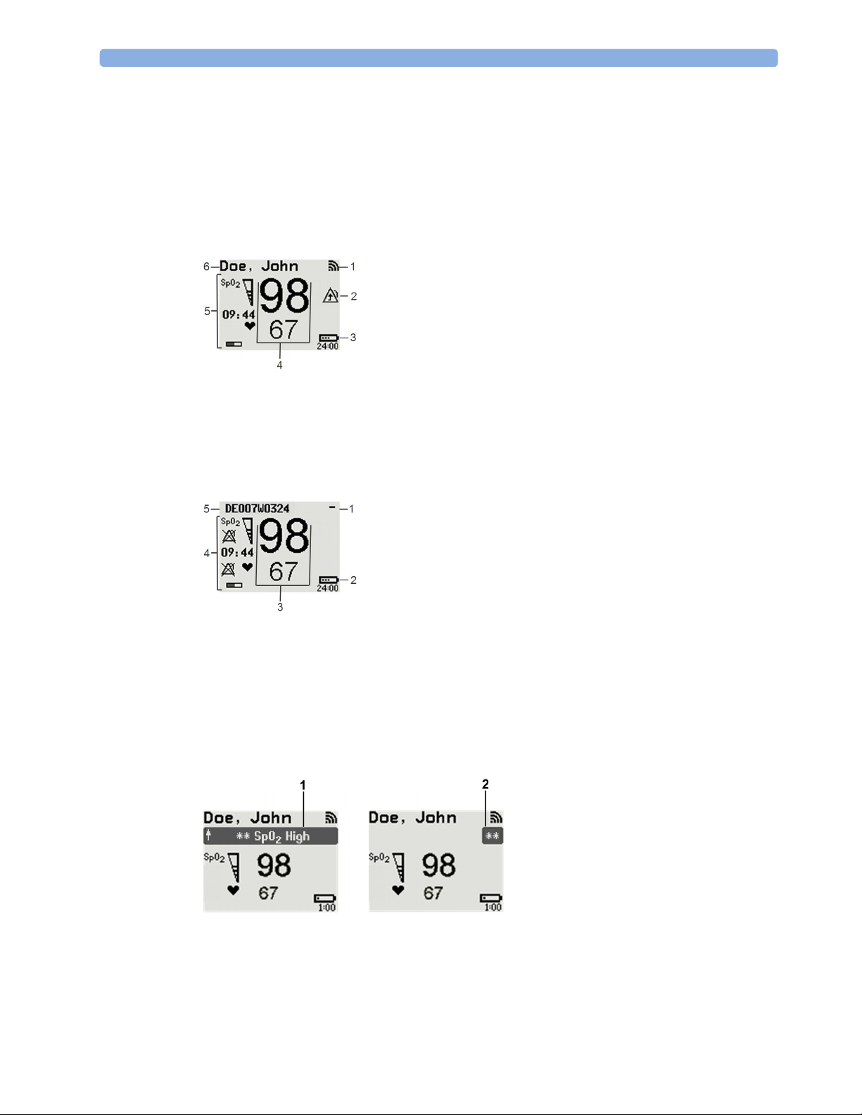
Standard Layout
When assigned to a monitor, telemetry device or a patient in GuardianSoftware:
1 Connection status indicator
2 Indicator that alarming capability has been transferred to
the host (to the monitor or, for the telemetry device, to
the Information Center). No patient alarms will be
announced on the Cableless Measurement Device.
3 Battery indicator
4 Measurement values
5 Measurement-related symbols (see the “Monitoring
SpO2” section for details)
6 Patient identification
Alarm Layout
When not assigned to a monitor or telemetry device:
1 Connection status indicator
2 Battery indicator
3 Measurement values
4 Measurement-related symbols (see the “Monitoring
SpO2” section for details). The Alarms Off symbols
indicate that no physiological alarms are available from
the Cableless Measurement Devices when not assigned
to a host.
5 Cableless Measurement Device equipment label
If an alarm occurs the full alarm message appears at the top of the screen. After the alarm message has been
silenced the alarm indicator is shown as a symbol on the right side of the screen.
1 Full length alarm message
2 Alarm indicator
14
Page 15

Low-Activity Screen
If the Cableless Measurement Device has not been operated for a while, the screen lighting will switch itself
off and a little later the screen will switch to a pre-configured "low-activity" screen.
When a Cableless Measurement Device Cannot be Activated
If you cannot activate a device by pressing a key, place it on the IntelliVue CL Charging Station. The device
becomes active. Check the battery status. If necessary, leave the device on the charger until the battery is
fully charged.
Using the Hardkeys
The IntelliVue Cableless Measurement Devices have three hardkeys: ◄, , ►.
Use ◄ and ► to navigate through SmartKeys and menus and to select items or to silence alarms.
The three hardkeys also have an additional function when the key is held down for a couple of seconds:
◄ opens the Add To screen to assign a device (or to unassign it when it is already assigned)
2 IntelliVue CL SpO2 Pod
opens the SmartKeys menu
► returns to the Main Screen. If already on the Main Screen, it locks the keys and a lock symbol
appears on the screen above the battery symbol. If keys are already locked, it unlocks the keys and
the lock symbol disappears
Using the SmartKeys
A SmartKey is a graphical key which appears on the screen and gives you fast access to functions.
SmartKeys Menu
Press the hardkey (without any screen element highlighted) to get to the SmartKeys menu.
Use the ◄ and ► hardkeys to move along the row of SmartKeys. The highlighted SmartKey is displayed in
full above the row of SmartKeys. When you use the ◄ or ► hardkey at the end of the row, an
appears and then with further presses you move on to the next page of SmartKeys. To leave the SmartKeys
menu you can use the
Screen.
When the required SmartKey is highlighted, press the key to activate the corresponding function.
To get to the next page of the SmartKeys menu, highlight the rightmost SmartKey then press the ► key.
Exit screen
Exit screen or press the ► hardkey for a couple of seconds to return to the Main
15
Page 16
2 IntelliVue CL SpO2 Pod
List of Available SmartKeys
SmartKey Text Labels
Main Setup
start an SpO
set the SpO
Add/Remove device
Battery menu
enter
Profiles menu
enter
measurement
2
mode
2
change Screen
put device in standby mode (or power off when pressed for more than two
seconds)
Patient menu
enter
enters the
Alarms menu to access: Alarm Messages, Alarm Limits, Alarms On/
Off/Pause, Alarm Volume.
16
Change alarm volume
Change pulse tone volume
Page 17

Using the Main Setup Menu
In addition to the hardkeys and SmartKeys for the most needed functions, the Main Setup menu gets you to
all settings that can be adjusted for the respective device. Select the
menu.
Setup
Main Setup
SpO₂
Pulse
Alarms
Patient
Equipment
User Interface
Standby
Profiles
Operating Modes
Date, Time
Battery
Revisions
2 IntelliVue CL SpO2 Pod
Main Setup SmartKey to get to the Main
Switching the Device Off
To put the device in standby mode, select the Standby SmartKey, then Confirm.
If you keep
•
Standby pressed for more than two seconds, you can choose between Standby or Power Off.
Standby means that the display is switched off and the measurements are disabled. Use this option if
your device is not used temporarily. Press any hardkey to turn the device on again.
•
Power Off means that the device is switched off completely and can only be switched on again by
putting it on a charger. Use this option when the device is not used for a longer time or prepared for
storage or shipping.
Auto Standby and Auto Power Off
The device can be configured to automatically go into standby mode after a configurable time span of
inactivity. When in standby mode, the device can be automatically powered off after a configurable time
span. See the IntelliVue Cableless Measurements Configuration Guide for details on how to configure these
settings.
Operating Modes
Your device has four operating modes. Some are passcode protected.
• Monitoring Mode: This is the normal, every day working mode that you use for making
measurements. You can change elements such as measurement modes, patient category and so forth.
When you remove the patient from the device, these elements return to their default values. Changes
can be stored permanently only in Configuration Mode. You may see items, such as some menu
options, that are visible but 'grayed out' so that you can neither select nor change them. These are
present for your information only and can be changed only in Configuration Mode.
• Demonstration Mode: Passcode protected, this is for demonstration purposes only. You must not
change into Demonstration Mode during monitoring.
• Configuration Mode: Passcode protected, this mode is for personnel trained in configuration tasks.
These tasks are described in the Configuration Guide. During installation the Cableless Measurement
Device is configured for use in your environment. This configuration defines the default settings you
work with when you switch on.
17
Page 18

2 IntelliVue CL SpO2 Pod
• Service Mode: Passcode protected, this is for trained service personnel.
When you switch the device on, it starts up in monitoring mode. To change to a different mode:
1 Use the
2 Select
Main Setup SmartKey to get to the Main Setup menu.
Operating Modes and choose the mode you require.
Using the Patient Menu
The Patient menu allows you to see patient demographics information and to remove a patient from a
device. Patient Demographic information is only displayed if the Cableless Measurement Device is assigned
to a patient monitor or GuardianSoftware.
changed at the Cableless Measurement Device, but only when the device is not assigned to a patient
monitor or telemetry device.
Displaying the Patient Menu
To display the Patient menu,
• select the
• select the
Stop Using a Device for a Patient
To remove a patient from the Cableless Measurement Device,
•in the
All patient data is cleared, settings are reset to the defaults and the device is removed from the monitor or
telemetry device.
Patient SmartKey, or
Main Setup SmartKey followed by Patient.
Patient menu select Free Device.
Patient Category is the only item of patient data which can be
NOTE
Depending on your configuration, when the device is put on the charger, patient data will also be cleared
and the device will be free for another patient.
Using the Device for a New Patient
To use a device for a new patient,
•in the
Patient menu, select New Patient.
If the device was not free, the existing data will be deleted and the profile set to the default.
Using Profiles
A profile is a set of measurement and general settings which have been customized for a particular purpose.
The Cableless Measurement Devices can have four different profiles configured to your requirements. The
default profile is marked with a symbol.
To select a different profile,
1 Select the
2 Select the required profile from the list.
Selecting
Profiles SmartKey or the Main Setup SmartKey followed by Profiles.
New Patient or Free Device will always reset the profile to the default.
18
Page 19

Setting the Date and Time
If the Cableless Measurement Device is assigned to a patient monitor, telemetry device or
GuardianSoftware, the date and time will be taken from the host. If this is not the case, you can set the date
and time on the Cableless Measurement Device,
1 Select the
Main Setup SmartKey and then Date, Time.
2 Enter the data for date and time one after another.
3 Select
Store Date, Time.
If the time has not been set,
Battery Status
The IntelliVue CL SpO2 Pods show their battery status on their display both in operating and charging
condition. The battery status indicator is located in the lower right corner of the screen during operation
and in the middle of the screen during charging.
Battery Status Menu
Select the Battery SmartKey or Main Setup followed by Battery using the ◄ and ► keys, then press the
key to open the
remaining capacity, voltage, current and temperature.
Battery menu. The Battery menu provides the following information: full-charge and
2 IntelliVue CL SpO2 Pod
--:-- will display on the device.
19
Page 20

2 IntelliVue CL SpO2 Pod
Connection with Host Systems
The following sections describe how the IntelliVue Cableless Measurement Devices work together with
host systems (Patient Monitors, Fetal Monitors, Telemetry Devices / Information Center or
GuardianSoftware).
IntelliVue Cableless Measurements Use Models
With these patient-worn measurement devices you can measure and transmit a patient's vitals regularly or
on an intermittent data collection basis. There are four typical use models:
With a Patient Monitor
The IntelliVue Cableless Measurement Devices can be used together with an MP5/MP5SC/MP5T, MP2 or
X2 patient monitor (with an SRR interface). They can communicate their measurement values via short
range radio to the monitor. The monitor may be assigned to a patient sector at the IntelliVue Information
Center (IIC). When assigned to the Information Center, certain actions can be performed at both the
patient monitor and the Information Center. See the table “Controls Available with a Patient Monitor” on
page 25.
In situations where patients are becoming more mobile (for example, in step-down/intermediate care units)
the lightweight Cableless Measurement Devices allow increased mobility within the short range radio range,
without giving up vital signs monitoring.
When assigned to a patient monitor, the Cableless Measurement Device can be selected for use in patient
transport at the patient monitor (for details see the Patient Monitor Instructions for Use). In this case, the
Cableless Measurement Device will perform local attended monitoring. The patient must be attended by
a caregiver during transport, to ensure that alarms on the Cableless Measurement Device are recognized. In
local attended monitoring mode, an alarm message text appears in the alarm status area at the top of the
screen indicating the source of the alarm and an alarm tone is issued. See “Alarms” on page 34 for details.
A telemetry device can be assigned to a patient monitor equipped with short range radio at the same time as
any Cableless Measurement Devices are also assigned to this monitor.
When assigned to a patient monitor, the admitted patient name is displayed on the SpO
If the connection between the monitor and the Cableless Measurement Device is lost, an INOP will be
displayed at the monitor:
Pod, and an INOP tone will sound. In this case, visual and audible alarms are still available at the SpO
but it is not possible to change the alarm settings.
cl SpO₂ Disconnect. A No Host Monitoring INOP will be displayed on the SpO
Pod.
2
Pod,
2
2
With a Fetal Monitor
In combination with an Avalon CL Transducer System, the IntelliVue CL SpO2 Pod can be used together
with an Avalon FM 20-50 Fetal Monitor. The SpO
at the Avalon CL Base Station. For information about Avalon Fetal Monitors, the Avalon CL Transducer
System and the Avalon CL Base Station, please refer to the Avalon Fetal Monitor Instructions for Use.
With a Telemetry Device
The Cableless Measurement Devices can be assigned to a patient with the telemetry device TRx4841A/
TRx4851A or an MX40 wearable patient monitor. They can communicate their measurement values via
short range radio to the telemetry device which communicates them to an IntelliVue Information Center to
provide a consolidated set of patient values.
Some of the measurement tasks can be performed remotely from the Information Center. See the table
“Controls Available with a Telemetry Device” on page 26.
If the patient name is available at the Information Center, it will be also displayed on the SpO
20
Pods are assigned to the fetal monitor by docking them
2
Pod.
2
Page 21

When a Cableless Measurement Device is assigned to a telemetry device, it is not possible for the telemetry
device to be wirelessly assigned or directly connected to a patient monitor.
If the connection between the telemetry device and the Cableless Measurement Device is lost, an INOP will
be displayed at the Information Center:
on the SpO
Pod, and an INOP tone will sound.
2
With IntelliVue GuardianSoftware
The Cableless Measurement Devices can be used together with IntelliVue GuardianSoftware.
GuardianSoftware collects non-continuous vital signs data that are transmitted via a Transmitter, Hotspot
or MP5 from the Cableless Measurement Devices. Using the collected data, it provides trending, review,
reporting and notification. The Guardian Early Warning Scoring (Guardian EWS) application provides
basic assessment guidance, helping you to recognize the early signs of deterioration in your patients.
GuardianSoftware is not intended for monitoring in combination with Cableless Measurement Devices.
Some of the measurement tasks can be performed remotely from GuardianSoftware. See the table
“Controls Available with GuardianSoftware” on page 27. GuardianSoftware also manages the patient data.
If the connection between GuardianSoftware and the Cableless Measurement Device is lost, the connection
symbol will be displayed gray at GuardianSoftware. A
(no alarm sound).
If a patient name is available at GuardianSoftware, it will be also displayed on the Pod. Any update of
patient data will be synchronized between the Pods and GuardianSoftware. The only patient management
action available directly at the Pod is
the Pod and resets the Pod to the default profile. The Pod is unassigned.
2 IntelliVue CL SpO2 Pod
cl SpO₂ Disconnect. A No System Monitor. INOP will be displayed
No System INOP will be displayed on the SpO
Free Device. Selecting Free Device removes the current patient from
Pod
2
Device Compatibility
The IntelliVue CL SpO2 Pods require the following software levels in the associated equipment:
• IntelliVue Patient Monitor - Release H.0 or above
• Avalon Fetal Monitor in combination with an Avalon CL Transducer System - Release J.3 or above
• IntelliVue Information Center - Release M or above
• Philips Patient Information Center iX - Release A or above
• Telemetry device TRx4841A/TRx4851A - Revision D.00.22 or above
• MX40 wearable patient monitor - Revision A.0 or above
• IntelliVue GuardianSoftware - Revision A.0 or above
Availability of Patient Alarms
When the IntelliVue CL SpO2 Pod is used alone, without an assignment to a monitor or telemetry device,
no patient alarms will be generated.
When the IntelliVue CL SpO
radio connection exists, alarms may be announced at the patient monitor or the Information Center.
• When assigned to a patient monitor / fetal monitor: Alarm messages will be displayed and audible
alarm indicators sounded at the monitor in the same way and under the same conditions as for its own
measurements. See the Instructions for Use of the patient monitor for details.
If a Cableless Measurement Device that is assigned to a patient monitor is selected for use in patient
transport at the patient monitor, the Cableless Measurement Device will perform local attended
monitoring. See the Instructions for Use of the patient monitor for details on how to do this. The
patient must be attended by a caregiver during transport, to ensure that alarms on the Cableless
Measurement Device are recognized. In local attended monitoring mode, an alarm message text
Pod is assigned to a patient monitor or telemetry device and a short range
2
21
Page 22

2 IntelliVue CL SpO2 Pod
appears in the alarm status area at the top of the screen indicating the source of the alarm and an alarm
tone is issued. See “Alarms” on page 34 for details.
• When assigned to a telemetry device: Measurement values sent via the telemetry device to the
IntelliVue Information Center can generate alarms at the Information Center when the values meet the
criteria set there for alarms. The alarms will be announced in the same way as measurements from other
sources. See the Instructions for Use of the Information Center for details.
• When assigned to GuardianSoftware: Measurement values sent via transmitter, hotspot or MP5 to
IntelliVue GuardianSoftware will be visualized in GuardianSoftware. Since IntelliVue GuardianSoftware
is a data management system, no alarms are announced. The IntelliVue Cableless Measurement Devices
will also not generate physiological alarms when connected to IntelliVue GuardianSoftware. See the
Instructions for Use of GuardianSoftware.
Assigning an IntelliVue Cableless Measurement Device to a Host
When an IntelliVue CL SpO2 Pod is used with a host system (patient monitor, telemetry device or
GuardianSoftware), the Pod must be assigned to that host system.
The assignment can be done at the CL SpO
GuardianSoftware).
WARNING
Always make sure that the applied CL SpO
Pod itself or at the host system (patient monitor or
2
Pod is assigned to the correct patient.
2
WARNING
Short Range Radio connections are subject to interruption due to interference from other radio sources in
the vicinity, including microwaves, bluetooth devices, WLAN devices (802.11b,g,n) and cordless phones.
Depending on the strength and duration of the interference, the interruption may occur for an extended
period. A loss of connection, due to moving out-of-range, interference, or for other reasons, is indicated
with a
No Host Monitoring INOP on the SpO
Correct channel configuration is important, refer to the Configuration Guide for details.
Assignment at the Measurement Device
To make an assignment, select:
•the
• hold the ◄ key pressed.
This opens the
range. In order to save power, the list is only visible for a short time; the menu is automatically closed after
40 seconds.
Add/Remove SmartKey , or
Add To menu which lists the available patient monitors and telemetry devices within the SRR
Telemetry device: A telemetry device must be put into assignment mode by pressing the key on the
telemetry device before it can appear in the list. Pressing the key starts an SRR channel search to find
the clearest channel available. During the search all 4 LEDs will blink once per second. The search will
Pod, or a cl SpO₂ Disconnect INOP at the host monitor.
2
22
Page 23

2 IntelliVue CL SpO2 Pod
take approximately 20-25 seconds. Once a channel is identified, the first LED will light up and blink
once per second to indicate that the telemetry device is ready for assignment.
Add To
Mon 1
Mon 2
Tele 33
Tele 44
1 Select a patient monitor or telemetry system using the ◄ and ► keys.
If you select a patient monitor, the measurement selection key on that monitor will change to show the
type of measurement device.
2 Activate the assignment by pressing the key twice on the measurement device.
The Cableless Measurement Device is assigned to the selected patient monitor or telemetry device. A
telemetry device plays the assignment tone when the assignment is successful. A patient monitor issues
an assignment prompt message.
If the internal measurement in the patient monitor is active (the measurement selection key has a yellow
frame), you will need to confirm that it should be deactivated in favor of the Cableless Measurement Device
you want to assign. To do this:
1 Select the measurement selection key on the monitor.
A prompt message appears with the
2 Select
Confirm to deactivate the internal measurement.
Confirm and Cancel keys.
When the Cableless Measurement Device is assigned, the symbol appears on its display indicating that
alarming capability has been transferred to the host (to the monitor or, for the telemetry device, to the
Information Center). No patient alarms will be announced on the Cableless Measurement Device.
To unassign the measurement device from the monitor or telemetry system, select the
SmartKey, then select
Remove From. After confirmation the SRR connection is disconnected.
Assignment at the Patient Monitor
Assignment at the Patient Monitor
Prepare the Cableless Measurement Device for assignment by activating the
At the patient monitor,
1 Select the Measurement Selection key.
2 Select the
This opens the
Devices:
3 Select the device which you want to assign to the patient in the monitor.
4 The monitor displays the assignment prompt message.
If the internal measurement in the patient monitor is active, you will need to confirm that it should be
deactivated in favor of the Cableless Measurement Device you want to assign.
Add cl Msmt pop-up key.
Add cl Measurement window, which shows the available Cableless Measurement
Add/Remove
Add/Remove SmartKey.
When the Cableless Measurement Device is assigned, the symbol appears on its display indicating that
alarms from the device will be sent to the patient monitor.
23
Page 24

2 IntelliVue CL SpO2 Pod
An assigned Cableless Measurement Device can be removed in the
more details see the Instructions for Use for your patient monitor.
Assignment with an RFID Reader and Tagged Cableless Devices
You can directly assign all cableless devices that have RFID tags with a Philips HS1-R RFID/barcode
reader. The SpO
Pod used must have an IntelliVue ProxiTag RFID tag adhesively attached.
2
1 Hold the cableless device close to the reader.
Depending on its configuration, the reader beeps, vibrates or indicates via the LEDs when it has read
the tag.
2 Press any hardkey on the cableless device.
The Cableless Measurement Device is now added to the monitor.
If the corresponding internal measurement in the patient monitor is active, you will be asked to confirm that
it should be deactivated in favor of the Cableless Measurement Device by selecting
If a Cableless Measurement of the same type is already assigned to the monitor, you will be asked to confirm
that it should be removed by selecting
Assignment at the Fetal Monitor
The first time an IntelliVue Cableless Measurement Device is used with an Avalon Fetal Monitor, or after a
device has been powered off for storage, place it on the Avalon CL Base Station. This will automatically
switch the device on. The device is assigned automatically to the Fetal Monitor working with the CL Base
Station.
Measurement Selection window. For
Replace.
Replace.
24
NOTE
When you place a Cableless Measurement Device onto an Avalon CL Base Station to assign it to an Avalon
Fetal Monitor, the Cableless Measurement Device is automatically unassigned from the previous patient.
Special Conditions when Working with Fetal Monitors
The following special conditions apply when CL SpO
Pods are operating with an Avalon Fetal Monitor as
2
a host:
•The SpO
Adult.
•The
Pods are intended to measure the maternal SpO2 and Pulse. The patient category is always
2
Pulse measurement is always On. The Pulse: On/Off setting is not available.
• Physiological alarms are only available at the Avalon Fetal Monitor, not at the Cableless Measurement
Devices. Local attended monitoring is not available:
Use for Transp. is not supported. (Local attended
monitoring is used for displaying alarms locally at the Cableless Measurement Devices during patient
transport, when the patient is attended by a caregiver).
• Alarm-related operations (e.g. switching alarms on and off, setting the high and low alarm limits) are
not available when
Alarm Mode is set to INOP only in the Avalon Fetal Monitor. See the Avalon Fetal
Monitor Instructions for Use and Avalon Fetal Monitor Configuration Guide for further information.
Page 25

2 IntelliVue CL SpO2 Pod
• You can use the
Remove operation at the host to remove Cableless Measurement Devices, as described
in the Avalon Fetal Monitor Instructions for Use.
• Averaging Time is not configurable.
• Smart Alarm Delay is not supported.
• Pulse tone from the CL SpO
Perfusion is always Off and cannot be changed to On.
•
• Perfusion Change Indicator is not supported.
• It is not possible to change the label, it is always
• Continuous mode only. The functions for starting a measurement, selecting the measurement mode
and setting the repetition time are not supported.
• Configuration of
Aging Time (for Aging Numerics) is not possible.
• Pleth wave is not available.
Assignment with GuardianSoftware
To assign a Cableless Measurement Device to a patient in GuardianSoftware:
1 Select the patient on the
2 Take the Cableless Measurement Device from the charger.
3 On the
4 Click
Equipment List tab, select the Cableless Measurement Device on the Available Equipment list,
highlighted in green on top of the list. The device on top of the list is always the one with the most
recent user interaction (taken off the charger, put on the charger, or key pressed).
Use for Patient to assign the device to the patient.
Pod is not supported at the Avalon Fetal Monitor.
2
SpO₂.
Chalkboard.
Controls Available with a Patient Monitor
The controls available when working with the Cableless Measurement Device and a patient monitor are
described in the table below.
Action At the Cableless
Start SpO
Change SpO
Select SpO
Assign SpO
Remove SpO
Change Alarm Limits Yes* Yes No
Place Device in Standby Yes Yes Yes
Alarm Silence Yes Yes Yes
Alarm Off/Pause Yes Yes Yes
* except when SRR connection to host is lost
2
Mode Yes Yes No
2
Repetition Time Yes Yes No
2
Pod Yes Yes No
2
Pod Yes Yes No
2
Measurement
At the Patient
Monitor
At the IIC
Device
Yes Yes No
25
Page 26

2 IntelliVue CL SpO2 Pod
WARNING
If a patient being monitored by Cableless Measurement Devices moves out of range of the patient monitor,
the measurements are not transmitted to the patient monitor or the Information Center. The measurements
are available on the Cableless Measurement Device only. If this occurs, the
displayed on the measurement device. The measurement device will also sound the INOP tone.
Controls Available with a Telemetry Device
The controls available when working with the Cableless Measurement Device and a TRx4841/TRx4851A
Transceiver or MX40 wearable patient monitor with a short range radio adapter (SRRA) are described in the
table below.
No Host Monitoring message is
Action At the Cableless
At the IIC
Measurement Device
Start SpO
2
Change SpO
Select SpO
2
Assign SpO
Remove SpO
Mode Yes Yes
2
Repetition Time Yes No
Pod Yes No
2
Pod Yes Yes
2
Yes Ye s
Change Alarm Limits No Yes
Place Device in Standby No No
Alarm Silence No Yes
Alarm Off/Pause No Yes
NOTE
When you unplug the ECG cable from the telemetry device and plug it into the monitor associated with the
same patient, the ECG source will automatically be from the monitor. The SpO
measurement devices
2
assigned to the telemetry device will continue to source data to the telemetry device and the Information
Center. You may need to change screens on the patient monitor to see the measurements.
NOTE
The SpO
IntelliVue CL SpO
is available and the IntelliVue CL SpO
measurement sourced from the telemetry device (label: SpO2T) has priority over the
2
measurement. The SpO2T measurement is sent to the Information Center as long as it
2
measurement is available on the measurement device only.
2
26
Page 27

Controls Available with GuardianSoftware
The controls available when working with the Cableless Measurement Device and GuardianSoftware are
described in the table below.
2 IntelliVue CL SpO2 Pod
Trending
Action At the Cableless
At GuardianSoftware
Measurement Device
Start SpO
2
Yes Yes
Change Mode Yes Yes
Select SpO
Assign SpO
Remove SpO
Repetition Time Yes Yes
2
Pod Yes Yes
2
Pod Yes Yes
2
Place Device in Standby No No
Technical Alarm Silence No Yes
Alarm Off/Pause No No
The IntelliVue Cableless Measurement Devices provide data for trending of parameters. The trended data
are only available via a host system. For details on trends see the Instructions for Use of your host system.
When the connection to the host is lost during measurement, the IntelliVue Cableless Measurement
Devices are able to collect data in a local memory. These data can be uploaded to GuardianSoftware, but
not to other host systems, when a connection is established at a later stage.
27
Page 28

2 IntelliVue CL SpO2 Pod
Monitoring SpO2
Philips pulse oximetry uses a motion-tolerant signal processing algorithm, based on Fourier artifact
suppression technology (FAST). A sensor is used that transmits light of two different wavelengths through
the tissue of the patient. The measurement principle of pulse oximetry is based on the specific absorption
characteristics of oxyhemoglobin and deoxyhemoglobin and the pulsating arteriolar vascular bed at the
measurement site. It provides four measurements:
• Oxygen saturation of arterial blood (SpO
sum of oxyhemoglobin and deoxyhemoglobin (functional arterial oxygen saturation).
• Pleth waveform - auto-scaled visual indication of patient's pulse which is not directly proportional to
the pulse volume (only on patient monitor, GuardianSoftware or Information Center, if assigned).
• Pulse rate (derived from pleth wave) - detected pulsations per minute.
• Perfusion indicator - numerical value for the pulsatile portion of the measured signal caused by arterial
pulsation (only on patient monitor, if assigned).
NOTE
No alarms are generated for SpO
patient monitor or telemetry device.
The SpO
cardiac defibrillator according to IEC 80601-2-30.
measurement is suitable for use in the presence of electrosurgery and during the discharge of a
2
) - percentage of oxygenated hemoglobin in relation to the
2
and Pulse when measuring SpO2 with the SpO2 Pod not assigned to a
2
SpO2 Sensors
Specialized SpO2 Sensors are available for use with the IntelliVue CL SpO2 Pod. See the “IntelliVue CL
SpO2 Pod Accessories” section for details.
Familiarize yourself with the Instructions for Use supplied with your sensor before using it. In particular,
check that the sensor being used is appropriate for your patient category and application site.
Additional Information
The following documents contain additional information, depending on which accessories you are using:
• Mobile CL Single-Patient SpO
• Mobile CL Reusable SpO
• Mobile CL SpO
1
may not be available in all geographies
Sensor Instructions for Use
2
Sensor1 Instructions for Use
2
Wristband Instructions for Use
2
28
Page 29
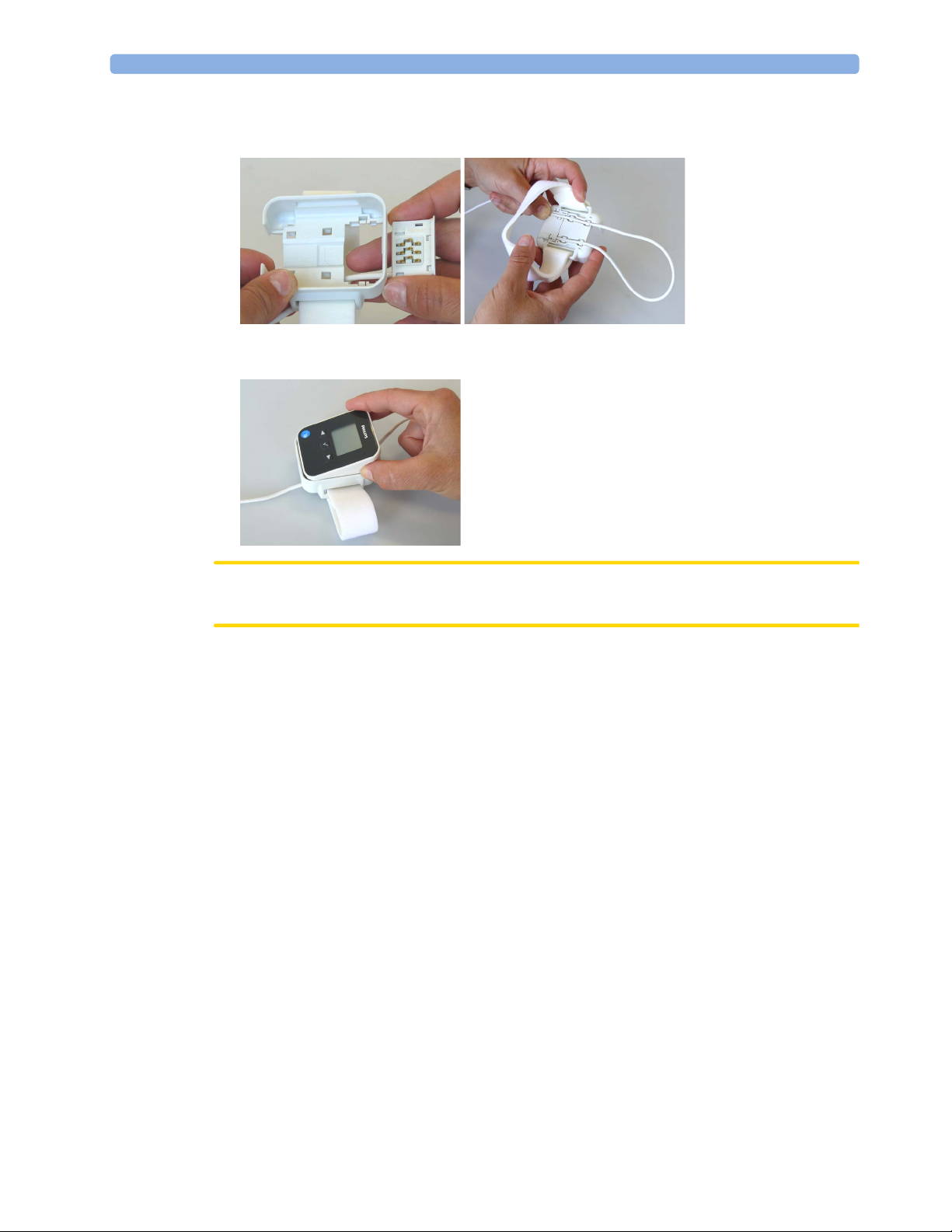
Connecting SpO2 Sensors
1 Connect the sensor to the single patient Mobile CL SpO2 Cradle (if not already connected).
2 IntelliVue CL SpO2 Pod
2 Insert the SpO
Pod into the Mobile CL SpO2 Cradle. The correct orientation is indicated by a
2
matching blue dot inside the cradle.
CAUTION
Make sure that the contacts of the SpO
Pod and the sensor are dry and free of residues.
2
3 Secure the cradle on the patient's arm using the wristband.
a. Feed the free end of the wristband through the slot in the cradle, starting from the underside of the
cradle.
b. Slide the wristband onto the patient's arm and pull the free end until the wristband fits snugly.
c. Close the wristband using the Velcro patch on the free end of the band.
29
Page 30

2 IntelliVue CL SpO2 Pod
Removing the Pod from the Cradle
To remove the SpO2 Pod from the cradle, pull on the Pod at the opening in the cradle, while holding the
cradle in place on the patient's arm.
Applying the Sensor
1 Choose a finger of the patient that matches the sensor dimension in a way that the sensor optical
components are properly aligned and the sensor is neither too loose nor applies too much pressure to
the finger. For small pediatric patients consider the thumb.
2 Remove colored nail polish from the application site.
3 Apply the sensor to the patient. The application site should match the sensor size so that the sensor can
neither fall off, nor apply excessive pressure. See the sections below for details on applying the different
sensors.
4 Check that the light emitter and the photodetector are directly opposite each other. All light from the
emitter must pass through the patient's tissue.
30
WARNING
Proper Sensor Fit: If a sensor is too loose, it might compromise the optical alignment or fall off. If it is too
tight, for example because the application site is too large or becomes too large due to edema, excessive
pressure may be applied. This can result in venous congestion distal from the application site, leading to
interstitial edema, hypoxemia and tissue malnutrition. Skin irritations or lacerations may occur as a result of
the sensor being attached to one location for too long. To avoid skin irritations and lacerations, periodically
inspect the sensor application site and change the application site regularly.
Venous Pulsation: Do not apply sensor too tightly as this results in venous pulsation which may severely
obstruct circulation and lead to inaccurate measurements.
Ambient Temperature: At elevated ambient temperatures be careful with measurement sites that are not
well perfused, because this can cause severe burns after prolonged application. All listed sensors operate
without risk of exceeding 41°C on the skin if the initial skin temperature does not exceed 35°C.
Extremities to Avoid: Avoid placing the sensor on extremities with an arterial catheter, an NBP cuff or an
intravascular venous infusion line.
Page 31

Measuring SpO2
During measurement, ensure that the application site:
– has a pulsatile flow, ideally with a perfusion indicator value above 1.0 or, if the perfusion indicator is
– has not changed in its thickness (for example, due to edema), causing an improper fit of the sensor.
WARNING
2 IntelliVue CL SpO2 Pod
not available, with signal quality indicator of at least medium.
• If not specified otherwise in the SpO
sensor's instructions for use, the following applies:
2
– For fully conscious pediatric or adult patients, who have a normal function of perfusion and
sensory perception at the measurement site:
To ensure skin quality and correct optical alignment of the sensor, inspect the application site when
the measurement results are suspicious or when the patient complains about pressure at the
application site, but at least every 24 hours. Correct the sensor alignment if necessary. Move the
sensor to another site, if the skin quality changes.
– For all other patients:
Inspect the application site every two to three hours to ensure skin quality and correct optical
alignment. Correct the sensor alignment if necessary. If the skin quality changes, move the sensor
to another site.
Change the application site at least every four hours.
• Injected dyes such as methylene blue, or intravascular dyshemoglobins such as methemoglobin and
carboxyhemoglobin may lead to inaccurate measurements.
• Inaccurate measurements may result when the application site for the sensor is deeply pigmented or
deeply colored, for example, with nail polish, artificial nails, dye or pigmented cream.
• Interference can be caused by:
– High levels of ambient light (including IR warmers) or strobe lights or flashing lights (such as fire
alarm lamps). (Hint: cover application site with opaque material.)
– Another SpO
sensor in close proximity (e.g. when more than one SpO2 measurement is
2
performed on the same patient). Always cover both sensors with opaque material to reduce crossinterference.
– Electromagnetic interference, especially at perfusion indicator values below 1.0 or signal quality
indicator below medium.
– Excessive patient movement and vibration.
Selecting Measurement Modes
There are three different modes available for making SpO2 measurements:
• Continuous mode - SpO
• Manual mode - a single SpO
menu item is selected. One set of values is then displayed with the time the measurement was made.
• Automatic mode - a series of measurements is made with an interval between them. The interval is
selected using the
automatically when automatic mode is selected.
The values measured in manual mode or automatic mode will be displayed for a configurable time span.
After that the values are regarded as invalid and are no longer displayed. Battery power usage will be
appreciably higher when measuring in continuous mode, in comparison to manual or automatic mode,
resulting in a reduced battery runtime.
Repeat Time SmartKey or the Repeat menu item. The measurement starts
is measured continuously until the measurement is switched off.
2
measurement is made when the Start SpO₂ SmartKey or the Start SpO₂
2
31
Page 32

2 IntelliVue CL SpO2 Pod
Starting and Stopping Measurements
Use the setup menu or SmartKeys to start measurements manually:
Action to be Performed SpO
Start manual measurement
When manual measurements are made, there will be no continuous SpO
manual measurement value reflects a momentary status. The numerics from SpO
manual mode will remain for a time on the main screen. They are annotated with the time that the
measurement was made to distinguish them from continuously measured values.
Understanding SpO2 Numerics and Symbols
1 SpO2 numeric
2 Pulse rate numeric
3 Symbol indicating pulse rate
4 Measurement mode - indicates here that Auto mode is
active and shows the time to the next measurement.
5 Alarms Off symbol for Pulse
6 Timestamp
7 Alarms Off symbol for SpO
menu SmartKeys
2
Start SpO₂
monitoring or alarming. The
2
2
Start
measurements made in
2
Note: The Alarms Off symbols indicate that no physiological alarms are available from the Cableless
Measurement Devices when not assigned to a host.
SpO2 Signal Quality Indicator
The SpO2 numeric is displayed together with a signal quality indicator (if configured and enough space is
available) which gives an indication of the reliability of the displayed values.
The level to which the triangle is filled shows the quality of the signal; the indicator below shows a medium
signal quality, the signal quality is at a maximum when the triangle is completely filled.
1 SpO2 Quality Indicator
32
Page 33

Assessing a Suspicious SpO2 Reading
Traditionally, pulse rate from SpO2 was compared with heart rate from ECG to confirm the validity of the
SpO
reading. With newer algorithms, such as FAST-SpO2, this is no longer a valid criteria because the
2
correct calculation of SpO
is not directly linked to the correct detection of each pulse.
2
When pulse rate is very low, or strong arrhythmia is present, the SpO
rate calculated from ECG but this does not indicate an inaccurate SpO
If you doubt the measured SpO
, use the signal quality indicator (if available) or, when used with a patient
2
monitor, the pleth wave and perfusion indicator on the monitor to assess the signal quality.
WARNING
With pulse oximetry, sensor movement, ambient light (especially strobe lights or flashing lights) or
electromagnetic interference can give unexpected intermittent readings when the sensor is not attached.
Especially bandage-type sensor designs are sensitive to minimal sensor movement that might occur when
the sensor is dangling.
Changing the Averaging Time
Depending on the monitor configuration, you may be able to change the averaging time for the SpO2
values.
The averaging time represents the approximate time period used for the calculation. The exact averaging
time also depends on the signal conditions. The longer the averaging time, the longer the time needed until
the SpO
pulse rate and perfusion (only available at the patient monitor). Fast averaging is useful for situations where
an extremely fast measurement is required or few artifacts are expected. Use slow averaging where you
expect the number of artifacts to be relatively high.
1 In the
2 Select the required averaging time from the list.
values reflect the physiological event. The same averaging is applied to all numerical values: SpO2,
2
SpO₂ menu, select Average.
2 IntelliVue CL SpO2 Pod
pulse rate may differ from the heart
2
value.
2
Perfusion Numeric (only available on the Patient Monitor)
The perfusion numeric (Perf) gives a value for the pulsatile portion of the measured signal caused by the
pulsating arterial blood flow.
You can also use the perfusion numeric as a quality indicator for the SpO
optimal, between 0.3-1 is acceptable. Below 0.3 is marginal; reposition the sensor or find a better site.
measurement. Above 1 is
2
33
Page 34

2 IntelliVue CL SpO2 Pod
Alarms
The IntelliVue Cableless Measurements have two different types of alarm: patient alarms and technical
alarms (INOPs).
Patient Alarms
Patient Alarms are high priority alarms (such as a potentially life threatening situation), also called red
alarms, or medium priority alarms, also called yellow alarms.
Technical Alarms (INOPs)
Technical alarms, also known as INOPs, indicate that the measuring device cannot measure reliably. If an
INOP interrupts monitoring, there will be a question mark in place of the measurement numeric. An INOP
tone sounds at the Cableless Measurement Device only when there is no SRR connection to a host.
Exception: the Battery empty INOP tone sounds also with SRR connection.
Most INOPs are low priority, however there are a small number of INOPs which, due to their severity, are
medium or high priority.
Alarm Delays
There is a delay between a physiological event at the measurement site and the corresponding alarm
indication at the Cableless Measurement Device. This delay has two components:
• The general measurement delay time is the time between the occurrence of the physiological event and
when this event is represented by the displayed numerical values. This delay depends on the algorithmic
processing.
• The time between the displayed numerical values crossing an alarm limit and the alarm indication on
the device is the system alarm delay. The system alarm delay is the processing time the system needs for
any alarm on the Cableless Measurement Device to be indicated after the measurement has triggered
the alarm. This delay depends on the Cableless Measurement Device and the connected host system.
See the performance specifications in the chapter “IntelliVue CL SpO2 Pod Specifications” on
page 133 for the system alarm delay specification of the Cableless Measurement Device.
The alarm delay configured for a specific measurement is normally a fixed time.
Multiple Alarms
If more than one alarm is active, the alarm messages are shown in the alarm status area in succession. An
arrow symbol next to the alarm message informs you that more than one message is active.
The Cableless Measurement Device sounds an audible indicator for the highest priority alarm. If more than
one alarm condition is active in the same measurement, the Cableless Measurement Device announces the
most severe.
NOTE
If you want to use local attended monitoring, make sure to have all Cableless Measurement Devices
upgraded to at least Rev. B.02.
Visual Alarm Indicators
WARNING
• No patient alarms are available on the Cableless Measurement Devices when assigned to a host monitor
(unless they are selected for use in patient transport at the monitor they are assigned to) or
GuardianSoftware.
• Visual patient alarm indicators are disabled on the Cableless Measurement Devices when connected to
a host monitor (unless they are selected for use in patient transport at the monitor they are assigned to)
or GuardianSoftware.
34
Page 35

Alarm Message
Alarm messages are displayed in black on a light gray background in the alarm status area at the top of the
screen indicating the source of the alarm and coded according to their severity. If more than one
measurement is in an alarm condition, the message changes every few seconds, and has an arrow ( ) at the
side. The asterisk symbols (
yellow alarms. Standard INOPs do not have a symbol, red and yellow INOPs have exclamation marks
beside the alarm message:
An alarm message that appears is automatically highlighted. Use the key to silence the message. A
message is displayed at the bottom of the screen and highlighted. Press again to confirm the
acknowledgment of the alarm. After the confirmation, any ongoing alarm message is displayed in the icon
tray of the screen.
Alarm States
Depending on the alarm state of your Cableless Measurement Device, the following icons may be displayed
on the device:
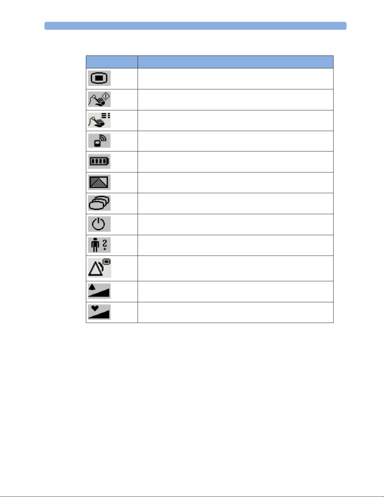
Icon Description
2 IntelliVue CL SpO2 Pod
*) beside the alarm message match the alarm priority: *** for red alarms, ** for
!!! for red INOPs and !! for yellow INOPs.
Silence
No local alarming on Cableless Measurement Device. The device is connected
to a host monitor or telemetry device and has no visual or audible patient alarm
indicators. The device will only display INOP messages.
Audible Alarm Indicators
Audible alarm indicator patterns are repeated until you acknowledge the alarm by switching it off or pausing
it, or until the alarm condition ceases (if audible alarm indication is set to non-latching).
Cableless Measurements Devices alone (without host, e.g. a patient monitor) are not suitable for unattended
monitoring due to their limited alarm volume.
WARNING
• Do not rely exclusively on the audible alarm system for patient monitoring. Adjustment of alarm
volume to a low level or off during patient monitoring may result in patient danger. Remember that the
most reliable method of patient monitoring combines close personal surveillance with correct
operation of monitoring equipment.
• No patient alarms are available on the Cableless Measurement Devices when connected to a host
monitor (unless they are selected for use in patient transport at the monitor they are assigned to) or to
GuardianSoftware.
• When connected to a host monitor or GuardianSoftware, no alarm tones are available on the Cableless
Measurement Devices (unless they are selected for use in patient transport at the monitor they are
assigned to).
Alarms are switched off.
Alarm volume is set to 0.
35
Page 36

2 IntelliVue CL SpO2 Pod
Silencing an Alarm
To silence an alarm, select the alarm message and press the key.
This will silence the alarm tone and clear the alarm message. If the condition which caused the alarm is still
present, the alarm indicator will be displayed in the icon tray of the screen.
When using a Cableless Measurement Pod with an IntelliVue Information Center iX Release A, make sure
to remove the pod at the telemetry device and only when in SRR range of the telemetry device. Otherwise
you will get a technical alarm (
cl SpO₂ Disconnect) that can not be silenced at the telemetry device. You will
then have to reboot the telemetry device to remove the message.
Displaying a List of Current Alarms
To display a list of the currently active alarms,
1 Select the
2 Select
Alarms SmartKey or Main Setup SmartKey, followed by Alarms.
Alarm Messages.
1 Full length alarm message
2 Alarm indicator
Setting the Volume of the Alarm Tone
To set the volume for the Alarm tone,
1 Select the
2 Select
Alarms SmartKey or Main Setup SmartKey, followed by Alarms.
AlarmVol and select a volume setting. The maximum is 10 and the minimum depends on your
configuration.
If the volume of the Alarm tone is set to zero, the following symbol is displayed on the right icon tray of the
Cableless Measurement Device screen:
NOTE
No Alarm tone will sound at the device as long as it is within the SRR range.
Minimum Volume for No Host Monitoring INOP
If your device is connected to a host monitor, and the connection is interrupted, the INOP message No
Host Monitoring
INOP, and any other active alarm, is not overlooked, the INOP and alarm tones may be configured to have
a minimum volume. In this case, INOP and alarm tones will sound even if the device alarm volume is set to
zero.
will appear within 30 seconds, accompanied by an INOP tone. To help ensure that this
36
Page 37

Alarm Reminder
If Reminder is configured on your device, you will get an audible reminder of alarm conditions that remain
active after you have silenced the alarm. This reminder may take the form of a repetition of the alarm tone
for a limited time, or an unlimited repetition of the alarm tone (this is the same as a new alarm). Alarm
Reminder is not available for standard, light blue INOPs but for yellow and red INOPs.
In Configuration Mode, you can set the interval between silencing the alarm and sounding the reminder
tone to one, two, or three minutes.
Pausing or Switching Off Alarms
If you want to temporarily prevent alarms from sounding, for example while you are moving a patient, you
can pause alarms. Depending on your device configuration, alarms are paused for one, two, or three
minutes, or infinitely. Infinite alarm pause is equivalent to switching the alarms off.
To view the alarm pause setting chosen for your unit,
1 In the SmartKeys Menu select
2 Check the setting.
This setting can only be changed in Configuration Mode.
To Pause or Switch Off Alarms
2 IntelliVue CL SpO2 Pod
Main Setup, Alarms, then OffDurat.
Select the key in the SmartKeys Menu followed by Alarms. Press the hardkey to switch to
Paused. If your device is configured to infinite pause time, selecting this option switches alarms off.
Restarting Paused Alarms
To manually switch on alarm indication again after a pause, select the key again.
Alarm indication starts again automatically after the pause period expires. If the device is configured to stay
paused infinitely, you must select again to restart alarm indication.
37
Page 38

2 IntelliVue CL SpO2 Pod
Alarm Limits
The alarm limits you set determine the conditions that trigger yellow and red limit alarms. For SpO2, where
the value ranges from 100 to 0, setting the high alarm limit to 100 switches the high alarm off. In these
cases, the alarms off symbol is not displayed.
WARNING
Be aware that the devices in your care area may each have different alarm settings, to suit different patients.
Always check that the alarm settings are appropriate for your patient before you start monitoring.
Adjusting the Alarm Limits
1 Select the Alarms SmartKey followed by Alarm Limits (or select Main Setup followed by SpO₂):
2 Select
3 Select
WARNING
High oxygen levels may predispose a premature infant to retrolental fibroplasia. If this is a consideration do
NOT set the high alarm limit to 100%, which is equivalent to switching the high alarm off.
High Lim then choose the high alarm limit.
Low Lim then choose the low alarm limit.
Adjusting the Desat Limit Alarm
The Desat alarm is a high priority (red) alarm notifying you of potentially life threatening drops in oxygen
saturation.
1 In the
SpO₂ menu, select DesatLim.
2 Adjust the limit.
Setting Up Tone Modulation
Only when the Cableless Measurement Device is not connected to a host:
If tone modulation is on, the pulse tone pitch lowers when the SpO
Main Setup followed by User Interface. In this menu, select Tone Modulation to switch between Yes
Select
(for on) and
No (for off).
NOTE
If the SpO
level drops below 52%, two short tones will be issued rather than one long tone.
2
Latching Alarms
The alarm latching setting for your device defines how the alarm indicators behave when you do not
acknowledge them. When alarms are set to non-latching, their indicators end when the alarm condition
ends. Switching alarm latching on means that visual and/or audible alarm indications are still displayed or
announced by the device after the alarm condition ends. The indication lasts until you acknowledge the
alarm.
level drops.
2
38
Page 39

Viewing the Alarm Latching Settings
To see the alarm latching setting for your device,
1 In the
2 Here you can see the
Main Setup menu, select Alarms.
Visual Latching and Audible Latching settings.
This setting can only be changed in Configuration Mode. You should be aware of the settings chosen for
your unit. There are three possible choices each for visual and audible latching, red only, red and yellow, and
off. These choices can be combined to give the following settings:
Visual Latching Audible Latching
Red&Yellow Red&Yellow
Red&Yellow Red Only
Red&Yellow Off
Red Only Red Only
Red Only Off
Off Off
Alarm Latching Behavior
2 IntelliVue CL SpO2 Pod
Red & Yellow Measurement
Non-latching alarms Visual and audible latching Visual latching, audible
Alarms
Alarm has not
been
acknowledged.
Alarm has been
acknowledged.
Alarm condition
still present.
Alarm condition
no longer present.
Alarm condition
still present.
Alarm condition
no longer present.
Alarm tone on. Alarm message. Alarm tone on. Alarm
All audible and visual alarm
indicators automatically stop.
All audible and visual alarm
indicators automatically stop.
Audible and visual alarm
indicators automatically stop.
All INOPs are non-latching.
Testing Alarms
When you switch the CL SpO2 Pod on, a selftest is started. You must check that the backlight switches on,
and that you hear a single tone. This indicates that the alarm indicators are functioning correctly. For further
testing of individual measurement alarms, perform the measurement on yourself or use a simulator. Adjust
alarm limits and check that appropriate alarm behavior is observed.
Alarm Behavior at Power On
If the device is switched off (Standby), all alarm settings are maintained. If the device is switched off
completely (
settings will be lost unless they were actively saved by storing the active profile before the device was
switched off. See “Switching the Device Off” on page 17 and “Using Profiles” on page 18 for details.
When the device is switched back on from either state, it will start in Profile A and you may have to switch
to the desired profile which contains your alarm settings.
After any of these situations, you should check that the alarm settings are appropriate for your patient and
monitoring situation, and if necessary, select the correct profile and patient category.
Power Off), or the battery is completely empty, resulting in complete power loss, all alarm
message.
Alarm tone on.
Alarm message.
All audible and visual alarm
indicators automatically stop.
Audible and visual alarm
indicators automatically stop.
non-latching
Alarm tone on. Alarm
message.
Alarm message.
Audible alarm indicators
automatically stop.
All audible and visual alarm
indicators automatically stop.
Audible and visual alarm
indicators automatically stop.
39
Page 40

2 IntelliVue CL SpO2 Pod
Reference List of Patient Alarms
Alarm Message, Indication Source Condition
*** Brady (Pulse) SpO
2
The heart rate from the Pulse signal has fallen below the
bradycardia limit.
*** Desat SpO
2
The SpO2 value has fallen below the desaturation alarm
limit.
** Pulse High SpO
** Pulse Low SpO
** <SpO₂ Label> High SpO
2
2
2
The pulse rate has exceeded the high alarm limit.
The pulse rate has dropped below the low alarm limit.
The arterial oxygen saturation has exceeded the high alarm
limit.
** <SpO₂ Label> Low SpO
2
The arterial oxygen saturation has dropped below the low
alarm limit.
*** Tachy (Pulse) SpO
2
The Pulse Rate from the Pleth signal has exceeded the
tachycardia limit
Reference List of all INOPs
INOP Message, Indication Source What to do
Batt Incompatible
INOP tone
Batt Malfunction
INOP tone
Battery Empty
INOP tone
Battery Low
INOP tone
Check Batt Temp
INOP tone
Check Battery
INOP tone
Check Charger I/F
INOP tone
Battery Battery cannot be used with this Cableless Measurement
Device. Replace battery with one that has been approved for
use with this Cableless Measurement Device. Contact your
service personnel.
Battery Malfunction of the battery system detected (charger circuit
or battery). Contact your service personnel.
Battery The remaining monitoring time is below 30 minutes. Charge
battery.
Battery The remaining monitoring time is below 2 hours.
Battery The temperature of the battery is critically high. Check that
Cableless Measurement Device is not covered and not
exposed to a heat source. If INOP persists, remove
Cableless Measurement Device from patient and contact
your service personnel.
Battery The maximum number of charge/discharge cycles of the
battery will be reached in less than 50 cycles. Contact your
service personnel to replace the battery.
Battery Overvoltage or undervoltage detected at the charger
interface. Clean contacts of charger interface at Cableless
Measurement Device and charging station. If the INOP
persists, contact your service personnel.
40
Page 41

INOP Message, Indication Source What to do
2 IntelliVue CL SpO2 Pod
cl SpO₂ Chk Sett
INOP tone
cl SpO₂ Disconnect
only at the host
No Host Monitoring
INOP tone
No System Cableless Measurement
Cableless Measurement
Device
Cableless Measurement
Device
Cableless Measurement
Device
Device
Remove From Pat
INOP tone
Service Battery
Cableless Measurement
Device
Battery Maximum number of charge/discharge cycles for battery
INOP tone
<SpO₂ Label> Equip Malf
SpO
2
Numeric is replaced by -?INOP tone
<SpO₂ Label> Erratic
SpO
2
Numeric is replaced by -?INOP tone
<SpO₂ Label> Extd.Update
SpO
2
Numeric is replaced by -?-
<SpO₂ Label>Interference
SpO
2
Numeric is replaced by -?INOP tone
<SpO₂ Label> Low Perf
SpO
2
Numeric is replaced by -?-
<SpO₂ Label> NeoPatient?
SpO
2
Numeric is replaced by -?INOP tone
If this INOP appears and an INOP tone sounds, check the
Cableless Measurement Device and patient settings before
you resume making measurements. If the settings are
unexpected, there may be a problem with the Cableless
Measurement Device software. Contact your service
personnel.
If this INOP is acknowledged at the Cableless Measurement
Device, it is cleared. If it is silenced remotely, only the tone is
cleared.
The SpO
Pod has lost the SRR connection to the telemetry
2
device or the patient monitor.
There is a problem with the communication to the assigned
patient monitor or telemetry device and monitoring is
currently not possible (no patient alarms or information).
Check the connection. Contact your service personnel.
There is a problem with the communication to the assigned
IntelliVue GuardianSoftware and monitoring is currently
not possible (no patient alarms or information). Check the
connection. Contact your service personnel.
Displayed on the Cableless Measurement Device. The
temperature of the battery is too high. Remove the Cableless
Measurement Device from the patient and contact service
personnel.
exceeded. Charging of the battery is inhibited. Contact your
service personnel to replace battery.
The SpO2 Pod is faulty. Contact your service personnel.
Check the sensor placement. Try another adapter cable and
sensor. If the INOP persists, contact your service personnel.
The update time for displayed values is extended due to an
NBP measurement on the same limb or an excessively noisy
signal.
There is too much interference, caused by a high level of
ambient light and/or electrical interference. Cover the
sensor to minimize ambient light. If the INOP persists,
make sure that the sensor cable is not damaged or
positioned too close to power cables.
Accuracy may be compromised due to very low perfusion.
Stimulate circulation at sensor site. If INOP persists, change
the measurement site.
The patient monitor the SpO2 Pod is assigned to is in
neonatal mode. The INOP will remain active until the
monitor is changed to adult or pediatric mode.
41
Page 42

2 IntelliVue CL SpO2 Pod
INOP Message, Indication Source What to do
<SpO₂ Label> No Pulse
SpO
Numeric is replaced by -?INOP tone
<SpO₂ Label> No Sensor
SpO
Numeric is replaced by -?INOP tone
<SpO₂ Label> NoisySignal
SpO
Numeric is replaced by -?INOP tone
<SpO₂ Label> Poor Signal SpO
<SpO₂ Label> Pulse?
SpO
Numeric is replaced by -?INOP tone
<SpO₂ Label> Searching
SpO
Numeric is unavailable
<SpO₂ Label> Sensor Malf
SpO
Numeric is replaced by -?INOP tone
<SpO₂ Label> Sensor Off
SpO
Numeric is replaced by -?INOP tone
<SpO₂ Label> Unkn.Sensor
SpO
Numeric is replaced by -?INOP tone
<SpO₂ Label> Upgrade
SpO
Numeric is replaced by -?-
2
Check the perfusion at the measurement site. If necessary,
stimulate circulation or change the measurement site. If the
INOP is due to an NBP measurement on the same limb,
wait until the NBP measurement is finished.
2
Make sure the SpO2 sensor is connected. If the INOP
persists, try another sensor. If you acknowledge this INOP,
the measurement will be switched off.
2
Excessive patient movement or electrical interference is
causing irregular pulse patterns. Try to reduce patient
movement or to relieve the cable strain on the sensor.
2
The signal quality of the SpO2 measurement is poor. The
accuracy may be compromised.
2
The detectable pulsations of the SpO2 signal are outside the
specified pulse rate range.
2
The patient signal is analyzed, but no valid numerics are
available yet.
2
The SpO2 sensor is faulty. Try another sensor. If the INOP
persists, contact your service personnel.
2
The algorithm has determined that a sensor is connected,
but not properly applied to the patient. The ability of the
algorithm to detect this condition depends on the used
sensor type.
2
The connected SpO2 sensor is not supported by this
measurement hardware.
2
SpO2 in upgrade mode, no patient monitoring possible.
42
Page 43

Local Attended Monitoring
When working with an IntelliVue MP5, MP5SC, MP5T Patient Monitor with software revision J.2 or higher
as a host, or with an IntelliVue X2 Multi-Measurement Module with software revision K.2 or higher, the
IntelliVue CL SpO
you want to have alarm indications at the CL Pods when they are out of reach of the patient monitor
(disconnected). The patient monitor setting to switch CL Measurement Alarms on and off (
) is used to enable and disable this functionality. As a default, the CL Measurement Alarms are on.
Off
Local Attended Monitoring Enabled
By default, the patient monitor is set to receive alarms from the CL Pods (can only be changed in
configuration mode). This scenario is used for patients who require uninterrupted monitoring. The various
alarms from the CL Pods are indicated at the patient monitor if they are enabled at the monitor. When the
CL Pod is disconnected from the patient monitor and the caregiver has activated the transport mode at the
monitor, physiological alarms are indicated locally at the CL Pod. A
the monitor if the SRR connection is lost and the transport mode has not been activated.
CL Pod connected to a patient monitor and CL Measurement Alarms On (Standard Use Model):
and NBP Pods can be used for local attended monitoring. This is for situations where
2
2 IntelliVue CL SpO2 Pod
cl Alarms On/
cl SpO₂ Disconnect INOP is shown at
SRR connection
At the CL Pod:
Indication of technical
alarms only
At the monitor:
Indication of physiological and
technical alarms from CL Pods
CL Pod disconnected from patient monitor and CL Measurement Alarms On, Local Attended
Monitoring:
No SRR connection
At the CL Pod:
Indication of technical and
physiological alarms
At the monitor:
No indication of physiological
alarms from CL Pods. No
indication of technical alarms
after disconnection.
43
Page 44

2 IntelliVue CL SpO2 Pod
Local Attended Monitoring Disabled
The patient monitor is set to cl Alarms Off (this can only be done in configuration mode). This scenario is
used if the patients do not require permanent monitoring and are mobile, but vital signs are taken from time
to time. All alarms from the CL Pods are switched off at the monitor. If the SRR connection is lost, no
SpO₂ Disconnect
CL Pod connected to a patient monitor and CL Measurement Alarms Off:
INOP is shown at the monitor in this scenario.
cl
SRR connection
At the CL Pod:
Indication of technical
alarms only
At the monitor:
No indication of physiological
alarms from CL Pods.
Indication of technical alarms
from CL Pods.
CL Pod disconnected from patient monitor and CL Measurement Alarms Off:
No SRR connection
At the CL Pod:
Indication of technical
alarms only
At the monitor:
No indication of physiological
and technical alarms from CL
Pods.
44
Page 45

2 IntelliVue CL SpO2 Pod
Alarm Availability: Standard Use Model versus Local Attended Monitoring with CL Measurement Alarms On
12
Standard Use Model Local Attended Monitoring
->
Caregiver activates
'Use for transport'
<Caregiver activates
'Use with monitor'
SRR connection
Action / Event Situation Alarm Availability
at CL Pod
no SRR connection
Alarm Availability
at Patient Monitor
Standard Use Model:
normal operation,
no special action
CL Pod connected to the
patient monitor (1)
Technical alarms
(own)
No physiological alarms
No Local Alarming icon is
displayed:
Technical alarms
(own + from Pod)
Physiological alarms
(own + from Pod)
45
Page 46

2 IntelliVue CL SpO2 Pod
Activation of Local Attended
Monitoring:
Caregiver activates Local
Attended Monitoring and
Patient is in transport without
connection to the host system,
caregiver attends the patient
(2)
Technical alarms
(own)
Physiological alarms
(own)
disconnects CL Pod temporarily
by setting
Patient Monitor's
Use for Transp. in the
Equipment
window
Deactivation of Local
Attended Monitoring:
Caregiver deactivates Local
Attended Monitoring and
reconnects CL Pod to a patient
monitor by setting
in the patient monitor's
Monitor
Equipment window
Use with
Patient returns from
transport.
Back to the standard use
model (1)
Technical alarms
(own)
No physiological alarms
No Local Alarming icon is
displayed:
Special Case:
Connection lost while in Standard Use Model
Action / Event Situation Alarm Availability
at CL Pod
Technical alarms
(own)
Physiological alarms
(own)
No alarms from CL Pod
Technical alarms
(own + from Pod)
Physiological alarms
(own + from Pod)
Alarm Availability
at Patient Monitor
Alternative Use Model:
CL Pod temporarily
disconnected from a monitor
due to unintentional loss of
connection (e.g. out of range),
Local Attended Monitoring
has not been activated by the
caregiver
No Host Monitoring INOP
at CL Pod
cl SpO₂ Disconnect INOP
at patient monitor
Local Attended
Monitoring is
automatically activated (2)
Technical alarms
(own)
Physiological alarms
(own)
Technical alarms
(own)
Physiological alarms
(own)
No alarms from CL Pod
46
Page 47

2 IntelliVue CL SpO2 Pod
Alarm Availability: Standard Use Model versus Local Attended Monitoring with CL Measurement Alarms Off
34
Patient within Range Patient Mobile
->
Patient mobile
<-
Patient back
SRR connection
Action / Event Situation Alarm Availability
at CL Pod
no SRR connection
Alarm Availability
at Patient Monitor
Connected, but no CL Alarms
(CL Measurement Alarms
Off):
normal operation,
no special action
CL Pod connected to the
patient monitor (3)
Technical alarms
(own)
No physiological alarms
No Local Alarming icon is
displayed:
Technical alarms
(own + from Pod)
Physiological alarms
(own)
47
Page 48

2 IntelliVue CL SpO2 Pod
Patient is leaving the vicinity
of the monitor:
no special action
Patient returns to the vicinity
of the monitor:
no special action
Patient is mobile without
connection to the host system
(4)
Patient returns.
Back to connected status (3)
Technical alarms
(own)
No physiological alarms
Alarms Off icon is displayed
in front of each numeric:
Technical alarms
(own)
No physiological alarms
No Local Alarming icon is
displayed:
Technical alarms
(own)
Physiological alarms
(own)
No alarms from CL Pod
Technical alarms
(own + from Pod)
Physiological alarms
(own + from Pod)
48
Page 49

2 IntelliVue CL SpO2 Pod
SpO2 Default Settings
These are the most important default settings of your IntelliVue CL SpO2 Pod as they are delivered from
the factory. For a comprehensive list and explanation of default settings, see the Configuration Guide
supplied with your devices. The default settings can be permanently changed in Configuration Mode. When
the Pod is assigned to a patient monitor, the settings defined at the patient monitor will overwrite the
settings defined at the Pod.
SpO2 Settings Factory Defaults
Adult Pedi Neo
Mode Continuous Continuous Continuous
Repeat Time 15 min 15 min 15 min
Alarms On On On
Pulse Volume 111
ToneMod. Yes Yes Yes
Perfusion OnOnOn
Average 10 sec 10 sec 10 sec
NBP Alarm Suppr. OnOnOn
Aging Time 10 min 10 min 10 min
Color Cyan
Average in Mon. No No No
Signal Quality OnOnOn
Label SpO₂ SpO₂ SpO₂
(light blue) Cyan (light blue) Cyan (light blue)
SpO2 Alarm Default Settings
Setting Adult Pedi Neo
DesatLim 80 80 80
Low Lim 90 90 85
High Lim 100 100 95
Desat Delay 20 sec 20 sec 20 sec
High Alarm Delay 10 sec 10 sec 10 sec
Low Alarm Delay 10 sec 10 sec 10 sec
Pulse Settings Factory Defaults
Adult Pedi Neo
Pulse OnOnOn
Alarms On On On
High Lim 120 160 200
Low Lim 50 75 100
Δ Brady 202020
Brady Clamp 40 40 50
49
Page 50

2 IntelliVue CL SpO2 Pod
Pulse Settings Factory Defaults
Adult Pedi Neo
Δ Tachy 202020
Tachy Clamp 200 220 240
Integrated Battery Handling
Only qualified and authorized service personnel (biomedical engineers or technicians) should change
batteries.
Battery Care
Battery care begins when you receive a new IntelliVue Cableless Measurement Device with built-in battery
and continues throughout the life of the device. The table below lists battery care activities and when they
should be performed.
Activity When to perform
Perform a visual inspection Before using the IntelliVue Cableless Measurement Device
Charge the battery Upon receipt, after use, or if a low battery state is indicated. To
optimize performance, a fully (or almost fully) discharged
battery should be charged as soon as possible.
Store the device in a state of charge in the
range of 40-50% and power off the device
completely.
When not in use for an extended period of time, or when the
device is shipped.
Handling Precautions
Lithium ion batteries store a large amount of energy in a small package. Use caution when handling the
IntelliVue Cableless Measurement Devices with built-in battery; misuse or abuse could cause bodily injury
and/or property damage.
• Handle with care.
• Do not expose the device to liquids.
• Do not attempt to disassemble the device.
• Do not put device in autoclave.
• Damaged devices should not be used anymore.
WARNING
• Do not crush or puncture - mechanical abuse can lead to internal damage and internal short circuits
which may not be visible externally.
• Do not incinerate the devices or expose them to temperatures above 60°C (140°F).
50
Page 51

Storage
If unused IntelliVue Cableless Measurement Devices are stored for an extended period of time:
• they should be powered off for storage
• they should be stored in a cool place, ideally between 15°C and 25°C (60°F and 77°F)
• the state of charge should be between 40 and 50%
• they should be recharged every six months
Storing in a cool place slows the aging process of the batteries. They should be fully charged prior to use.
Do not store the device at a temperature outside the range of -20°C (-4°F) to 60°C(140°F).
Do not store cableless devices in direct sunlight.
NOTE
Storing the devices at temperatures above 40°C (104°F) for extended periods of time could significantly
reduce the battery's life expectancy.
Battery Lifetime Management
The lifetime of a Lithium Ion battery depends on the frequency and duration of use. When properly cared
for, the useful life is approximately 4 years or 400 complete charge-discharge cycles, whichever comes first.
In addition, experience indicates that the incidence of failure may increase with battery service life due to the
accumulated stresses of daily use. We therefore strongly recommend that lithium ion batteries be replaced
after 4 years or 400 complete charge-discharge cycles.
To see the date of manufacture and the number of charge-discharge cycles:
1 Select the
2 Press the hardkey to view the battery details.
The date of manufacture and the number of charge-discharge cycles are listed with other battery data on the
screen. Use the ◄ hardkey to scroll through the list.
The age of a lithium ion battery begins at the date of manufacture.
Battery Smartkey or Main Setup followed by Battery.
2 IntelliVue CL SpO2 Pod
51
Page 52

2 IntelliVue CL SpO2 Pod
Accessories
You can order parts and accessories from Philips supplies at www.medical.philips.com or consult your local
Philips representative for details. Also consult the accessories' Instructions for Use, if available.
WARNING
Reuse: Never reuse single-patient sensors, accessories and so forth that are intended for single use, or
single patient use only. Reuse may compromise device functionality and system performance and cause a
potential hazard, in particular with regard to cross-contamination.
Philips’ approval: Use only Philips-approved accessories. Using non-Philips-approved accessories may
compromise device functionality and system performance and cause a potential hazard.
Accessories Compliant with EMC Standards
All accessories listed in the accessories sections comply, in combination with the IntelliVue Cableless
Measurements, with the requirements of IEC 60601-1-2.
IntelliVue CL SpO2 Pod Accessories
All listed sensors operate without risk of exceeding 41°C on the skin, if the initial skin temperature does not
exceed 35°C.
Make sure that you use only the accessories that are specified for use with this device, otherwise patient
injury can result.
Part Number Description Contents
989803165941 Mobile CL 20 single patient SpO
Cradles for use on pediatric and adult patients
>10 kg
Sensors and
2
20 Single-Patient Mobile CL DSpO2-1A Sensors
20 Single-Patient Wristbands
20 Single-Patient Cradles
pre-assembled
989803165921 Mobile CL 20 single patient SpO
Sensors for
2
20 Single-Patient Mobile CL DSpO2-1A Sensors
use on pediatric and adult patients >10 kg
989803165931
1
Mobile CL reusable SpO2 Sensor and Cradles
for use on pediatric and adult patients > 15 kg
1 Reusable Mobile CL RSpO2-1A Sensor
20 Single-Patient Cradles with pre-attached
Wristbands
989803165951 Mobile CL 20 SpO
Cradles (single patient) 20 Single-Patient Cradles with pre-attached
2
Wristbands
989803165961 Mobile CL 50 SpO
Wristbands (single
2
50 Single-Patient Wristbands
patient)
989803168861 Mobile CL SpO
Battery Kit 1 Battery
2
1 disassembly tool
1 front housing
1
May not be available in all geographies
52
Page 53

Maintenance and Troubleshooting
WARNING
Schedule: Failure on the part of the responsible individual hospital or institution employing the use of this
equipment to implement a satisfactory maintenance schedule may cause undue equipment failure and
possible health hazards.
Contact: If you discover a problem with any of the equipment, contact your service personnel, Philips, or
your authorized supplier.
Inspecting the Equipment and Accessories
You should perform a visual inspection before every use, and in accordance with your hospital's policy.
With the device switched off:
1 Examine unit exteriors for cleanliness and general physical condition. Make sure that the housings are
not cracked or broken, that everything is present, that there are no spilled liquids and that there are no
signs of abuse.
2 Inspect all accessories (cables, sensors and so forth). If any show signs of damage, do not use them.
WARNING
2 IntelliVue CL SpO2 Pod
If the IntelliVue Cableless Measurement Device is mechanically damaged, or if it is not working properly,
do not use it for any monitoring procedure on a patient, contact your service personnel.
Maintenance Task and Test Schedule
All maintenance tasks and performance tests are documented in detail in the service documentation
supplied on the IntelliVue Cableless Measurements documentation DVD. These tasks are for Philipsqualified service professionals only.
Ensure that these tasks are carried out as indicated by the device's maintenance schedule, or as specified by
local laws. Contact a Philips-qualified service provider if your device needs a safety or performance test.
Clean and disinfect equipment to decontaminate it before testing or maintaining it.
Troubleshooting
If a device will not switch on when you press a key, place it onto a charger slot on the charging station.
If you suspect a problem with an individual measurement device, read the Instructions for Use and
double check that you have set up the measurement correctly. Check also that the measurement has not
been switched off at the patient monitor that the device is assigned to.
If you suspect an intermittent, system-wide problem call your service personnel.
53
Page 54

2 IntelliVue CL SpO2 Pod
54
Page 55

3IntelliVue CL NBP Pod
To measure NBP, you need Philips standard cuffs, a Mobile CL NBP Cradle and a pouch and extension air
hose, or a Mobile CL NBP Cradle and Mobile CL Cuffs. When using Mobile CL Cuffs, the cradle is used to
attach the Pod to the cuffs and to allow easy removal of the Pod.
3
Standard Philips cuffs and specialized single-patient and reusable NBP cuffs are available for use with the
IntelliVue CL NBP Pod. For details regarding the cuffs and single-patient cradle, refer to “IntelliVue CL
NBP Pod Accessories” on page 94.
General Operation of the NBP Pod
The following sections describe operation on the NBP Pod itself. For operation from a patient monitor, see
“Controls Available with a Patient Monitor” on page 67. For operation from an Information Center via a
telemetry system, see “Controls Available with a Telemetry Device” on page 68. For operation with
IntelliVue GuardianSoftware, see “Controls Available with GuardianSoftware” on page 68.
The NBP Pods have three hardkeys for basic operation and a set of configurable SmartKeys which appear
on the screen. These are used to activate and navigate through the on-screen menus and to select individual
items. The typical operator's position is such that everything on the device's display can be read clearly and
easily.
Switching the Devices On
The first time an NBP Pod is used, or after the device has been powered off for storage, place it on the
IntelliVue CL Charging Station. This will automatically switch the device on.
If the NBP Pod has only been switched off temporarily (see “Switching the Device Off” on page 17), press
any hardkey to turn the device on again.
When an NBP Pod is not operated, it will automatically switch off the screen lighting after a short time. A
little later the low-activity screen will be displayed.
55
Page 56

3 IntelliVue CL NBP Pod
Screen Layout
There are three variations of the Main Screen layout depending on the Alarm status and the general activity
level.
Standard Layout
When assigned to a monitor, telemetry device or a patient in GuardianSoftware:
1 Connection status indicator
2 Indicator that alarming capability has been transferred to
the host (to the monitor or, for the telemetry device, to
the Information Center). No patient alarms will be
announced on the Cableless Measurement Device.
3 Battery indicator
4 Measurement values
5 Measurement-related symbols (see the “Monitoring
NBP” section for details)
6 Patient identification
Alarm Layout
When not assigned to a monitor or telemetry device:
1 Connection status indicator
2 Battery indicator
3 Measurement values
4 Measurement-related symbols (see the “Monitoring
NBP” section for details). The Alarms Off symbols
indicate that no physiological alarms are available from
the Cableless Measurement Devices when not assigned
to a host.
5 Cableless Measurement Device equipment label
If an alarm occurs the full alarm message appears at the top of the screen. After the alarm message has been
silenced the alarm indicator is shown as a symbol on the right side of the screen.
1 Full length alarm message
2 Alarm indicator
56
Page 57

Low-Activity Screen
If the Cableless Measurement Device has not been operated for a while, the screen lighting will switch itself
off and a little later the screen will switch to a pre-configured "low-activity" screen.
When a Cableless Measurement Device Cannot be Activated
If you cannot activate a device by pressing a key, place it on the IntelliVue CL Charging Station. The device
becomes active. Check the battery status. If necessary, leave the device on the charger until the battery is
fully charged.
Using the Hardkeys
The IntelliVue Cableless Measurement Devices have three hardkeys: ◄, , ►.
Use ◄ and ► to navigate through SmartKeys and menus and to select items or to silence alarms.
The three hardkeys also have an additional function when the key is held down for a couple of seconds:
◄ opens the Add To screen to assign a device (or to unassign it when it is already assigned)
3 IntelliVue CL NBP Pod
opens the SmartKeys menu
► returns to the Main Screen. If already on the Main Screen, it locks the keys and a lock symbol
appears on the screen above the battery symbol. If keys are already locked, it unlocks the keys and
the lock symbol disappears
Using the SmartKeys
A SmartKey is a graphical key which appears on the screen and gives you fast access to functions.
SmartKeys Menu
Press the hardkey (without any screen element highlighted) to get to the SmartKeys menu.
Use the ◄ and ► hardkeys to move along the row of SmartKeys. The highlighted SmartKey is displayed in
full above the row of SmartKeys. When you use the ◄ or ► hardkey at the end of the row, an
appears and then with further presses you move on to the next page of SmartKeys. To leave the SmartKeys
menu you can use the
Screen.
When the required SmartKey is highlighted, press the key to activate the corresponding function.
To get to the next page of the SmartKeys menu, highlight the rightmost SmartKey then press the ► key.
Exit screen
Exit screen or press the ► hardkey for a couple of seconds to return to the Main
57
Page 58

3 IntelliVue CL NBP Pod
List of Available SmartKeys
SmartKey Text Labels
Main Setup
- start/stop manual NBP measurement
- start auto series
- start measurement sequence
- stop current automatic measurement within series
stop any NBP measurement and measurement series
start NBP STAT measurement
start venipuncture (inflate cuff to subdiastolic pressure)
set the NBP repetition time
Add/Remove device
Battery menu
enter
change Screen
Profiles menu
enter
put the device in standby mode (or power off when pressed for more than two
seconds)
Patient menu
enter
enters the
Alarms menu to access: Alarm Messages, Alarm Limits, Alarms On/
Off/Pause, Alarm Volume.
change alarm volume
change pulse tone volume
58
access NBP mode selection and setup, with direct start/stop function
Page 59

Using the Main Setup Menu
In addition to the hardkeys and SmartKeys for the most needed functions, the Main Setup menu gets you to
all settings that can be adjusted for the respective device. Select the
menu.
Setup
Main Setup
NBP
Alarms
Patient
Equipment
User Interface
Standby
Profiles
Operating Modes
Date, Time
Battery
Revisions
3 IntelliVue CL NBP Pod
Main Setup SmartKey to get to the Main
Switching the Device Off
To put the device in standby mode, select the Standby SmartKey, then Confirm.
If you keep
•
Standby pressed for more than two seconds, you can choose between Standby or Power Off.
Standby means that the display is switched off and the measurements are disabled. Use this option if
your device is not used temporarily. Press any hardkey to turn the device on again.
•
Power Off means that the device is switched off completely and can only be switched on again by
putting it on a charger. Use this option when the device is not used for a longer time or prepared for
storage or shipping.
Auto Standby and Auto Power Off
The device can be configured to automatically go into standby mode after a configurable time span of
inactivity. When in standby mode, the device can be automatically powered off after a configurable time
span. See the IntelliVue Cableless Measurements Configuration Guide for details on how to configure these
settings.
Operating Modes
Your device has four operating modes. Some are passcode protected.
• Monitoring Mode: This is the normal, every day working mode that you use for making
measurements. You can change elements such as measurement modes, patient category and so forth.
When you remove the patient from the device, these elements return to their default values. Changes
can be stored permanently only in Configuration Mode. You may see items, such as some menu
options, that are visible but 'grayed out' so that you can neither select nor change them. These are
present for your information only and can be changed only in Configuration Mode.
• Demonstration Mode: Passcode protected, this is for demonstration purposes only. You must not
change into Demonstration Mode during monitoring.
• Configuration Mode: Passcode protected, this mode is for personnel trained in configuration tasks.
These tasks are described in the Configuration Guide. During installation the Cableless Measurement
Device is configured for use in your environment. This configuration defines the default settings you
work with when you switch on.
• Service Mode: Passcode protected, this is for trained service personnel.
59
Page 60

3 IntelliVue CL NBP Pod
When you switch the device on, it starts up in monitoring mode. To change to a different mode:
1 Use the
2 Select
Main Setup SmartKey to get to the Main Setup menu.
Operating Modes and choose the mode you require.
Standby Mode
The IntelliVue Cableless Measurement Devices do not have standby mode. However, when connected to a
monitor that is in standby mode, the IntelliVue Cableless Measurement Device will show a standby screen.
Using the Patient Menu
The Patient menu allows you to see patient demographics information and to remove a patient from a
device. Patient Demographic information is only displayed if the Cableless Measurement Device is assigned
to a patient monitor or GuardianSoftware.
changed at the Cableless Measurement Device, but only when the device is not assigned to a patient
monitor or telemetry device.
Displaying the Patient Menu
To display the Patient menu,
• select the
• select the
Patient SmartKey, or
Main Setup SmartKey followed by Patient.
Patient Category is the only item of patient data which can be
Stop Using a Device for a Patient
To remove a patient from the Cableless Measurement Device,
•in the
Patient menu select Free Device.
All patient data is cleared, settings are reset to the defaults and the device is removed from the monitor or
telemetry device.
NOTE
Depending on your configuration, when the device is put on the charger, patient data will also be cleared
and the device will be free for another patient.
Using the Device for a New Patient
To use a device for a new patient,
•in the
Patient menu, select New Patient.
If the device was not free, the existing data will be deleted and the profile set to the default.
Using Profiles
A profile is a set of measurement and general settings which have been customized for a particular purpose.
The Cableless Measurement Devices can have four different profiles configured to your requirements. The
default profile is marked with a symbol.
To select a different profile,
1 Select the
2 Select the required profile from the list.
Selecting
Profiles SmartKey or the Main Setup SmartKey followed by Profiles.
New Patient or Free Device will always reset the profile to the default.
60
Page 61

Setting the Date and Time
If the Cableless Measurement Device is assigned to a patient monitor, telemetry device or
GuardianSoftware, the date and time will be taken from the host. If this is not the case, you can set the date
and time on the Cableless Measurement Device,
1 Select the
Main Setup SmartKey and then Date, Time.
2 Enter the data for date and time one after another.
3 Select
Store Date, Time.
If the time has not been set,
Battery Status
The IntelliVue CL NBP Pods show their battery status on their display both in operating and charging
condition. The battery status indicator is located in the lower right corner of the screen during operation
and in the middle of the screen during charging.
Battery Status Menu
Select the Battery SmartKey or Main Setup followed by Battery using the ◄ and ► keys, then press the
key to open the
remaining capacity, voltage, current and temperature.
Battery menu. The Battery menu provides the following information: full-charge and
3 IntelliVue CL NBP Pod
--:-- will display on the device.
61
Page 62

3 IntelliVue CL NBP Pod
Connection with Host Systems
The following sections describe how the IntelliVue Cableless Measurement Devices work together with
host systems (Patient Monitors, Fetal Monitors, Telemetry Devices / Information Center or
GuardianSoftware).
IntelliVue Cableless Measurements Use Models
With these patient-worn measurement devices you can measure and transmit a patient's vitals regularly or
on an intermittent data collection basis. There are four typical use models:
With a Patient Monitor
The IntelliVue Cableless Measurement Devices can be used together with an MP5/MP5SC/MP5T, MP2 or
X2 patient monitor (with an SRR interface). They can communicate their measurement values via short
range radio to the monitor. The monitor may be assigned to a patient sector at the IntelliVue Information
Center (IIC). When assigned to the Information Center, certain actions can be performed at both the
patient monitor and the Information Center. See the table “Controls Available with a Patient Monitor” on
page 67.
In situations where patients are becoming more mobile (for example, in step-down/intermediate care units)
the lightweight Cableless Measurement Devices allow increased mobility within the short range radio range,
without giving up vital signs monitoring.
When assigned to a patient monitor, the Cableless Measurement Device can be selected for use in patient
transport at the patient monitor (for details see the Patient Monitor Instructions for Use). In this case, the
Cableless Measurement Device will perform local attended monitoring. The patient must be attended by
a caregiver during transport, to ensure that alarms on the Cableless Measurement Device are recognized. In
local attended monitoring mode, an alarm message text appears in the alarm status area at the top of the
screen indicating the source of the alarm and an alarm tone is issued. See “Alarms” on page 34 for details.
A telemetry device can be assigned to a patient monitor equipped with short range radio at the same time as
any Cableless Measurement Devices are also assigned to this monitor.
When assigned to a patient monitor, the admitted patient name is displayed on the NBP Pod.
If the connection between the monitor and the Cableless Measurement Device is lost, an INOP will be
displayed at the monitor:
Pod, and an INOP tone will sound. In this case, visual and audible alarms are still available at the NBP Pod,
but it is not possible to change the alarm settings.
cl NBP Disconnect. A No Host Monitoring INOP will be displayed on the NBP
With a Fetal Monitor
In combination with an Avalon CL Transducer System, the IntelliVue CL NBP Pod can be used together
with an Avalon FM 20-50 Fetal Monitor. The NBP Pods are assigned to the fetal monitor by docking them
at the Avalon CL Base Station. For information about Avalon Fetal Monitors, the Avalon CL Transducer
System and the Avalon CL Base Station, please refer to the Avalon Fetal Monitor Instructions for Use.
With a Telemetry Device
The Cableless Measurement Devices can be assigned to a patient with the telemetry device TRx4841A/
TRx4851A or an MX40 wearable patient monitor. They can communicate their measurement values via
short range radio to the telemetry device which communicates them to an IntelliVue Information Center to
provide a consolidated set of patient values.
Some of the measurement tasks can be performed remotely from the Information Center. See the table
“Controls Available with a Telemetry Device” on page 68.
If the patient name is available at the Information Center, it will be also displayed on the NBP Pod.
62
Page 63

When a Cableless Measurement Device is assigned to a telemetry device, it is not possible for the telemetry
device to be wirelessly assigned or directly connected to a patient monitor.
If the connection between the telemetry device and the Cableless Measurement Device is lost, an INOP will
be displayed at the Information Center:
on the NBP Pod, and an INOP tone will sound.
With IntelliVue GuardianSoftware
The Cableless Measurement Devices can be used together with IntelliVue GuardianSoftware.
GuardianSoftware collects non-continuous vital signs data that are transmitted via a Transmitter, Hotspot
or MP5 from the Cableless Measurement Devices. Using the collected data, it provides trending, review,
reporting and notification. The Guardian Early Warning Scoring (Guardian EWS) application provides
basic assessment guidance, helping you to recognize the early signs of deterioration in your patients.
GuardianSoftware is not intended for monitoring in combination with Cableless Measurement Devices.
Some of the measurement tasks can be performed remotely from GuardianSoftware. See the table
“Controls Available with GuardianSoftware” on page 68. GuardianSoftware also manages the patient data.
If the connection between GuardianSoftware and the Cableless Measurement Device is lost, the connection
symbol will be displayed gray at GuardianSoftware. A
(no alarm sound).
If a patient name is available at GuardianSoftware, it will be also displayed on the Pod. Any update of
patient data will be synchronized between the Pods and GuardianSoftware. The only patient management
action available directly at the Pod is
the Pod and resets the Pod to the default profile. The Pod is unassigned.
3 IntelliVue CL NBP Pod
cl NBP Disconnect. A No System Monitor. INOP will be displayed
No System INOP will be displayed on the NBP Pod
Free Device. Selecting Free Device removes the current patient from
Device Compatibility
The IntelliVue CL NBP Pods require the following software levels in the associated equipment:
• IntelliVue Patient Monitor - Release H.0 or above
• Avalon Fetal Monitor in combination with an Avalon CL Transducer System - Release J.3 or above
• IntelliVue Information Center - Release M or above
• Philips Patient Information Center iX - Release A or above
• Telemetry device TRx4841A/TRx4851A - Revision D.00.22 or above
• MX40 wearable patient monitor - Revision A.0 or above
• IntelliVue GuardianSoftware - Revision A.0 or above
Availability of Patient Alarms
When the IntelliVue CL NBP Pod is used alone, without an assignment to a monitor or telemetry device no
patient alarms will be generated.
When the IntelliVue CL NBP Pod is assigned to a patient monitor or telemetry device and a short range
radio connection exists, alarms may be announced at the patient monitor or the Information Center.
• When assigned to a patient monitor / fetal monitor: Alarm messages will be displayed and audible
alarm indicators sounded at the monitor in the same way and under the same conditions as for its own
measurements. See the Instructions for Use of the patient monitor for details.
If a Cableless Measurement Device that is assigned to a patient monitor is selected for use in patient
transport at the patient monitor, the Cableless Measurement Device will perform local attended
monitoring. See the Instructions for Use of the patient monitor for details on how to do this. The
patient must be attended by a caregiver during transport, to ensure that alarms on the Cableless
Measurement Device are recognized. In local attended monitoring mode, an alarm message text
appears in the alarm status area at the top of the screen indicating the source of the alarm and an alarm
tone is issued. See “Alarms” on page 34 for details.
63
Page 64

3 IntelliVue CL NBP Pod
• When assigned to a telemetry device: Measurement values sent via the telemetry device to the
IntelliVue Information Center can generate alarms at the Information Center when the values meet the
criteria set there for alarms. The alarms will be announced in the same way as measurements from other
sources. See the Instructions for Use of the Information Center for details.
• When assigned to GuardianSoftware: Measurement values sent via transmitter, hotspot or MP5 to
IntelliVue GuardianSoftware will be visualized in GuardianSoftware. Since IntelliVue GuardianSoftware
is a data management system, no alarms are announced. The IntelliVue Cableless Measurement Devices
will also not generate physiological alarms when connected to IntelliVue GuardianSoftware. See the
Instructions for Use of GuardianSoftware.
Assigning an IntelliVue Cableless Measurement Device to a Host
When an IntelliVue CL NBP Pod is used with a host system (patient monitor, telemetry device or
GuardianSoftware), the Cableless Measurement Device must be assigned to that host system.
The assignment can be done at the CL NBP Pod itself or at the host system (patient monitor or
GuardianSoftware).
WARNING
Always make sure that the applied CL NBP Pod is assigned to the correct patient.
WARNING
Short Range Radio connections are subject to interruption due to interference from other radio sources in
the vicinity, including microwaves, bluetooth devices, WLAN devices (802.11b,g,n) and cordless phones.
Depending on the strength and duration of the interference, the interruption may occur for an extended
period. A loss of connection, due to moving out-of-range, interference, or for other reasons, is indicated
with a
No Host Monitoring INOP on the NBP Pod, or a cl NBP Disconnect INOP at the host monitor.
Correct channel configuration is important, refer to the Configuration Guide for details.
Assignment at the Measurement Device
To make an assignment, select:
•the
• hold the ◄ key pressed.
This opens the
range. In order to save power, the list is only visible for a short time; the menu is automatically closed after
40 seconds.
Add/Remove SmartKey , or
Add To menu which lists the available patient monitors and telemetry devices within the SRR
Telemetry device: A telemetry device must be put into assignment mode by pressing the key on the
telemetry device before it can appear in the list. Pressing the key starts an SRR channel search to find
the clearest channel available. During the search all 4 LEDs will blink once per second. The search will
64
Page 65

3 IntelliVue CL NBP Pod
take approximately 20-25 seconds. Once a channel is identified, the first LED will light up and blink
once per second to indicate that the telemetry device is ready for assignment.
Add To
Mon 1
Mon 2
Tele 33
Tele 44
1 Select a patient monitor or telemetry system using the ◄ and ► keys.
If you select a patient monitor, the measurement selection key on that monitor will change to show the
type of measurement device.
2 Activate the assignment by pressing the key twice on the measurement device.
The Cableless Measurement Device is assigned to the selected patient monitor or telemetry device. A
telemetry device plays the assignment tone when the assignment is successful. A patient monitor issues
an assignment prompt message.
If the internal measurement in the patient monitor is active (the measurement selection key has a yellow
frame), you will need to confirm that it should be deactivated in favor of the Cableless Measurement Device
you want to assign. To do this:
1 Select the measurement selection key on the monitor.
A prompt message appears with the
2 Select
Confirm to deactivate the internal measurement.
Confirm and Cancel keys.
When the Cableless Measurement Device is assigned, the symbol appears on its display indicating that
alarming capability has been transferred to the host (to the monitor or, for the telemetry device, to the
Information Center). No patient alarms will be announced on the Cableless Measurement Device.
To unassign the measurement device from the monitor or telemetry system, select the
SmartKey, then select
Remove From. After confirmation the SRR connection is disconnected.
Assignment at the Patient Monitor
Assignment at the Patient Monitor
Prepare the Cableless Measurement Device for assignment by activating the
At the patient monitor,
1 Select the Measurement Selection key.
2 Select the
This opens the
Devices:
3 Select the device which you want to assign to the patient in the monitor.
4 The monitor displays the assignment prompt message.
If the internal measurement in the patient monitor is active, you will need to confirm that it should be
deactivated in favor of the Cableless Measurement Device you want to assign.
Add cl Msmt pop-up key.
Add cl Measurement window, which shows the available Cableless Measurement
Add/Remove
Add/Remove SmartKey.
When the Cableless Measurement Device is assigned, the symbol appears on its display indicating that
alarms from the device will be sent to the patient monitor.
65
Page 66

3 IntelliVue CL NBP Pod
An assigned Cableless Measurement Device can be removed in the
more details see the Instructions for Use for your patient monitor.
Assignment with an RFID Reader and Tagged Cableless Devices
You can directly assign all cableless devices that have RFID tags with a Philips HS1-R RFID/barcode
reader. The Respiration Pod has a built-in RFID tag. The NBP Pod used must have an IntelliVue ProxiTag
RFID tag adhesively attached.
1 Hold the cableless device close to the reader.
Depending on its configuration, the reader beeps, vibrates or indicates via the LEDs when it has read
the tag.
2 Press any hardkey on the cableless device.
The Cableless Measurement Device is now added to the monitor.
If the corresponding internal measurement in the patient monitor is active, you will be asked to confirm that
it should be deactivated in favor of the Cableless Measurement Device by selecting
If a Cableless Measurement of the same type is already assigned to the monitor, you will be asked to confirm
that it should be removed by selecting
Assignment at the Fetal Monitor
The first time an IntelliVue Cableless Measurement Device is used with an Avalon Fetal Monitor, or after a
device has been powered off for storage, place it on the Avalon CL Base Station. This will automatically
switch the device on. The device is assigned automatically to the Fetal Monitor working with the CL Base
Station.
Measurement Selection window. For
Replace.
Replace.
66
NOTE
When you place a Cableless Measurement Device onto an Avalon CL Base Station to assign it to an Avalon
Fetal Monitor, the Cableless Measurement Device is automatically unassigned from the previous patient.
Special Conditions when Working with Fetal Monitors
The following special conditions apply when CL NBP Pods are operating with an Avalon Fetal Monitor as
a host:
• The CL NBP Pods are intended to measure the maternal NBP and Pulse. The patient category is always
Adult.
•The
Pulse measurement is always On. The Pulse: On/Off setting is not available.
• Physiological alarms are only available at the Avalon Fetal Monitor, not at the Cableless Measurement
Devices. Local attended monitoring is not available:
Use for Transp. is not supported. (Local attended
monitoring is used for displaying alarms locally at the Cableless Measurement Devices during patient
transport, when the patient is attended by a caregiver).
• Alarm-related operations (e.g. switching alarms on and off, setting the high and low alarm limits) are
not available when
Alarm Mode is set to INOP only in the Avalon Fetal Monitor. See the Avalon Fetal
Monitor Instructions for Use and Avalon Fetal Monitor Configuration Guide for further information.
Page 67

3 IntelliVue CL NBP Pod
• You can use the
Remove operation at the host to remove Cableless Measurement Devices, as described
in the Avalon Fetal Monitor Instructions for Use.
• STAT mode is not supported.
• Accelerated Measurement mode is not supported.
Assignment with GuardianSoftware
To assign a Cableless Measurement Device to a patient in GuardianSoftware:
1 Select the patient on the
Chalkboard.
2 Take the Cableless Measurement Device from the charger.
3 On the
Equipment List tab, select the Cableless Measurement Device on the Available Equipment list,
highlighted in green on top of the list. The device on top of the list is always the one with the most
recent user interaction (taken off the charger, put on the charger, or key pressed).
4 Click
Use for Patient to assign the device to the patient.
Controls Available with a Patient Monitor
The controls available when working with the Cableless Measurement Device and a patient monitor are
described in the table below.
Action At the Cableless
Measurement
Device
At the Patient
Monitor
At the IIC
Start/Stop/Stat NBP Yes Yes Yes
Change NBP Mode Yes Yes No
Change NBP Repetition Time Yes Yes No
Change Alarm Limits Yes* Yes No
Assign NBP Pod Yes Yes No
Remove NBP Pod Yes Yes No
Place Device in Standby Yes Yes Yes
Alarm Silence No Yes Yes
Alarm Off/Pause No Yes Yes
* except when SRR connection to host is lost
WARNING
If a patient being monitored by Cableless Measurement Devices moves out of range of the patient monitor,
the measurements are not transmitted to the patient monitor or the Information Center. The measurements
are available on the Cableless Measurement Device only. If this occurs, the
No Host Monitoring message is
displayed on the measurement device. The measurement device will also sound the INOP tone.
67
Page 68

3 IntelliVue CL NBP Pod
Controls Available with a Telemetry Device
The controls available when working with the Cableless Measurement Device and a TRx4841/TRx4851A
Transceiver or MX40 wearable patient monitor with a short range radio adapter (SRRA) are described in the
table below.
Action At the Cableless
Start/Stop/Stat NBP Yes No
Change NBP Mode Yes No
Change NBP Repetition Time Yes No
Change Alarm Limits No Yes
Assign NBP Pod Yes No
Remove NBP Pod Yes Yes
Place Device in Standby No No
Alarm Silence No Yes
Alarm Off/Pause No Yes
NOTE
When you unplug the ECG cable from the telemetry device and plug it into the monitor associated with the
same patient, the ECG source will automatically be from the monitor. The NBP measurement devices
assigned to the telemetry device will continue to source data to the telemetry device and the Information
Center. You may need to change screens on the patient monitor to see the measurements.
Controls Available with GuardianSoftware
The controls available when working with the Cableless Measurement Device and GuardianSoftware are
described in the table below.
At the IIC
Measurement Device
Trending
Action At the Cableless
Measurement Device
Start/Stop/Stat NBP Yes Yes
Change NBP Mode Yes Yes
Change NBP Repetition Time Yes Yes
Assign NBP Pod Yes Yes
Remove NBP Pod Yes Yes
Place Device in Standby No No
Alarm Silence No Yes
Alarm Off/Pause No No
The IntelliVue Cableless Measurement Devices provide data for trending of parameters. The trended data
are only available via a host system. For details on trends see the Instructions for Use of your host system.
When the connection to the host is lost during measurement, the IntelliVue Cableless Measurement
Devices are able to collect data in a local memory. These data can be uploaded to GuardianSoftware, but
not to other host systems, when a connection is established at a later stage.
At GuardianSoftware
68
Page 69

Monitoring NBP
The IntelliVue CL NBP Pod uses the oscillometric method for measuring NBP. The blood pressure
measurements determined with this device were clinically validated according to ISO 81060-2 in relation to
mean error and standard deviation, when compared to auscultatory measurements (depending on the
configuration) in a representative patient population. The fifth Korotkoff sound was used to determine the
diastolic pressure for adult/adolescent subjects and the 4th for pediatric subjects.
The accuracy of the mean arterial pressure (MAP) was validated using the approximation:
MAP
= (SYS
ref
with SYS
ref
The NBP measurement is suitable for use in the presence of electrosurgery and during the discharge of a
cardiac defibrillator according to IEC 80601-2-30.
Introducing the Oscillometric NBP Measurement
Oscillometric devices measure the amplitude of pressure changes (oscillations) in the occluding cuff as the
cuff deflates from above systolic pressure. The amplitude suddenly increases as the pulse breaks through the
occlusion in the artery. As the cuff pressure decreases further, the pulsations increase in amplitude, reach a
maximum (which approximates to the mean pressure), and then diminish.
Studies show that, especially in critical cases (arrhythmia, vasoconstriction, hypertension, shock),
oscillometric devices are more accurate and consistent than devices using other noninvasive measuring
techniques.
+ 2*DIA
ref
and DIA
) / 3
ref
being the blood pressure measured by the auscultatory method.
ref
3 IntelliVue CL NBP Pod
WARNING
Patient Category: Do not use the IntelliVue CL NBP Pod on neonatal patients. The initial inflation
pressure and overpressure safety limits are too high for neonatal patients and could cause fractures and
bruises.
Intravenous infusion: Do not use the NBP cuff on a limb with an intravenous infusion or arterial catheter
in place. This could cause tissue damage around the catheter when the infusion is slowed or blocked during
cuff inflation.
Skin Damage: Do not measure NBP in cases of sickle-cell disease or any condition where skin damage has
occurred or is expected.
Existing Wounds: Do not apply the cuff over a wound as this can cause further injury.
Mastectomy: Avoid applying the cuff on the side of the mastectomy, as the pressure increases the risk of
lymphedema. For patients with a bilateral mastectomy, use clinical judgement to decide whether the benefit
of the measurement outweighs the risk.
Unattended Measurement: Use clinical judgement to decide whether to perform frequent unattended
blood pressure measurements. Too frequent measurements can cause blood flow interference potentially
resulting in injury to the patient. In cases of severe blood clotting disorders frequent measurements increase
the risk of hematoma in the limb fitted with the cuff.
Temporary Loss of Function: The pressurization of the cuff can temporarily cause loss of function of
monitoring equipment used simultaneously on the same limb.
CAUTION
If you spill liquid onto the equipment or accessories, particularly if there is a chance that it can get inside the
tubing or the measurement device, contact your service personnel.
69
Page 70

3 IntelliVue CL NBP Pod
Measurement Limitations
NBP readings can be affected by the position of the patient, their physiological condition, the measurement
site, and physical exercise. Thus a physician must determine the clinical significance of the NBP
information.
Measurements are impossible with heart rate extremes of less than 40 bpm or greater than 300 bpm, or if
the patient is on a heart-lung machine.
The measurement may be inaccurate or impossible:
• with excessive and continuous patient movement such as shivering or convulsions
• if a regular arterial pressure pulse is hard to detect with cardiac arrhythmias
• with rapid blood pressure changes
• with severe shock or hypothermia that reduces blood flow to the peripheries
• with obesity, where a thick layer of fat surrounding a limb dampens the oscillations coming from the
artery
• on an edematous extremity.
Accelerated Measurement
When the accelerated measurement is used the minimum number of oscillations per deflation step is 1,
instead of the 2 in the standard measurement. This allows a faster measurement result but requires that the
patient keeps the limb in question still. The accelerated measurement is recommended for use when very
few or no artifacts are expected, for example with sedated patients.
You can see whether the accelerated measurement is in use by looking in the patient monitor's
menu. The
measurements or on for
changed in Configuration Mode.
When the accelerated measurement is in use, no pulse rate is derived from NBP.
Accelerated Msmt setting shows whether the accelerated measurement is Off, on for Manual
Setup NBP
All measurements. You can see this setting in Monitoring Mode but it can only be
Measurement Modes
There are three modes for measuring NBP:
•
Manual - measurement on demand.
•
Auto - continually repeated measurements (between one minute and 24 hours adjustable interval).
•
Sequence - up to four measurement cycles which will run consecutively, with number of measurements
and interval between them configurable for each cycle.
Auto and Sequence modes must be set up, before a measurement series can be started. See “Enabling
Automatic Mode and Setting Repetition Time” on page 74 and “Enabling Sequence Mode and Setting Up
The Sequence” on page 75.
Additionally, you have the possibility to start an immediate, one-time measurement series at any time:
•
STAT - rapid series of measurements over a five minute period. Use only on supervised patients.
After a STAT measurement series, the monitor returns to the previous mode. If an
measurement series was running before the STAT measurement, it will continue to run afterwards.
Reference Method
The measurement reference method is always Auscultatory (manual cuff). For further information, see the
Application Note supplied on the documentation DVD.
70
Auto or Sequence
Page 71

Preparing to Measure NBP with Standard Cuffs
1 Apply the carrying pouch to the patient.
2 Apply the cuff to the patient's upper arm at the same level as the heart.
3 IntelliVue CL NBP Pod
If the cuff is not at heart level, you must use the measurement correction formula to correct the
measurement.
Make sure that you are using a Philips-approved correct sized cuff and that the bladder inside the cover
is not folded or twisted.
A wrong cuff size, and a folded or twisted bladder, can cause inaccurate measurements. The width of
the cuff should be in the range from 37% to 47% of the limb circumference.
Do not wrap the cuff too tightly around the limb. It may cause discoloration, and ischemia of the
extremities.
3 Connect the extension air hose to the cuff.
71
Page 72

3 IntelliVue CL NBP Pod
4 Connect the extension air hose to the cradle.
Hold the flat part of the connector vertically when plugging it into the inlet, then twist it clockwise to
lock into place. Avoid compression or restriction of pressure tubes. Air must pass unrestrictedly
through the tubing.
WARNING
Kinked or otherwise restricted tubing can lead to a continuous cuff pressure, causing blood flow
interference and potentially resulting in injury to the patient.
5 Place the NBP Pod into the cradle.
6 Put the NBP Pod into the carrying pouch.
Make sure to pinch the velcro enclosures firmly together around the extension hose exiting from the
pouch.
CAUTION
Make sure that the air vent, located next to the air tubing connector on the NBP Pod, is not covered
during operation. If air cannot enter the air vent, the pump may be damaged.
72
Page 73

WARNING
Inspect the application site of the cuff regularly to ensure skin quality and inspect the extremity of the
cuffed limb for normal color, warmth and sensitivity. If the skin quality changes, or if the extremity
circulation is being affected, move the cuff to another site or stop the blood pressure measurements
immediately. Check more frequently when making automatic or stat measurements.
Attaching the Pod Directly to a Mobile CL Cuff
As an alternative to using a carrying pouch, you can attach the NBP Pod directly to the cuff. In this case you
do not need the extension hose.
1 Attach the cradle to the NBP cuff.
2 Plug the air tubing into the cradle.
3 Apply the cuff to the patient's upper arm.
Apply the cuff so that the cradle is located at the outside of the arm. The bladder of the cuff is then
automatically over the artery.
4 Insert the NBP Pod into the cradle.
Additional Information
The following documents contain additional information, depending on which accessories you are using:
• Mobile CL Reusable NBP Cuffs Instructions for Use
• Mobile CL Single-Patient NBP Cuffs Instructions for Use
• Mobile CL NBP Cradle Instructions for Use
• Mobile CL Extension Air Hose Instructions for Use
3 IntelliVue CL NBP Pod
Recommendations For Measurements Used in Diagnosis of Hypertension
To make a measurement for use in the diagnosis of hypertension, follow the steps below:
1 Ensure the patient is comfortably seated, with their legs uncrossed, feet flat on the floor and back and
arm supported.
2 Ask the patient to relax and not talk before and during the measurement.
3 If possible, wait 5 minutes before making the first measurement.
73
Page 74

3 IntelliVue CL NBP Pod
Starting and Stopping Measurements
Use the setup menu or SmartKeys to start and stop measurements.
Action to be Performed NBP Setup menu SmartKeys
Start manual measurement
Start Auto series
Start measurement sequence
Start STAT measurement
Stop Manual measurements
Stop current Auto/sequence measurement
Stop current STAT measurement and end
STAT mode
Stop Auto, Manual or STAT measurement,
end STAT mode AND Auto/Sequence series
Start/Stop
Start/Stop
Start NBP Stat
Start NBP STAT
Start/Stop
Start/Stop
Start/Stop
Start/Stop
Start/Stop
Start/Stop
Stop All
Stop All
Depending on the configuration of the NBP Auto/Sequence series, measurements are automatically started
within 3 seconds (
has been inserted into the cradle. With
Automatic Start set to Fast) or 3 minutes (Automatic Start set to Slow) after the NBP Pod
Automatic Start set to Off, the Auto/Sequence series have to be
started manually.
No pulse can be derived from the NBP measurement in Accelerated and STAT mode.
If accelerated measurement mode is configured for manual or manual and Auto/Sequence measurements,
make sure that the patient is not moving during the measurements.
CAUTION
Use clinical judgment to decide whether to perform repeated series of STAT measurements because of the
risk of purpura, ischemia and neuropathy in the limb with the cuff.
Enabling Automatic Mode and Setting Repetition Time
1 In the NBP menu, select Mode and select Auto from the pop-up menu.
2 For an automatic measurement, select
Repeat and set the time interval between two measurements.
74
Page 75

Enabling Sequence Mode and Setting Up The Sequence
1 In the NBP menu, select Mode and select Sequence from the pop-up menu.
2 Select
3 Select each phase in turn (A, B, C and D) and select the number of measurements and the time interval
4 To have measurements continue after the sequence, set the number of measurements for your last
CAUTION
Setup Sequence to open the Setup Sequence menu.
Up to four measurement phases can be setup which will run consecutively. For each phase you can set
the number of measurements and the interval between them. If you want to run less than four phases in
a sequence, you can set the number of measurements for one or more phases to
between the measurements.
phase to
Cont and this phase will run indefinitely.
3 IntelliVue CL NBP Pod
Off.
Be aware that, if none of the phases are set to
Cont, NBP monitoring will end after the last measurement of
the last phase.
When the NBP measurement mode is set to Sequence, the repetition time for Auto mode cannot be
changed.
Announcement Tone:
Depending on the configuration of the NBP Pod, a tone before each measurement announces the next
measurement. Please inform the patient to stop moving, and especially stop moving the arm with the cuff,
when the tone sounds and the cuff inflates in order to allow a fast and accurate measurement.
Understanding the NBP Numerics and Symbols
1 Systolic/Diastolic pressure
2 Mean pressure
3 Pulse rate
4 Pulse rate indicator
5 Measurement mode (see below)
6 Alarms Off symbol for Pulse (Pulse from NBP does not
have alarm capability, therefore it cannot be switched
on)
7 Timestamp
8 Alarms Off symbol for NBP
Note: The Alarms Off symbols indicate that no physiological alarms are available from the Cableless
Measurement Devices when not assigned to a host.
Measurement modes with a series of measurements can be indicated with two different symbols:
indicates that a series is running and
shows the relative time to the next
measurement.
An S in front of the symbol indicates
Sequence mode and an A, B, C or D indicates which phase of the
indicates that auto or sequence mode is
selected but the measurement series has not
yet started.
sequence is currently running.
75
Page 76

3 IntelliVue CL NBP Pod
During Measurements
The cuff pressure is displayed instead of the timestamp.
Correcting the Measurement if Limb is not at Heart Level
To correct the measurement if the limb is not at heart level, to the displayed value
Add 0.75 mmHg (0.10 kPa) for each centimeter
higher or
Add 1.9 mmHg (0.25 kPa) for each inch higher. Deduct 1.9 mmHg (0.25 kPa) for each inch lower.
When Unexpected Values are Measured
When values measured are higher or lower than expected, check the following potential causes:
Possible Cause Solution
The patient was talking or moving before or during
the measurement.
The incorrect cuff size was used or the cuff was not
at heart level
Measurement limitations have not been taken into
account.
Switching Pulse from NBP On/Off
In the process of making the NBP measurement, a pulse value can be derived and displayed. The pulse
value is displayed together with the time the measurement was made. After one hour the value becomes
invalid. There are no alarms associated with pulse from NBP.
When the accelerated measurement is in use, no pulse value can be derived.
To switch the display of the pulse value on or off:
•In the
NBP menu select Pulse.
Deduct 0.75 mmHg (0.10 kPa) for each
centimeter lower or
Allow the patient to rest quietly, then try again after
three to five minutes.
Check the cuff size, level, and position then repeat
the measurement.
Check the list in “Measurement Limitations” on
page 70.
Assisting Venous Puncture
You can use the NBP cuff to cause subdiastolic pressure. The cuff deflates automatically after a set time
(adult/pediatric 170 seconds) if you do not deflate it.
1 In the
2 Puncture vein and draw blood sample.
3 Reselect
During measurement, the NBP display shows the inflation pressure of the cuff and the remaining time in
venous puncture mode.
NBP menu select Veni Puncture, or select the Veni Puncture SmartKey.
Veni Puncture to deflate the cuff.
Calibrating NBP
NBP is not user-calibrated. NBP pressure transducers must be verified and calibrated, if necessary, at least
once every two years by a qualified service professional. See the Service Guide for details.
76
Page 77

Alarms
3 IntelliVue CL NBP Pod
The IntelliVue Cableless Measurements have two different types of alarm: patient alarms and technical
alarms (INOPs).
Patient Alarms
Patient Alarms are high priority alarms (such as a potentially life threatening situation), also called red
alarms, or medium priority alarms, also called yellow alarms.
Technical Alarms (INOPs)
Technical alarms, also known as INOPs, indicate that the measuring device cannot measure reliably. If an
INOP interrupts monitoring, there will be a question mark in place of the measurement numeric. An INOP
tone sounds at the Cableless Measurement Device only when there is no SRR connection to a host.
Exception: the Battery empty INOP tone sounds also with SRR connection.
Most INOPs are low priority, however there are a small number of INOPs which, due to their severity, are
medium or high priority.
Alarm Delays
There is a delay between a physiological event at the measurement site and the corresponding alarm
indication at the Cableless Measurement Device. This delay has two components:
• The general measurement delay time is the time between the occurrence of the physiological event and
when this event is represented by the displayed numerical values. This delay depends on the algorithmic
processing.
• The time between the displayed numerical values crossing an alarm limit and the alarm indication on
the device is the system alarm delay. The system alarm delay is the processing time the system needs for
any alarm on the Cableless Measurement Device to be indicated after the measurement has triggered
the alarm. This delay depends on the Cableless Measurement Device and the connected host system.
See the performance specifications in the chapter “IntelliVue CL NBP Pod Specifications” on page 135
for the system alarm delay specification of the Cableless Measurement Device.
The alarm delay configured for a specific measurement is normally a fixed time.
Multiple Alarms
If more than one alarm is active, the alarm messages are shown in the alarm status area in succession. An
arrow symbol next to the alarm message informs you that more than one message is active.
The Cableless Measurement Device sounds an audible indicator for the highest priority alarm. If more than
one alarm condition is active in the same measurement, the Cableless Measurement Device announces the
most severe.
NOTE
If you want to use local attended monitoring, make sure to have all Cableless Measurement Devices
upgraded to at least Rev. B.02.
Visual Alarm Indicators
WARNING
• No patient alarms are available on the Cableless Measurement Devices when assigned to a host monitor
(unless they are selected for use in patient transport at the monitor they are assigned to) or
GuardianSoftware.
• Visual patient alarm indicators are disabled on the Cableless Measurement Devices when connected to
a host monitor (unless they are selected for use in patient transport at the monitor they are assigned to)
or GuardianSoftware.
77
Page 78

3 IntelliVue CL NBP Pod
Alarm Message
Alarm messages are displayed in black on a light gray background in the alarm status area at the top of the
screen indicating the source of the alarm and coded according to their severity. If more than one
measurement is in an alarm condition, the message changes every few seconds, and has an arrow ( ) at the
side. The asterisk symbols (
yellow alarms. Standard INOPs do not have a symbol, red and yellow INOPs have exclamation marks
beside the alarm message:
An alarm message that appears is automatically highlighted. Use the key to silence the message. A
message is displayed at the bottom of the screen and highlighted. Press again to confirm the
acknowledgment of the alarm. After the confirmation, any ongoing alarm message is displayed in the icon
tray of the screen.
Alarm States
Depending on the alarm state of your Cableless Measurement Device, the following icons may be displayed
on the device:
Icon Description
*) beside the alarm message match the alarm priority: *** for red alarms, ** for
!!! for red INOPs and !! for yellow INOPs.
Silence
No local alarming on Cableless Measurement Device. The device is connected
to a host monitor or telemetry device and has no visual or audible patient alarm
indicators. The device will only display INOP messages.
Audible Alarm Indicators
Audible alarm indicator patterns are repeated until you acknowledge the alarm by switching it off or pausing
it, or until the alarm condition ceases (if audible alarm indication is set to non-latching).
Cableless Measurements Devices alone (without host, e.g. a patient monitor) are not suitable for unattended
monitoring due to their limited alarm volume.
WARNING
• Do not rely exclusively on the audible alarm system for patient monitoring. Adjustment of alarm
volume to a low level or off during patient monitoring may result in patient danger. Remember that the
most reliable method of patient monitoring combines close personal surveillance with correct
operation of monitoring equipment.
• No patient alarms are available on the Cableless Measurement Devices when connected to a host
monitor (unless they are selected for use in patient transport at the monitor they are assigned to) or to
GuardianSoftware.
• When connected to a host monitor or GuardianSoftware, no alarm tones are available on the Cableless
Measurement Devices (unless they are selected for use in patient transport at the monitor they are
assigned to).
Alarms are switched off.
Alarm volume is set to 0.
78
Page 79

Silencing an Alarm
To silence an alarm, press the key.
This will silence the alarm tone and clear the alarm message. If the condition which caused the alarm is still
present, the alarm indicator will be displayed on the right hand side of the screen.
When using a Cableless Measurement Pod with an IntelliVue Information Center iX Release A, make sure
to remove the pod at the telemetry device and only when in SRR range of the telemetry device. Otherwise
you will get a technical alarm (
cl NBP Disconnect) that can not be silenced at the telemetry device. You will
then have to reboot the telemetry device to remove the message.
Displaying a List of Current Alarms
To display a list of the currently active alarms,
1 Select the
2 Select
Alarms SmartKey or Main Setup SmartKey, followed by Alarms.
Alarm Messages.
3 IntelliVue CL NBP Pod
1 Full length alarm message
2 Alarm indicator
Setting the Volume of the Alarm Tone
To set the volume for the Alarm tone,
1 Select the
2 Select
Alarms SmartKey or Main Setup SmartKey, followed by Alarms.
AlarmVol and select a volume setting. The maximum is 10 and the minimum depends on your
configuration.
If the volume of the Alarm tone is set to zero, the following symbol is displayed on the right icon tray of the
Cableless Measurement Device screen:
Minimum Volume for No Host Monitoring INOP
If your device is connected to a host monitor, and the connection is interrupted, the INOP message No
Host Monitoring
will appear within 30 seconds, accompanied by an INOP tone. To help ensure that this
INOP, and any other active alarm, is not overlooked, the INOP and alarm tones may be configured to have
a minimum volume. In this case, INOP and alarm tones will sound even if the device alarm volume is set to
zero.
Alarm Reminder
If Reminder is configured on your device, you will get an audible reminder of alarm conditions that remain
active after you have silenced the alarm. This reminder may take the form of a repetition of the alarm tone
for a limited time, or an unlimited repetition of the alarm tone (this is the same as a new alarm). Alarm
Reminder is not available for standard, light blue INOPs but for yellow and red INOPs.
In Configuration Mode, you can set the interval between silencing the alarm and sounding the reminder
tone to one, two, or three minutes.
79
Page 80

3 IntelliVue CL NBP Pod
Pausing or Switching Off Alarms
If you want to temporarily prevent alarms from sounding, for example while you are moving a patient, you
can pause alarms. Depending on your device configuration, alarms are paused for one, two, or three
minutes, or infinitely. Infinite alarm pause is equivalent to switching the alarms off.
To view the alarm pause setting chosen for your unit,
1 In the SmartKeys Menu select
2 Check the setting.
This setting can only be changed in Configuration Mode.
To Pause or Switch Off Alarms
Select the key in the SmartKeys Menu followed by Alarms. Press the hardkey to switch to
Paused. If your device is configured to infinite pause time, selecting this option switches alarms off.
Restarting Paused Alarms
To manually switch on alarm indication again after a pause, select the key again.
Alarm indication starts again automatically after the pause period expires. If the device is configured to stay
Main Setup, Alarms, then OffDurat.
paused infinitely, you must select again to restart alarm indication.
Choosing the NBP Alarm Source
You can monitor for alarm conditions in systolic, diastolic and mean pressure, either singly or in parallel.
Only one alarm is given, with the priority of mean, systolic, diastolic.
In the
NBP menu, select Al. from and choose from:
Menu Option Displayed as Pressure value monitored
Sys. Sys. systolic
Dia. Dia. diastolic
Mean Mean mean
Sys & Dia S & D systolic and diastolic in parallel
Dia & Mean D & M diastolic and mean in parallel
Sys & Mean S & M systolic and mean in parallel
Sys&Dia&Mean S&D&M all three pressures in parallel
Mean is not selected as alarm source (Sys., Dia., or Sys & Dia selected), but the monitor can only derive a
If
mean value, mean alarms will nevertheless be announced using the most recent mean alarm limits. Check
that the mean alarm limits are appropriate for the patient, even when not using mean as the alarm source.
When no value can be derived an
NBP Measure Failed INOP will be displayed.
80
Page 81

Alarm Limits
The alarm limits you set determine the conditions that trigger limit alarms.
WARNING
Be aware that the devices in your care area may each have different alarm settings, to suit different patients.
Always check that the alarm settings are appropriate for your patient before you start monitoring.
Adjusting the Alarm Limits
1 Select the Alarms SmartKey followed by Alarm Limits (or select Main Setup followed by NBP).
2 Depending on your alarm source:
a. Select
b. Select
Sys.High, Dia.High and/or MeanHigh then choose the high alarm limit.
Sys. Low, Dia. Low and/or Mean Low then choose the low alarm limit.
Latching Alarms
The alarm latching setting for your device defines how the alarm indicators behave when you do not
acknowledge them. When alarms are set to non-latching, their indicators end when the alarm condition
ends. Switching alarm latching on means that visual and/or audible alarm indications are still displayed or
announced by the device after the alarm condition ends. The indication lasts until you acknowledge the
alarm.
3 IntelliVue CL NBP Pod
Viewing the Alarm Latching Settings
To see the alarm latching setting for your device,
1 In the
2 Here you can see the
Main Setup menu, select Alarms.
Visual Latching and Audible Latching settings.
This setting can only be changed in Configuration Mode. You should be aware of the settings chosen for
your unit. There are three possible choices each for visual and audible latching, red only, red and yellow, and
off. These choices can be combined to give the following settings:
Visual Latching Audible Latching
Red&Yellow Red&Yellow
Red&Yellow Red Only
Red&Yellow Off
Red Only Red Only
Red Only Off
Off Off
Alarm Latching Behavior
As NBP is an aperiodic parameter, "Alarm condition no longer present" means either that for a
measurement in alarm the alarm limits are changed in such a way that the value is now within the limits, or
that a new measurement is done with a value within the limits.
81
Page 82

3 IntelliVue CL NBP Pod
Red & Yellow Measurement
Non-latching alarms Visual and audible latching Visual latching, audible
Alarms
Alarm has not
been
acknowledged.
Alarm has been
acknowledged.
Alarm condition
still present.
Alarm condition
no longer present.
Alarm condition
still present.
Alarm condition
no longer present.
Alarm tone on. Alarm message. Alarm tone on. Alarm
All audible and visual alarm
indicators automatically stop.
All audible and visual alarm
indicators automatically stop.
Audible and visual alarm
indicators automatically stop.
All INOPs are non-latching. NBP specific INOPs generated by the CL Pod are latching.
Testing Alarms
When you switch the CL NBP Pod on, a selftest is started. You must check that the backlight switches on,
and that you hear a single tone. This indicates that the alarm indicators are functioning correctly. For further
testing of individual measurement alarms, perform the measurement on yourself or use a simulator. Adjust
alarm limits and check that appropriate alarm behavior is observed.
Alarm Behavior at Power On
If the device is switched off (Standby), all alarm settings are maintained. If the device is switched off
completely (
settings will be lost unless they were actively saved by storing the active profile before the device was
switched off. See “Switching the Device Off” on page 17 and “Using Profiles” on page 18 for details.
When the device is switched back on from either state, it will start in Profile A and you may have to switch
to the desired profile which contains your alarm settings.
After any of these situations, you should check that the alarm settings are appropriate for your patient and
monitoring situation, and if necessary, select the correct Profile and patient category.
Power Off), or the battery is completely empty, resulting in complete power loss, all alarm
message.
Alarm tone on.
Alarm message.
All audible and visual alarm
indicators automatically stop.
Audible and visual alarm
indicators automatically stop.
non-latching
Alarm tone on. Alarm
message.
Alarm message.
Audible alarm indicators
automatically stop.
All audible and visual alarm
indicators automatically stop.
Audible and visual alarm
indicators automatically stop.
Reference List of Patient Alarms
Alarm Message, Indication Source Condition
** NBPs High
** NBPd High
** NBPm High
** NBPs Low
** NBPd Low
** NBPm Low
NBP The measured NBP value is above the high alarm limit.
s, d, or m after the label indicates whether the systolic,
diastolic or mean pressure has crossed the limit.
NBP The measured NBP value is below the low alarm limit.
s, d, or m after the label indicates whether the systolic,
diastolic or mean pressure has crossed the limit.
Reference List of all INOPs
82
Page 83

INOP Message, Indication Source What to do
3 IntelliVue CL NBP Pod
Batt Incompatible
INOP tone
Batt Malfunction
INOP tone
Battery Empty
INOP tone
Battery Low
INOP tone
Check Batt Temp
INOP tone
Check Battery
INOP tone
Check Charger I/F
INOP tone
cl NBP ChkSettings
INOP tone
cl NBP Disconnect
only at the host
Cuff Not Deflated
Numeric is replaced by -?INOP tone
During this INOP, alarms cannot be
paused or switched off.
Battery Battery cannot be used with this Cableless Measurement
Device. Replace battery with one that has been approved for
use with this Cableless Measurement Device. Contact your
service personnel.
Battery Malfunction of the battery system detected (charger circuit
or battery). Contact your service personnel.
Battery The remaining monitoring time is below 30 minutes. Charge
battery.
Battery The remaining monitoring time is below 2 hours.
Battery The temperature of the battery is critically high. Check that
Cableless Measurement Device is not covered and not
exposed to a heat source. If INOP persists, remove
Cableless Measurement Device from patient and contact
your service personnel.
Battery The maximum number of charge/discharge cycles of the
battery will be reached in less than 50 cycles. Contact your
service personnel to replace the battery.
Battery Overvoltage or undervoltage detected at the charger
interface. Clean contacts of charger interface at Cableless
Measurement Device and charging station. If the INOP
persists, contact your service personnel.
Cableless Measurement
Device
If this INOP appears and an INOP tone sounds, check the
Cableless Measurement Device and patient settings before
you resume making measurements. If the settings are
unexpected, there may be a problem with the Cableless
Measurement Device software. Contact your service
personnel.
If this INOP is acknowledged at the Cableless Measurement
Device, it is cleared. If it is silenced remotely, only the tone
is cleared.
Cableless Measurement
Device
The NBP Pod has lost the SRR connection to the telemetry
device or the patient monitor.
NBP The NBP cuff pressure has exceeded 15 mmHg (2 kPa) for
more than 3 minutes.
Remove the cuff from the patient. Make sure that the tubing
is not kinked or twisted and that the correct patient category
is selected. Try repeating the measurement. You can
acknowledge the INOP, but the INOP message remains
visible until the next NBP measurement is started or the
Stop All SmartKey is selected.
83
Page 84

3 IntelliVue CL NBP Pod
INOP Message, Indication Source What to do
NBP Check Cuff
Numeric is replaced by -?INOP tone
NBP Cuff Overpress
Numeric is replaced by -?INOP tone
During this INOP, alarms cannot be
paused or switched off.
NBP Equip Malf
Numeric is replaced by -?INOP tone
NBP Interrupted
Numeric is replaced by -?INOP tone
NBP Measure Failed
Numeric is replaced by -?INOP tone
NBP Neo Patient?
Numeric is replaced by -?INOP tone
No Cradle
Numeric is replaced by -?INOP tone
NBP Check if cuff is connected to the NBP Pod and cuff is
applied to the patient; check tubing and cuff for leakage.
Try restarting the measurement. If the INOP occurs
repeatedly, contact your service personnel. You can silence
this INOP, but the INOP message remains visible until the
next measurement is started or the
Stop All SmartKey is
selected.
This INOP arises when the maximum time for inflation is
exceeded or when there is a significant change in inflation
time between two successive measurements in auto and
sequence mode.
NBP The NBP cuff pressure exceeds the overpressure safety
limits. Remove the cuff from the patient. Make sure that the
tubing is not kinked or twisted and that the correct patient
category is selected. Try restarting the measurement. You
can acknowledge this INOP, but the INOP message
remains visible until the next measurement is started or the
Stop All SmartKey is selected.
NBP Remove the NBP Pod and cuff from the patient. The NBP
hardware is faulty. Contact your service personnel. You can
acknowledge this INOP, but the INOP message remains
visible until the next measurement is started or the
Stop All
SmartKey is selected.
NBP Check the tubing and cuff for leakages or kinks. Check that
you are using the correct cuff size and placement, and that
the correct patient category is selected. Try restarting the
measurement. If the INOP occurs repeatedly, contact your
service personnel. You can silence this INOP, but the INOP
message remains visible until the next measurement is
started or the
Stop All SmartKey is selected. This INOP
arises when the measurement needed longer than the
maximum time for deflation or the total measurement.
NBP Check that you are using the correct cuff size and
placement, and that the correct patient category is selected.
Try restarting the measurement. You can silence this INOP,
but the INOP message remains visible until the next
measurement is started or the
Stop All SmartKey is selected.
Check the condition and suitability of the patient for NBP
monitoring. Use another cuff to continue measuring.
NBP The patient monitor that the NBP pod is assigned to is in
neonatal mode or a neonatal cuff has been detected. The
monitor must be in adult or pediatric mode.
NBP The NBP Pod is not in the cradle. You can silence this
INOP, but the INOP message remains visible until the NBP
Pod is inserted into the cradle and the next measurement is
started or the
Stop All SmartKey is selected.
If INOP appears with the NBP Pod inserted into the cradle,
remove and replace the cradle.
84
Page 85

INOP Message, Indication Source What to do
3 IntelliVue CL NBP Pod
No Host Monitoring
INOP tone
No System Cableless Measurement
Cableless Measurement
Device
Device
Remove From Pat
INOP tone
Service Battery
Cableless Measurement
Device
Battery Maximum number of charge/discharge cycles for battery
INOP tone
There is a problem with the communication to the assigned
patient monitor and monitoring is currently not possible (no
patient alarms or information). Check the connection.
Contact your service personnel.
There is a problem with the communication to the network
and central monitoring is currently not possible. Check the
connection.
Displayed on the Cableless Measurement Device. The
temperature of the battery is too high. Remove the Cableless
Measurement Device from the patient and contact service
personnel.
exceeded. Charging of the battery is inhibited. Contact your
service personnel to replace battery.
85
Page 86

3 IntelliVue CL NBP Pod
Local Attended Monitoring
When working with an IntelliVue MP5, MP5SC, MP5T Patient Monitor with software revision J.2 or higher
as a host, or with an IntelliVue X2 Multi-Measurement Module with software revision K.2 or higher, the
IntelliVue CL SpO
you want to have alarm indications at the CL Pods when they are out of reach of the patient monitor
(disconnected). The patient monitor setting to switch CL Measurement Alarms on and off (
) is used to enable and disable this functionality. As a default, the CL Measurement Alarms are on.
Off
Local Attended Monitoring Enabled
By default, the patient monitor is set to receive alarms from the CL Pods (can only be changed in
configuration mode). This scenario is used for patients who require uninterrupted monitoring. The various
alarms from the CL Pods are indicated at the patient monitor if they are enabled at the monitor. When the
CL Pod is disconnected from the patient monitor and the caregiver has activated the transport mode at the
monitor, physiological alarms are indicated locally at the CL Pod. A
the monitor if the SRR connection is lost and the transport mode has not been activated.
CL Pod connected to a patient monitor and CL Measurement Alarms On (Standard Use Model):
and NBP Pods can be used for local attended monitoring. This is for situations where
2
cl Alarms On/
cl NBP Disconnect INOP is shown at
SRR connection
At the CL Pod:
Indication of technical
alarms only
At the monitor:
Indication of physiological and
technical alarms from CL Pods
CL Pod disconnected from patient monitor and CL Measurement Alarms On, Local Attended
Monitoring:
No SRR connection
At the CL Pod:
Indication of technical and
physiological alarms
At the monitor:
No indication of physiological
alarms from CL Pods. No
indication of technical alarms
after disconnection.
86
Page 87

Local Attended Monitoring Disabled
The patient monitor is set to cl Alarms Off (this can only be done in configuration mode). This scenario is
used if the patients do not require permanent monitoring and are mobile, but vital signs are taken from time
to time. All alarms from the CL Pods are switched off at the monitor. If the SRR connection is lost, no
NBP Disconnect
CL Pod connected to a patient monitor and CL Measurement Alarms Off:
INOP is shown at the monitor in this scenario.
3 IntelliVue CL NBP Pod
cl
SRR connection
At the CL Pod:
Indication of technical
alarms only
At the monitor:
No indication of physiological
alarms from CL Pods.
Indication of technical alarms
from CL Pods.
CL Pod disconnected from patient monitor and CL Measurement Alarms Off:
No SRR connection
At the CL Pod:
Indication of technical
alarms only
At the monitor:
No indication of physiological
and technical alarms from CL
Pods.
87
Page 88

3 IntelliVue CL NBP Pod
Alarm Availability: Standard Use Model versus Local Attended Monitoring with CL Measurement Alarms On
12
Standard Use Model Local Attended Monitoring
->
Caregiver activates
'Use for transport'
<Caregiver activates
'Use with monitor'
SRR connection
Action / Event Situation Alarm Availability
at CL Pod
no SRR connection
Alarm Availability
at Patient Monitor
Standard Use Model:
normal operation,
no special action
88
CL Pod connected to the
patient monitor (1)
Technical alarms
(own)
No physiological alarms
No Local Alarming icon is
displayed:
Technical alarms
(own + from Pod)
Physiological alarms
(own + from Pod)
Page 89

3 IntelliVue CL NBP Pod
Activation of Local Attended
Monitoring:
Caregiver activates Local
Attended Monitoring and
Patient is in transport without
connection to the host system,
caregiver attends the patient
(2)
Technical alarms
(own)
Physiological alarms
(own)
disconnects CL Pod temporarily
by setting
Patient Monitor's
Use for Transp. in the
Equipment
window
Deactivation of Local
Attended Monitoring:
Caregiver deactivates Local
Attended Monitoring and
reconnects CL Pod to a patient
monitor by setting
in the patient monitor's
Monitor
Equipment window
Use with
Patient returns from
transport.
Back to the standard use
model (1)
Technical alarms
(own)
No physiological alarms
No Local Alarming icon is
displayed:
Special Case:
Connection lost while in Standard Use Model
Action / Event Situation Alarm Availability
at CL Pod
Technical alarms
(own)
Physiological alarms
(own)
No alarms from CL Pod
Technical alarms
(own + from Pod)
Physiological alarms
(own + from Pod)
Alarm Availability
at Patient Monitor
Alternative Use Model:
CL Pod temporarily
disconnected from a monitor
due to unintentional loss of
connection (e.g. out of range),
Local Attended Monitoring
has not been activated by the
caregiver
No Host Monitoring INOP
at CL Pod
cl NBP Disconnect INOP
at patient monitor
Local Attended
Monitoring is
automatically activated (2)
Technical alarms
(own)
Physiological alarms
(own)
Technical alarms
(own)
Physiological alarms
(own)
No alarms from CL Pod
89
Page 90

3 IntelliVue CL NBP Pod
Alarm Availability: Standard Use Model versus Local Attended Monitoring with CL Measurement Alarms Off
34
Patient within Range Patient Mobile
->
Patient mobile
<-
Patient back
SRR connection
Action / Event Situation Alarm Availability
at CL Pod
no SRR connection
Alarm Availability
at Patient Monitor
Connected, but no CL Alarms
(CL Measurement Alarms
Off):
normal operation,
no special action
90
CL Pod connected to the
patient monitor (3)
Technical alarms
(own)
No physiological alarms
No Local Alarming icon is
displayed:
Technical alarms
(own + from Pod)
Physiological alarms
(own)
Page 91

3 IntelliVue CL NBP Pod
Patient is leaving the vicinity
of the monitor:
no special action
Patient returns to the vicinity
of the monitor:
Patient is mobile without
connection to the host system
(4)
Patient returns.
Back to connected status (3)
no special action
NBP Default Settings
These are the most important default settings of your IntelliVue CL NBP Pod as they are delivered from the
factory. For a comprehensive list and explanation of default settings, see the Configuration Guide supplied
with your devices. The default settings can be permanently changed in Configuration Mode. When the Pod
is assigned to a patient monitor, the settings defined at the patient monitor will overwrite the settings
defined at the Pod.
Technical alarms
(own)
No physiological alarms
Alarms Off icon is displayed
in front of each numeric:
Technical alarms
(own)
No physiological alarms
No Local Alarming icon is
displayed:
Technical alarms
(own)
Physiological alarms
(own)
No alarms from CL Pod
Technical alarms
(own + from Pod)
Physiological alarms
(own + from Pod)
NBP Settings
Adult Pedi
Mode Auto Auto
Al. from Sys. Sys.
Sys.High 160 120
Dia.High 90 70
MeanHigh 110 90
Sys. Low 90 70
Dia. Low 50 40
Mean Low 60 50
Alarms On On
NBP On On
Repeat Time 10 min 10 min
Pulse On On
Unit mmHg mmHg
Done Tone Off Off
Start Time Synchronized Synchronized
VP Pressure 60 mmHg 40 mmHg
Reference Auscultatory Auscultatory
91
Page 92

3 IntelliVue CL NBP Pod
NBP Settings
Adult Pedi
Aging Time 10 min 10 min
Color Red Red
AnnouncementTone Off Off
Automatic Start Off Off
Accelerated Msmt Off Off
Integrated Battery Handling
Only qualified and authorized service personnel (biomedical engineers or technicians) should change
batteries.
Battery Care
Battery care begins when you receive a new IntelliVue Cableless Measurement Device with built-in battery
and continues throughout the life of the device. The table below lists battery care activities and when they
should be performed.
Activity When to perform
Perform a visual inspection Before using the IntelliVue Cableless Measurement Device
Charge the battery Upon receipt, after use, or if a low battery state is indicated. To
Store the device in a state of charge in the
range of 40-50% and power off the device
completely.
Handling Precautions
Lithium ion batteries store a large amount of energy in a small package. Use caution when handling the
IntelliVue Cableless Measurement Devices with built-in battery; misuse or abuse could cause bodily injury
and/or property damage.
• Handle with care.
• Do not expose the device to liquids.
• Do not attempt to disassemble the device.
• Do not put device in autoclave.
• Damaged devices should not be used anymore.
WARNING
• Do not crush or puncture - mechanical abuse can lead to internal damage and internal short circuits
which may not be visible externally.
• Do not incinerate the devices or expose them to temperatures above 60°C (140°F).
optimize performance, a fully (or almost fully) discharged
battery should be charged as soon as possible.
When not in use for an extended period of time, or when the
device is shipped.
92
Page 93

Storage
If unused IntelliVue Cableless Measurement Devices are stored for an extended period of time:
• they should be powered off for storage
• they should be stored in a cool place, ideally between 15°C and 25°C (60°F and 77°F)
• the state of charge should be between 40 and 50%
• they should be recharged every six months
Storing in a cool place slows the aging process of the batteries. They should be fully charged prior to use.
Do not store the device at a temperature outside the range of -20°C (-4°F) to 60°C(140°F).
Do not store cableless devices in direct sunlight.
NOTE
Storing the devices at temperatures above 40°C (104°F) for extended periods of time could significantly
reduce the battery's life expectancy.
Battery Lifetime Management
The lifetime of a Lithium Ion battery depends on the frequency and duration of use. When properly cared
for, the useful life is approximately 4 years or 400 complete charge-discharge cycles, whichever comes first.
In addition, experience indicates that the incidence of failure may increase with battery service life due to the
accumulated stresses of daily use. We therefore strongly recommend that lithium ion batteries be replaced
after 4 years or 400 complete charge-discharge cycles.
To see the date of manufacture and the number of charge-discharge cycles:
1 Select the
2 Press the hardkey to view the battery details.
The date of manufacture and the number of charge-discharge cycles are listed with other battery data on the
screen. Use the ◄ hardkey to scroll through the list.
The age of a lithium ion battery begins at the date of manufacture.
Battery Smartkey or Main Setup followed by Battery.
3 IntelliVue CL NBP Pod
Accessories
You can order parts and accessories from Philips supplies at www.medical.philips.com or consult your local
Philips representative for details. Also consult the accessories' Instructions for Use, if available.
WARNING
Reuse: Never reuse single-patient sensors, accessories and so forth that are intended for single use, or
single patient use only. Reuse may compromise device functionality and system performance and cause a
potential hazard, in particular with regard to cross-contamination.
Philips’ approval: Use only Philips-approved accessories. Using non-Philips-approved accessories may
compromise device functionality and system performance and cause a potential hazard.
Accessories Compliant with EMC Standards
All accessories listed in the accessories sections comply, in combination with the IntelliVue Cableless
Measurements, with the requirements of IEC 60601-1-2.
93
Page 94

3 IntelliVue CL NBP Pod
IntelliVue CL NBP Pod Accessories
Mobile CL Cuffs and Accessories
Part Number Description Limb
Circumference
Range
989803163171 Mobile CL Reusable Small Adult
Cuff
989803163191 Mobile CL Reusable Adult Cuff 26.0 - 34.5 cm 1 cuff
989803163211 Mobile CL Reusable Large Adult
Cuff
989803163181 Mobile CL Single-Patient Small
Adult Cuff
989803163201 Mobile CL Single-Patient Adult
Cuff
989803163221 Mobile CL Single-Patient Large
Adult Cuff
989803163251 Mobile CL NBP Cradle Kit - 20 cradles
989803163131 Mobile CL Extension Air Hose,
1.0 m
989803187431 Mobile CL Air Hose - Bayonet
Connector
989803163261 Mobile CL NBP Battery Kit - 1 Battery
989803137831 Telemetry Pouch with window - 50 pouches
989803140371 Telemetry Pouch with window - 4 boxes of
989803101971
(9300-0768-050)
989803101981
(9300-0768-200)
White Telemetry Pouch with
Snaps; box of 50
White Telemetry Pouch with
Snaps; 4 boxes of 50
21 - 27 cm 1 cuff
33.5 - 45.0 cm 1 cuff
21 - 27 cm 20 cuffs
26.0 - 34.5 cm 20 cuffs
33.5 - 45.0 cm 20 cuffs
- 1 extension air hose
- 1 adapter air hose
- 50 pouches
- 4 boxes of
Contents
1 disassembly tool
1 front housing
50 pouches
50 pouches
Comfort Care Reusable Cuffs
Part Number Description Limb Circumference Range
M1571A Infant cuff 10.0 - 15.0 cm
M1572A Pediatric cuff 14.0 - 21.5 cm
M1573A Small adult cuff 20.5 - 28.0 cm
M1573XL Small adult cuff, XL 20.5 - 28.0 cm
M1574A Adult cuff 27.0 - 35.0 cm
M1574XL Adult cuff, XL 27.0 - 35.0 cm
M1575A Large adult cuff 34.0 - 43.0 cm
M1575XL Large adult cuff, XL 34.0 - 43.0 cm
94
Page 95

3 IntelliVue CL NBP Pod
Part Number Description Limb Circumference Range
M1576A Thigh cuff 42.0 - 54.0 cm
M1577A Kit of small cuffs (M1571A to M1574A)
M1578A Kit of large cuffs (M1573A to M1576A)
M1579A Kit of all cuffs (M1571A to M1576A)
Easy Care Reusable Cuffs
Part Number Description Limb Circumference Range
M4552B Infant cuff 10.0 - 15.0 cm
M4552B5 Pack of 5 M4552B cuffs
M4553B Pediatric cuff 14.0 - 21.5 cm
M4553B5 Pack of 5 M4553B cuffs
M4554B Small adult cuff 20.5 - 28.5 cm
M4554B5 Pack of 5 M4554B cuffs
M4555B Adult cuff 27.5 - 36.0 cm
M4555B5 Pack of 5 M4555B cuffs
M4556B Adult cuff, XL 27.5 - 36.0 cm
M4556B5 Pack of 5 M4556B cuffs
M4557B Large adult cuff 35.0 - 45.0 cm
M4557B5 Pack of 5 M4557B cuffs
M4558B Large adult cuff, XL 35.0 - 45.0 cm
M4558B5 Pack of 5 M4558B cuffs
M4559B Thigh cuff 44.0 - 56.0 cm
M4559B5 Pack of 5 M4559B cuffs
864288 Assortment pack of one small adult, one adult, one large adult
and one thigh cuff
864289 Assortment pack of one infant, one pediatric, one small adult
and one adult cuff
864290 Assortment pack of one infant, one pediatric, one small adult,
one adult, one large adult and one thigh cuff
864291 Assortment pack of one small adult, one adult, one adult XL,
one large adult, one large adult XL and one thigh cuff
Multi Care Cuffs
Part Number Description Limb Circumference Range
989803183311 Infant cuff 10.0 - 15.0 cm
989803183321 Pediatric cuff 14.0 - 21.5 cm
989803183331 Small adult cuff 20.5 - 28.0 cm
989803183341 Adult cuff 27.0 - 35.0 cm
989803183351 Adult cuff, XL 27.0 - 35.0 cm
95
Page 96

3 IntelliVue CL NBP Pod
Part Number Description Limb Circumference Range
989803183361 Large adult cuff 34.0 - 43.0 cm
989803183371 Thigh cuff 42.0 - 54.0 cm
Single Patient, Gentle Care Cuffs
Part Number Description Limb Circumference Range
M4572B Infant cuff 10.0 - 15.0 cm
M4573B Pediatric cuff 14.0 - 21.5 cm
M4574B Small adult cuff 20.5 - 28.5 cm
M4575B Adult cuff 27.5 - 36.0 cm
M4576B Adult cuff, XL 27.5 - 36.0 cm
M4577B Large adult cuff 35.0 - 45.0 cm
M4578B Large adult cuff, XL 35.0 - 45.0 cm
M4579B Thigh cuff 44.0 - 56.0 cm
Single Care Cuffs
Part Number Description Limb Circumference Range
989803182281 Pediatric cuff 14.0 - 21.5 cm
989803182291 Small adult cuff 20.5 - 28.5 cm
989803182301 Adult cuff 27.5 - 36.0 cm
989803182311 Adult cuff, XL 27.5 - 36.0 cm
989803182321 Large adult cuff 35.0 - 45.0 cm
Value Care Cuffs
Part Number Description Limb Circumference Range
989803160811 Infant cuff 10.0 - 15.0 cm
989803160821 Pediatric cuff 14.0 - 21.5 cm
989803160831 Small adult cuff 20.5 - 28.5 cm
989803160841 Adult cuff 27.0 - 35.0 cm
989803160851 Adult cuff, XL 27.0 - 35.0 cm
989803160861 Large adult cuff 34.0 - 43.0 cm
96
Page 97

Maintenance and Troubleshooting
WARNING
Schedule: Failure on the part of the responsible individual hospital or institution employing the use of this
equipment to implement a satisfactory maintenance schedule may cause undue equipment failure and
possible health hazards.
Contact: If you discover a problem with any of the equipment, contact your service personnel, Philips, or
your authorized supplier.
Inspecting the Equipment and Accessories
You should perform a visual inspection before every use, and in accordance with your hospital's policy.
With the device switched off:
1 Examine unit exteriors for cleanliness and general physical condition. Make sure that the housings are
not cracked or broken, that everything is present, that there are no spilled liquids and that there are no
signs of abuse.
2 Inspect all accessories (cables, sensors and so forth). If any show signs of damage, do not use them.
WARNING
3 IntelliVue CL NBP Pod
If the IntelliVue Cableless Measurement Device is mechanically damaged, or if it is not working properly,
do not use it for any monitoring procedure on a patient, contact your service personnel.
Maintenance Task and Test Schedule
All maintenance tasks and performance tests are documented in detail in the service documentation
supplied on the IntelliVue Cableless Measurements documentation DVD. These tasks are for Philipsqualified service professionals only.
Ensure that these tasks are carried out as indicated by the device's maintenance schedule, or as specified by
local laws. Contact a Philips-qualified service provider if your device needs a safety or performance test.
Clean and disinfect equipment to decontaminate it before testing or maintaining it.
Troubleshooting
If a device will not switch on when you press a key, place it onto a charger slot on the charging station.
If you suspect a problem with an individual measurement device, read the Instructions for Use and
double check that you have set up the measurement correctly. Check also that the measurement has not
been switched off at the patient monitor that the device is assigned to.
If you suspect an intermittent, system-wide problem call your service personnel.
97
Page 98

3 IntelliVue CL NBP Pod
98
Page 99

4IntelliVue CL Respiration Pod
For respiration measurement, attach the Cableless Respiration Pod to the patient's left costal arch using the
Mobile CL Respiration Pod Attachment. As an option, the Respiration Pod also provides pulse
measurement. The CL Respiration Pod also provides information about patient posture (positions like
supine, prone, upright,...) and activity (e.g. very high or very low activity).
For details regarding the adhesive attachment (Mobile CL Respiration Pod Attachment), refer to “IntelliVue
CL Respiration Pod Accessories” on page 111.
General Operation of the Respiration Pod
4
The IntelliVue CL Respiration Pod does not have a display and is generally operated via the host system
(e.g. patient monitor). The Pod reports the measured values and status information to the host system via
SRR.
The IntelliVue CL Respiration Pod has a multi-color LED and a single operation key to display states and
allow some basic operation locally.
Putting the Pod into Operation
The first time a CL Respiration Pod is used, place it on the IntelliVue CL Charging Station. This will
automatically switch the device on, and the device will become visible to the host (patient monitor or
GuardianSoftware).
Checking the Battery Status
Press the key once to check the battery status:
Status LED
Battery OK green
Battery low yellow
Battery empty red
Battery or system malfunction cyan
If the LED is blinking, this means that the Pod is currently not assigned to a host.
99
Page 100

4 IntelliVue CL Respiration Pod
Recharging the Pod
To recharge the pod, place it on the charging station. During loading, the pod's LED shows the status:
Status LED
Battery full (≥90%) green
Battery loading yellow
Battery malfunction cyan
Power Off
To power off the IntelliVue CL Respiration Pod, take the device from the charging station, then press and
hold the key on the pod for five seconds until the LED blinks red. Release the key and press it again to
confirm power off. The LED will switch to solid red and fade out. To switch it back on, you must place the
device on a charging station. Use this option when the device is not used for a longer time or prepared for
storage or shipping.
Connection with Host Systems
The following sections describe how the IntelliVue Cableless Measurement Devices work together with
host systems (Patient Monitors or GuardianSoftware).
IntelliVue Cableless Measurements Use Models
With these patient-worn measurement devices you can measure and transmit a patient's vitals regularly or
on an intermittent data collection basis. There are two typical use models:
With a Patient Monitor
The IntelliVue Cableless Measurement Devices can be used together with an MP5/MP5SC/MP5T, MP2 or
X2 patient monitor (with an SRR interface). They can communicate their measurement values via short
range radio to the monitor. The monitor may be assigned to a patient sector at the IntelliVue Information
Center (IIC). When assigned to the Information Center, certain actions can be performed at both the
patient monitor and the Information Center. See the table “Controls Available with a Patient Monitor” on
page 102.
In situations where patients are becoming more mobile (for example, in step-down/intermediate care units)
the lightweight Cableless Measurement Devices allow increased mobility within the short range radio range,
without giving up vital signs monitoring.
A telemetry device can be assigned to a patient monitor equipped with short range radio at the same time as
any Cableless Measurement Devices are also assigned to this monitor.
If the connection between the monitor and the Cableless Measurement Device is lost, an INOP will be
displayed at the monitor:
With IntelliVue GuardianSoftware
The Cableless Measurement Devices can be used together with IntelliVue GuardianSoftware.
GuardianSoftware collects non-continuous vital signs data that are transmitted via a Transmitter, Hotspot
or MP5 from the Cableless Measurement Devices. Using the collected data, it provides trending, review,
reporting and notification. The Guardian Early Warning Scoring (Guardian EWS) application provides
basic assessment guidance, helping you to recognize the early signs of deterioration in your patients.
GuardianSoftware is not intended for monitoring in combination with Cableless Measurement Devices.
Some of the measurement tasks can be performed remotely from GuardianSoftware. See the table
“Controls Available with GuardianSoftware” on page 103. GuardianSoftware also manages the patient data.
If the connection between GuardianSoftware and the Cableless Measurement Device is lost, the connection
symbol will be displayed gray at GuardianSoftware.
cl Resp Disconnect.
100
 Loading...