

Philips BB182B Datasheet
DISCRETE SEMICONDUCTORS
DATA SH EET
M3D319
BB182B
VHF variable capacitance diode
Preliminary specification 1999 Sep 15
Philips Semiconductors Preliminary specification
VHF variable capacitance diode BB182B
FEATURES
• High linearity
• Excellent matching to 2% DMA
• Ultra small plastic SMD package
• C25: 2.8 pF; ratio: 17
• Low series resistance.
APPLICATIONS
• Electronic tuning in VHF television
tuners, band A up to 160 MHz
• Voltage controlled oscillators
DESCRIPTION
The BB182B is a planar technology
variable capacitance diode in a
SOD523 (SC-79) package. The
excellent matching performance is
achieved by gliding matching and a
direct matching assemblyprocedure.
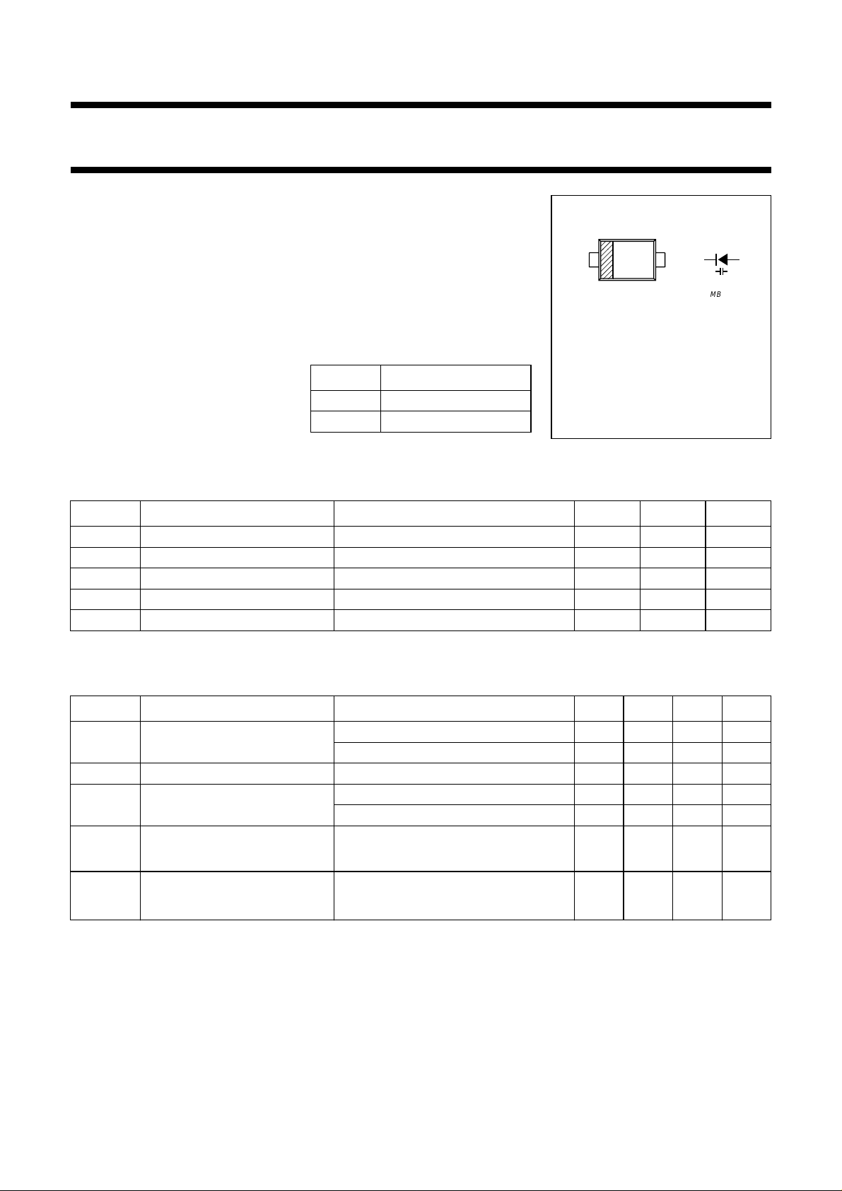
PINNING
PIN DESCRIPTION
1 cathode
2 anode
handbook, 2 columns
12
Y
MBK441
Marking code: Y.
Orientation of marking code as shown.
Cathode side indicated by a bar.
Fig.1 Simplified outline
(SOD523; SC-79) and symbol.
(VCO).
LIMITING VALUES
In accordance with the Absolute Maximum Rating System (IEC 134).
SYMBOL PARAMETER CONDITIONS MIN. MAX. UNIT
V
R
V
RM
I
F
T
stg
T
j
continuous reverse voltage − 34 V
peak reverse voltage in series with a 10 kΩ resistor − 35 V
continuous forward current − 20 mA
storage temperature −55 +150 °C
operating junction temperature −55 +150 °C
ELECTRICAL CHARACTERISTICS
Tj=25°C unless otherwise specified.
SYMBOL PARAMETER CONDITIONS MIN. TYP. MAX. UNIT
I
R
r
s
C
d
C
d2V()
------------------C
d25V()
C
∆
d
---------C
d
reverse current VR= 32 V; see Fig.3 −−10 nA
V
= 32 V; Tj=85°C; see Fig.3 −−200 nA
R
diode series resistance f = 470 MHz; VR=5V −−1.1 Ω
diode capacitance VR= 2 V; f = 1 MHz; see Figs 2 and 4 47 − 53 pF
= 25 V; f = 1 MHz; see Figs 2 and 4 2.65 − 3pF
V
R
capacitance ratio f = 1 MHz 17 −−
capacitance matching VR= 2 to 25 V; in a sequence of 15
−−2%
diodes (gliding)
1999 Sep 15 2
Philips Semiconductors Preliminary specification
VHF variable capacitance diode BB182B
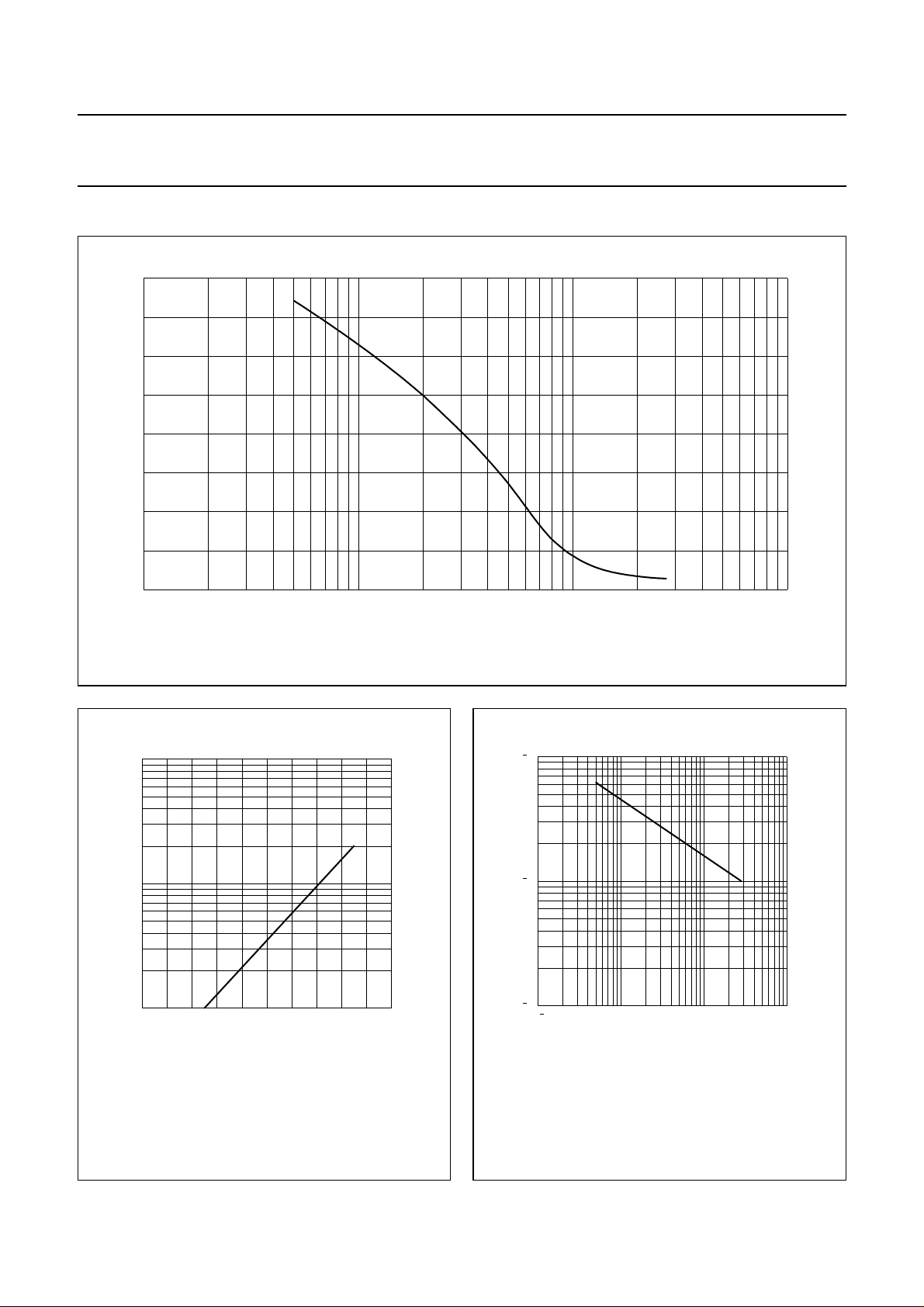
GRAPHICAL DATA
80
handbook, full pagewidth
C
d
(pF)
60
40
20
0
−1
10
f = 1 MHz; Tj=25°C.
1
10 10
VR (V)
Fig.2 Diode capacitance as a function of reverse voltage; typical values.
MCD783
2
3
10
handbook, halfpage
I
R
(nA)
2
10
10
50
o
T ( C)
j
Fig.3 Reversecurrentasafunctionofjunction
temperature; maximum values.
MLC816
V (V)
R
MLC815
2
3
10
handbook, halfpage
TC
d
(K−1)
4
10
5
10
1
1000
10
11010
Fig.4 Temperature coefficient of diode
capacitance as a function of
reverse voltage; typical values.
1999 Sep 15 3
 Loading...