

Philips 50FD9955 User Manual
Once your PHILIPS purchase is registered, you’re eligible to receive all the privileges of owning a
PHILIPS product. So complete and return the Warranty Registration Card enclosed with your
purchase at once, and take advantage of these important benefits.
Return your Warranty Registration card today to ensure
you receive all the
benefits
you’re entitled to.
For Customer Use
Enter below the Serial No., which is
located on the rear of the cabinet. Retain
this information for future reference.
Model No. __________________________
Serial No. __________________________
Congratulations on your purchase, and
welcome to the “family!”
Dear PHILIPS product owner:
Thank you for your confidence in PHILIPS.You’ve selected one of
the best-built, best-backed products available today.And we’ll do
everything in our power to keep you happy with your
purchase for many years to come.
As a member of the PHILIPS “family,” you’re entitled to
protection by one of the most comprehensive warranties and
outstanding service networks in the industry.
What’s more, your purchase guarantees you’ll receive all the
information and special offers for which you qualify, plus easy
access to accessories from our convenient home shopping
network.
And most importantly you can count on our uncompromising
commitment to your total satisfaction.
All of this is our way of saying welcome-and thanks for investing
in a PHILIPS product.
Sincerely,
Lawrence J. Blanford
President and Chief Executive Officer
P.S. Remember, to get the most from your PHILIPS
product, you must return your Warranty
Registration Card within 10 days. So please mail
it to us right now!
Know these
safety symbols
This “bolt of lightning” indicates
uninsulated material within your unit
may cause an electrical shock. For the
safety of everyone in your household, please
do not remove product
covering.
The “exclamation point” calls attention
to features for which you should read
the enclosed literature closely to
prevent operating and maintenance
problems.
WARNING:TO PREVENT FIRE OR
SHOCK HAZARD, DO NOT EXPOSE THIS
EQUIPMENT TO RAIN OR MOISTURE.
CAUTION: To prevent electric shock,
match wide blade of plug to wide slot, fully
insert.
ATTENTION:Pour éviter les choc
électriques, introduire la lame la plus large de
la fiche dans la borne correspondante de la
prise et pousser jusqu’au fond.
CAUTION
RISK OF ELECTRIC SHOCK
DO NOT OPEN
CAUTION: TO REDUCE THE RISK OF ELECTRIC SHOCK, DO NOT
REMOVE COVER (OR BACK). NO USER-SERVICEABLE PARTS
INSIDE. REFER SERVICING TO QUALIFIED SERVICE PERSONNEL.
R
E
G
I
S
T
R
A
T
I
O
N
N
E
E
D
E
D
W
I
T
H
I
N
1
0
D
A
Y
S
Hurry!
Warranty
Verification
Registering your product within
10 days confirms your right to
maximum protection under the
terms and conditions of your
PHILIPS warranty.
Owner
Confirmation
Your completed Warranty
Registration Card serves as
verification of ownership in the
event of product theft or loss.
Model
Registration
Returning your Warranty Registration
Card right away guarantees you’ll
receive all the information and special
offers which you qualify for as the
owner of your model.
Visit our World Wide Web Site at http://www.philips.com
t
s
EnglishFrançaisEspañol
1

IMPORTANT SAFETY INSTRUCTIONS
Read before operating equipment
1. Read these instructions.
2. Keep these instructions.
3. Heed all warnings.
4. Follow all instructions.
5. Do not use this apparatus near water.
6. Clean only with a dry cloth.
7. Do not block any of the ventilation openings. Install in
accordance with the manufacturers instructions.
8. Do not install near any heat sources such as radiators, heat
registers, stoves, or other apparatus (including amplifiers)
that produce heat.
9. Do not defeat the safety purpose of the polarized or
grounding-type plug. A polarized plug has two blades with
one wider than the other. A grounding type plug has two
blades and third grounding prong.The wide blade or third
prong are provided for your safety.When the provided plug
does not fit into your outlet, consult an electrician for
replacement of the obsolete outlet.
10. Protect the power cord from being walked on or pinched
particularly at plugs, convenience receptacles, and the point
where they exit from the apparatus.
11. Only use attachments/accessories specified by the
manufacturer.
12. Use only with a cart, stand,tripod, bracket, or
13. Unplug this apparatus during lightning storms or when
14. Refer all servicing to qualified service personnel. Servicing is
15. This product may contain lead or mercury. Disposal of these
table specified by the manufacturer, or sold with
the apparatus.When a cart is used, use caution
when moving the cart/apparatus combination to avoid injury
from tip-over.
unused for long periods of time.
required when the apparatus has been damaged in any way,
such as power-supply cord or plug is damaged, liquid has
been spilled or objects have fallen into apparatus, the
apparatus has been exposed to rain or moisture, does not
operate normally,or has been dropped.
materials may be regulated due to environmental
considerations. For disposal or recycling information, please
contact your local authorities or the Electronic Industries
Alliance: www.eiae.org.
16. Damage Requiring Service - The appliance should be
serviced by qualified service personnel when:
A. The power supply cord or the plug has been damaged;
or
B. Objects have fallen, or liquid has been spilled into the
appliance; or
C. The appliance has been exposed to rain; or
D. The appliance does not appear to operate normally or
exhibits a marked change in performance; or
E. The appliance has been dropped, or the enclosure
damaged.
17. Tilt/Stability - All televisions must comply with
recommended international global safety standards for tilt
and stability properties of its cabinets design.
• Do not compromise these design standards by applying
excessive pull force to the front,or top,of the cabinet
which could ultimately overturn the product.
• Also, do not endanger yourself, or children, by placing
electronic equipment/toys on the top of the cabinet.
Such items could unsuspectingly fall from the top of
the set and cause product damage and/or personal
injury.
18. Wall Mounting - The appliance should be mounted to a
wall only as recommended by the manufacturer.
19. Power Lines - An outdoor antenna should be located away
from power lines.
20. Outdoor Antenna Grounding - If an outside antenna is
connected to the receiver, be sure the antenna system is
grounded so as to provide some protection against voltage
surges and built up static charges.
Section 810 of the National Electric Code, ANSI/NFPA No.
70-1984, provides information with respect to proper
grounding of the mats and supporting structure grounding
of the lead-in wire to an antenna-discharge unit, size of
grounding connectors, location of antenna-discharge unit,
connection to grounding electrodes and requirements for
the grounding electrode. See Figure below.
21. Objects and Liquid Entry - Care should be taken so that
objects do not fall and liquids are not spilled into the
enclosure through openings.
Congratulations on purchasing this Philips product.
We’ve included everything you need to get started.
If you have any problems, Philips reprensatives can
help you get the most from your new product by explaining:
• Hookups
• First Time Setup, and
• Feature Operation.
For fast help, call us first !
1-800-531-0039
Thank you for making Philips a part of your home!
2
This symbol informs that there are contents that demand caution (including warnings).
This symbol indicates a prohibited matter.
This symbol indicates something that must be done.
Ignoring this indication and improper handling could be the
WARNING
When installing the plasma display or making angle adjustments, be sure to make a request for service
with the dealer and ensure the work is performed according to this manual.Incorrect installation and
angle adjustments may result in the plasma display falling and causing injury.
To prevent the plasma display from falling, the strength of the installation place and the method of
fastening must support the combined weight of the plasma display and the mounting unit for an
extended period of time as well as withstand earthquakes. Improper installation may result in the plasma
display falling and causing injury. Be sure to observe the following matters.
- An electrical outlet should be used for the power supply of the plasma display. Direct connection to a
power cable is dangerous and should not be used. Please use a power outlet that can be reached to
allow the insertion and withdrawal of the power plug.
- Installation for Wooden Walls:The load should by all means be carried by beams, and when the
strength of the beams is insufficient, they should be strengthened.The installation should not be made
to skirting or supporting members. The load should also be carried by beams when there is a steel
beam suspended ceiling; installation should not be made to the ceiling suspension fittings.
- Installation for Concrete Walls: Commercial anchors that are strong enough to easily support the load
of the plasma display should be used.
- Not for use in a computer room as defined in the Standard for the Protection of Electronic
Computer/Data Processing Equipment ANSI/NFPA 75.
To ensure safety, bolts and screws must be tightened securely. Be sure to use the supplied parts for the
brackets and the other fittings. Failure to do so may result in the plasma display falling and causing injury.
When aligning the grooves of the display fittings to the fixed unit, check to make sure that they are
securely engaged. Failure to do so may result in the plasma display falling and causing injury.
Do not modify any parts. Failure to do so may result in the plasma display falling and causing injury.
Do not use any damaged parts. Failure to do so may result in the plasma display falling and causing
injury. In the event that any parts are damaged, please contact the dealer.
This plasma display mounting unit is for use only with PHILIPS 50 inch plasma displays. Do not use with
any other equipment since the equipment could fall and cause injury.
WARNING
cause of personal injury such as a serious injury or death.
Ignoring this indication and improper handling could cause injury
to a person or damage to the surrounding household belongings.
Do not obstruct the ventilation holes of the plasma display. Doing so will prevent the dissipation of heat
and may result a fire. Do not use the plasma display in the following ways:
Do not install the plasma display in a tight place where ventilation is poor, place a cover on it, etc.
Do not install the plasma display in front of the vents of an air conditioner or heater, or in a place
where there is strong vibration. Doing so may result in fire or electrical shock.
Do not install the plasma display in humid or dusty places, or where it will be exposed to greasy smoke
or steam (such as near cooking equipment or humidifiers). Doing so may result in a fire. Do not use the
plasma display outdoors. Doing so may result in a fire or electrical shock.
The plasma display shall not be exposed to dripping or splashing and no objects filled with liquids, such
as vases, shall be placed on it.
Leave sufficient space around the plasma display when installing it.
Failure to do so may load to head buildup within the display and could result in fire.
Hold the plasma display in place while attaching it to the unit. Failing to do so may lead to it falling and
causing injury.
Installation Location
Avoid rooms with a lot of dust, humidity, greasy smoke, or tobacco smoke.
Dirt will adhere to the surface of the display monitor screen and cause a deterioration in image quality.
Avoid places in which the screen is exposed to direct sunlight or illumination light.
When surrounding light hits the screen directly, the image appears washed out and is difficult to view.
Avoid places which reach high temperatures or low temperatures.
Such extreme temperatures will cause breakdown.
3
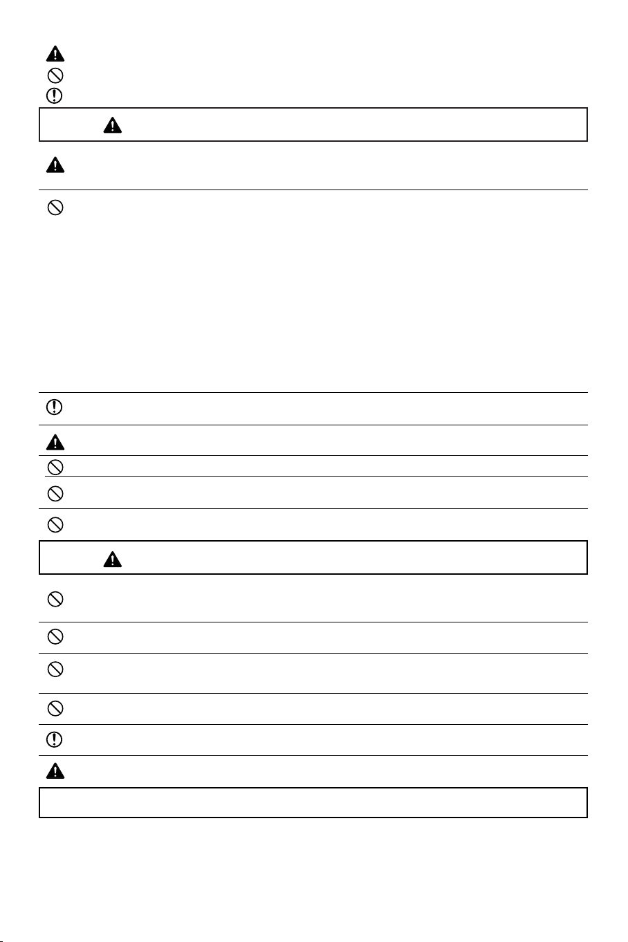
Unpacking and wall mounting instructions
Protective sheet
round hole
square hole
Special technology is required in the mounting of the plasma display.
Such work should never be undertaken by the customer.
For the safety of the customer, we ask that the installation work be started after careful attention is
paid to the strength of the mounting location to be sure it will withstand the weight (about 97 Lbs) of
the plasma display and mounting hardware.
Be sure that two or more persons engage in the installation work.
Be careful not to lose any of the removed screws or other parts.
Remove the packaging
& Open the upper carton which packages the
plasma display and remove the styrofoam.
é Remove the upper carton and open the
protective sheet.
Package parts list
wall mount unit
M4 screws x 4
Attach the display fittings
“ With the display standing in its packaging
carton, align the square holes of the display
fittings with the screw holes of the plasma
display, then fasten the display fittings using the
supplied screws.
Installation of the display fittings can also be
performed by laying down the plasma display
on a flat surface.
Remove the plasma display form the carton,
place the protective sheet that was used in the
packaging on a flat surface (which is larger than
the display), then lay the display down on top of
this with the screen surface facing downward.
display fittings
4
M4 screws x 8
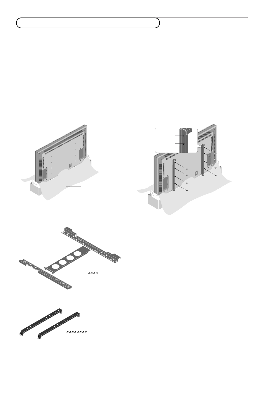
Assembling and mounting the wall mount unit
& Securely fasten the upper and lower wall-side
fittings to the middle wall-side fitting with the
four supplied M4 screws.
é Fasten the unit with commercial anchors or the
four screws. Be sure that the anchors or
screws are fastened at a position where there
is a post.
Note:
Use anchors and screws to suit the various wall
types.The enclosed template can be used for
general positioning only.
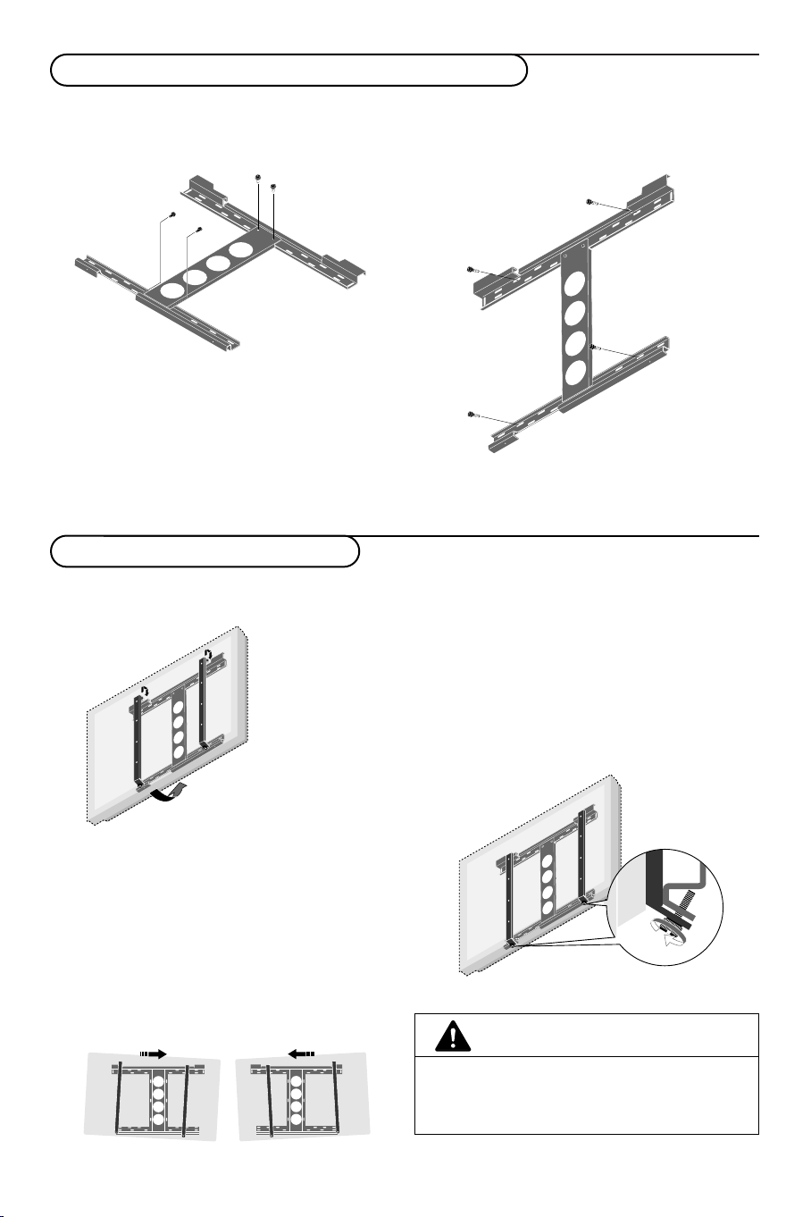
Mounting the plasma display
& Mount the display (to which the display fittings
have already been attached) to the wall
mounting unit.
Make sure that the wall mount unit is being
fixed securely enough so that it meets safety
standards.
“ Anchor the plasma display.
Align the thumb screw, which is located at the
bottom of the display fitting, with the hole of
the (lower) wall-side fitting and tighten to
anchor.
Fasten securely until the screw ceases to turn.
To r emove the display, loosen the thumb
screws until they come out of the hole.
Pull the bottom portion of the display towards
you and lift upward to release the display.
é Fit the upper hooks of the display fittings into
the grooves of the (upper) wall fittings and
adjust for level positioning.
Note: It is recommended that the power cable and
various signal cables be plugged into the display
before mounting the display.After mounting the
display, plugging in the cables may be difficult.
If the display is tilted to the left or right, the
display fitting is not properly placed on the wall
mounting unit. Slide in the direction of the
lower side and adjust for level positioning.
CAUTION
Firmly support the display when mounting it.
Failure to do so may result in the plasma display
falling and causing injury.
5
5

CVBS 1
CVBS 2
Y/C
VGA
R/Cr/Pr
Y
Cb/Pb
Cr/Pr
DVD/HD
RGB/DVD/HD
EXTERNAL
CONTROL
G/Y
B/Cb/Pb
HD
DVI
VD
Connect Peripheral Equipment
You may connect 2 possible VGA sources (VGA or RGB
Digital (DVI)) and 3 possible video sources (AV1,AV2 and
AV3) to the right side of the monitor.
AV1 Connect VCRs, DVDs or Laser Discs, etc. here.
CVBS 1 : BNC connector for Video CVBS
or
CVBS 2 : cinch connector for Video CVBS
or
Y/C 3 : S-Video connector for Y/C-SVHS video.
AV2 Connect DVD, HD, DTV or Laser Discs, etc. with
YPbPr connectors.
AV3 Connect DVDs, HD or Laser Discs, etc. here.
Use the 5 BNC connectors for RGB input.
Use the R/PrG/YB/Pb connectors for component input.
VGA Input for analog RGB signal of PC, etc.
DVI Inputs a PC with a digital RGB signal or equipment
(STB, DVD,...) with a digital interface compliant with
the DVI standard.
RS 232c Serial I/O port
This connector allows you to control your monitor via
external equipment (e.g. PC) and a replacement of the
remote control
6
Connect your computer
R6 / AA
Note:When you connect a computer to this monitor, attach the supplied ferrite cores. If you do not do this, this
monitor will not comply with the mandatory CE or C-Tick standards.
& Set the (large) ferrite core on one end of the power cable (supplied).
é In case of a computer with a digital RGB output set the (small) ferrite cores on both ends of the DVI
cable (not supplied).
“ Click the lids tightly until the clamps click.
‘ Use the bands to secure the ferrite cores.
Directly to the plasma display
& Connect one end of a VGA cable supplied to
the video card of the computer and the other
end to the
case of a computer with a digital
VGA (or to RGB Digital DVI in
RGB output)
connector at the right side of the monitor. Fix
the connectors firmly with the screws on the
plug. See Table of Signals Supported, p. 19.
é In case of a Multimedia computer, connect the
audio cable to the
computer and to the
AUDIO outputs of your
AUDIO inputs of an
additional audio receiver.
Operation
Power On/Off
Mains inlet
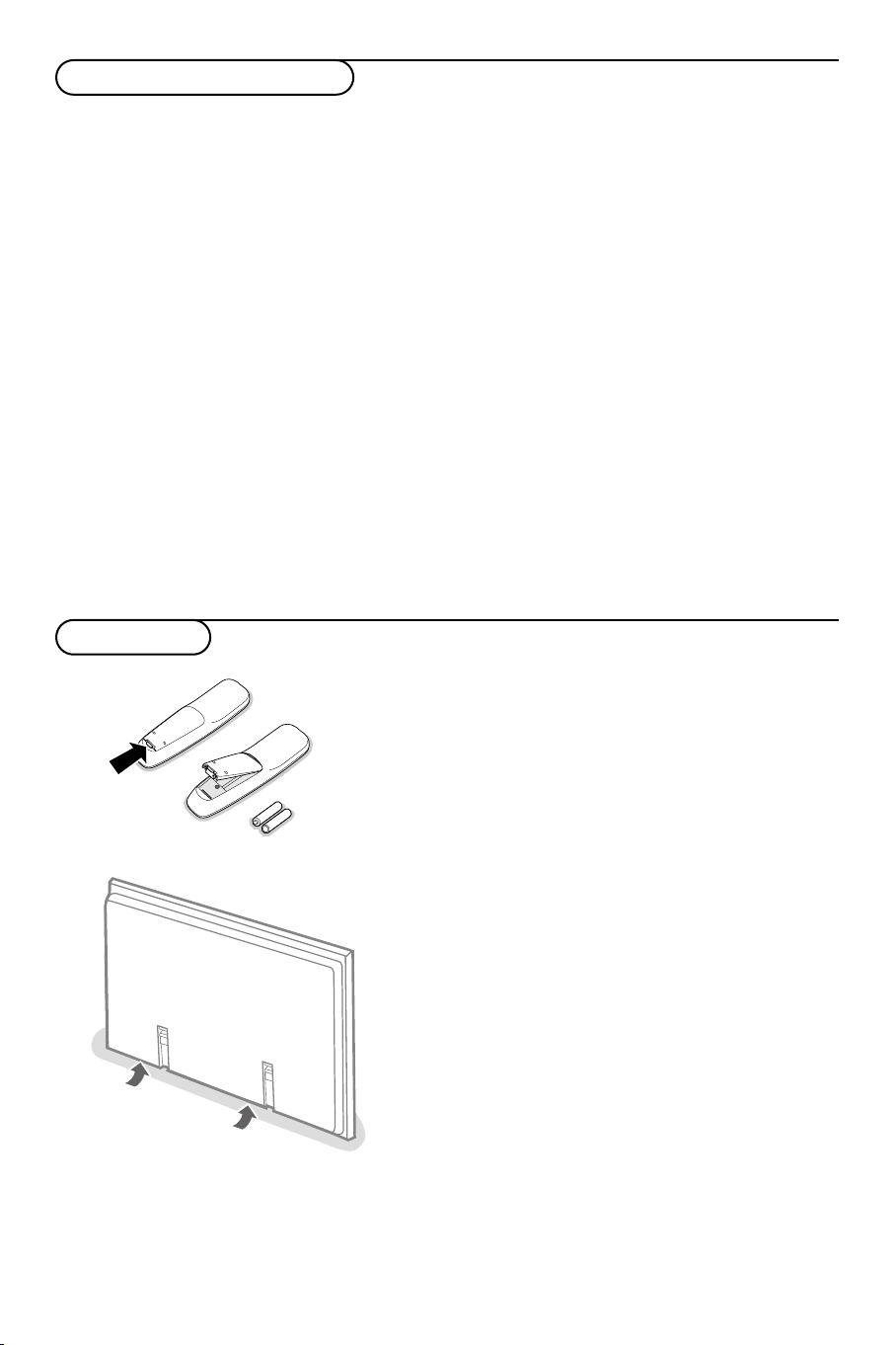
& Insert the mains plug supplied into the mains inlet at
é Remote control:remove the cover of the battery
“ Make sure that your receiver box and/or PC are
‘ Switch the plasma display on :
To an electronic receiver box
See the handbook of the receiver box.
& Connect one end of a VGA cable to the video
card of the computer and the other end to the
VGA IN connector at the rear side of the
receiver box. Fix the connectors firmly with the
screws on the plug.
é In case of a Multimedia computer, connect the
audio cable to the
computer and to the
and
L (left) inputs of the receiver box.
AUDIO outputs of your
AUDIO VGA IN R (right)
the bottom of the monitor and in the wall socket. For
safety, please, only use the supplied rim-earthed mains
cord which has to be inserted in a grounded socket.
compartment.
In
sert the 2 batteries supplied (Type LR6/AA-1.5V).
The batteries supplied do not contain the heavy metals
mercury and cadmium. Nevertheless in many countries
batteries may not be disposed of with your household waste.
Please check on how to dispose of batteries according to
local regulations.
switched on and that your PC is in the correct display
mode (see p. 19).
Press the power button B at the bottom side of the
monitor.
A green indicator lights up and the screen comes on.
When the plasma display does not receive a supported
vga signal or is not connected to a receiver box, the
screen switches to standby and the red indicator lights
up.
Warning:The Power On/Off switch does not
disconnect the plasma display completely from the
mains.
7
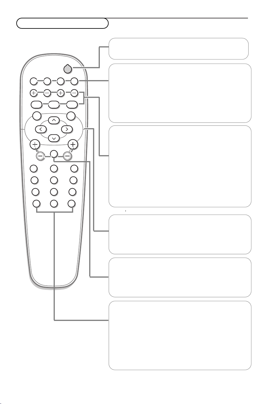
Use of the remote control
POWER
BRIGHTNESS
CONTRAST
ZOOM OUTZOOM INZOOM ON/OFF
VGA AV1 AV2 AV3
MUTE
AV MUTE
q
1
2
3
4
5
6
7
8
9
0
V
CH/PR
MENU
OK
¬
B
B To s witch to standby or on again (Does not operate when
POWER/STANDBY indicator of the plasma display is off).
VGA
Press repeatedly to select your computer connected to the
VGA or to the DVI (digital RGB) connector.
AV1,AV2,AV3
Press to select the peripherals connected to one of the
VIDEO connectors (AV 1), to the COMPONENT INPUT
(AV2) (Y/CbPb/CrPr) or RCrPr/Gy/BCbPb/Hd/Vd
(
AV3 ) connectors.
BRIGHTNESS +/-
To adjust the brightness level of the picture
CONTRAST +/-
To adjust the contrast level of the picture
ZOOM ON/OFF
To activate/de-activate the zoom function.
ZOOM IN/OUT
To adjust the zoom factor and to change the magnification of
the picture when zoom is activated.
Note: not possible with a 2.35:1 picture format.
MENU
To s witch the menu on/off
Cursor buttons
To select your choice and to alter a selected adjustment.
OK To activate your choice
V
No function
¬ Mute button
No function
CH/PR Program selection
To browse through the sources selected.
AV MUTE
To m ute the picture or restore it if the plasma display is used
in the
VGA mode.
When activated a green indicator starts blinking in front of
the plasma display.
q Picture format
Press the
q button to switch between the different picture
formats.
Note: do not allow the displayed in 4:3 mode for an extended
period.This can cause a phosphor burn-in.
8
 Loading...