

Philips 20PF8846-98 User Manual
LCD TV Quick Use Guide
3139 125 33551
Thank you for purchasing this Philips LCD Television set. You are now
the proud owner of a LCD TV set which promises full value to you as
a customer. Before you proceed to install the LCD TV, please follow the
steps and diagrams as shown to familiarise yourself with the correct and
safe way of assembling the stand to the TV.
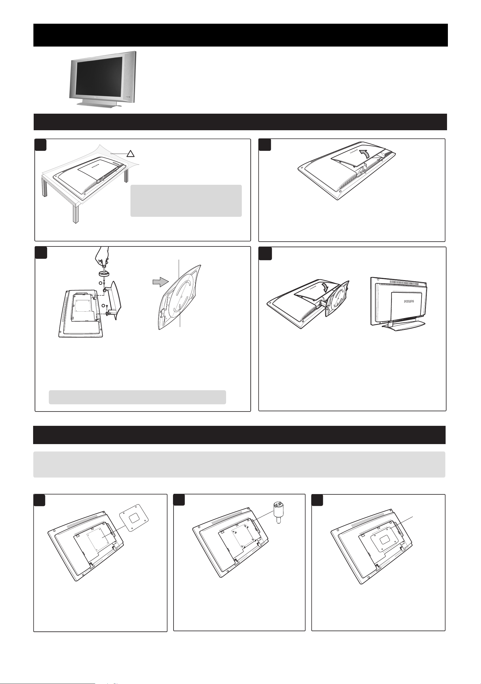
ASSEMBLING THE STAND
1
3
2
!
Ensure you have the following before
you assemble the stand :
– Two screws (supplied with set)
– One Screwdriver (not supplied)
Place the set facing down on a protective
sheet close to the edge of a flat surface.
Bottom of swivel base
1
2
Open back plate cover by gently pulling upwards.
4
Align arrow
to the center
For swivelling of the stand to function properly, adjust the swivel base at
the back of the stand until arrow is aligned in the center. Align the stand
studs into the holes at the bottom of the set. Put in the screws (provided)
into the 2 holes and tightened with a screwdriver.
CAUTION : While putting in the screws, hold onto the stand.
Close back plate cover by gently
pushing the cover downwards.
INSTALLING LCD TV ON THE WALL
If you intend to install the LCD TV on the wall. ensure you have the following :
– Standard VESA 100 bracket for LCD TV (not supplied) and four spacers found in the accessory bag.
Do the following when installing the LCD TV on the wall :
Check the stand arm is rigid and
properly installed. Place the
set upright.
1
Ñ
If your VESA bracket does not fit into the slot
at the rear of the LCD TV, proceed to make
use of the four spacers provided. Note : If VESA
bracket fits into the slot, you need not use the
spacers.
VESA
Bracket
does not
fit
2
Ñ
Screw the four spacers to the holes at the
rear of the set. Ensure the spacers are
properly tightened (torque of 1.2N-m or
1 lbf-in).
Spacer
x 4
3
Ñ
Place the VESA bracket on the spacers and
tightened with the VESA bracket screws.
Tighten
VESA
bracket
to spacers
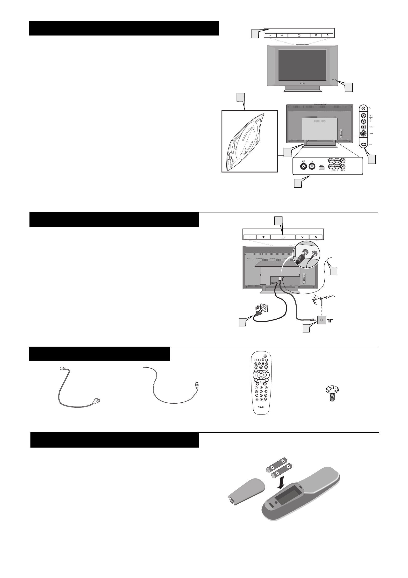
PRESENTATION OF THE LCD TELEVISION
FM ANT
:
Television keys
1
¥ 2 : to switch the TV on or off.
• VOLUME + / – : to adjust sound level.
• PROGRAM + /– : to select programmes.
To access or close menus, press the VOLUME + / – keys simultaneously.
The PROGRAM + / – keys can be used to select an adjustment and the
VOLUME + / – keys make that adjustment.
Adjustable stand
2
The stand has swivel and tilt functions. For swivelling function, ensure the arrows
at the bottom of the stand arm and the swivel base are aligned in the center (see
diagram on the right). For tilting function, you can tilt the set backward or forward
to your preferred angle.
Note : The stand can be removed and the LCD TV can be installed on the wall.
This set has four mounting interfaces fulfilling VESA specifications. Pull out the
back plate cover to access the four installing interfaces. Installation of the LCD
TV on the wall should be carried out by qualified servicemen.Improper or
incorrect installation may render the set unsafe.
LED light and infrared sensors
3
Aim remote control at infrared sensors to activate TV controls.
Rear connectors
4
Located at the rear of the set.
Bottom connectors
Located at the bottom of the set.
5
2
1
Bottom of
swivel base
VOLUME
2
5
PROGRAM
3
L
R
4
BASIC LCD TV INSTALLATION
Gently pull out the cover to locate all the sockets at the bottom of the set.
Use the aerial connection lead (not supplied) and connect the aerial
socket of the TV to the ¬ socket.
1
Insert the radio aerial lead supplied into the FM ANT socket of
the TV.
2
Connect the mains cord to the television power inlet and the
mains plug into the wall socket.
3
Press the 2 button to switch on the television set.
4
L
ISTING THE
A
CCESSORIES
3
VOLUME
Wall socket
4
PROGRAM
L
R
Aerial socket
1
FM ANTENNA
2
TV mains cord
FM radio aerial lead
REMOTE CONTROL OPERATION
Do the following steps to ensure that your remote control is ready for operation.
Pull out the battery cover.
1
Place the two batteries in the remote. Be sure the (+) and (–)
ends of the batteries line up correctly (the inside of the case is
2
marked).
Insert battery cover and the remote control is now ready for use.
3
Note : The battery supplied with the set does not contain mercury
or nickel cadmium so as to protect the environment. When discarding
your batteries, use the recycling options available.
Remote Control
Screw (x 2)
2
 Loading...