


 Loading...
OPERATING INSTRUCTIONS
EN
Translation of the original instructions
HIPACE 300 M
Turbopump
PT 0330 BEN/E (1711)

Table of contents
Table of contents
1 About this manual . . . . . . . . . . . . . . . . . . . . . . . . . . . . . . . . . . . . . . . . . . . . . . . 4
1.1 Validity. . . . . . . . . . . . . . . . . . . . . . . . . . . . . . . . . . . . . . . . . . . . . . . . . . . . . 4 1.1.1 Applicable documents . . . . . . . . . . . . . . . . . . . . . . . . . . . . . . . . . . . 4 1.2 Conventions . . . . . . . . . . . . . . . . . . . . . . . . . . . . . . . . . . . . . . . . . . . . . . . . 4 1.2.1 Safety instructions. . . . . . . . . . . . . . . . . . . . . . . . . . . . . . . . . . . . . . 4 1.2.2 Pictographs . . . . . . . . . . . . . . . . . . . . . . . . . . . . . . . . . . . . . . . . . . . 5 1.2.3 Instructions in the text . . . . . . . . . . . . . . . . . . . . . . . . . . . . . . . . . . . 5 1.2.4 Abbreviations . . . . . . . . . . . . . . . . . . . . . . . . . . . . . . . . . . . . . . . . . 5 1.2.5 Symbols used . . . . . . . . . . . . . . . . . . . . . . . . . . . . . . . . . . . . . . . . . 5
2 Safety . . . . . . . . . . . . . . . . . . . . . . . . . . . . . . . . . . . . . . . . . . . . . . . . . . . . . . . . . 6
2.1 Safety precautions . . . . . . . . . . . . . . . . . . . . . . . . . . . . . . . . . . . . . . . . . . . 6 2.2 Protective equipment . . . . . . . . . . . . . . . . . . . . . . . . . . . . . . . . . . . . . . . . . 7 2.3 Proper use . . . . . . . . . . . . . . . . . . . . . . . . . . . . . . . . . . . . . . . . . . . . . . . . . 7 2.4 Improper use. . . . . . . . . . . . . . . . . . . . . . . . . . . . . . . . . . . . . . . . . . . . . . . . 8
3 Transport and storage. . . . . . . . . . . . . . . . . . . . . . . . . . . . . . . . . . . . . . . . . . . . 9
3.1 Transport. . . . . . . . . . . . . . . . . . . . . . . . . . . . . . . . . . . . . . . . . . . . . . . . . . . 9 3.2 Storage . . . . . . . . . . . . . . . . . . . . . . . . . . . . . . . . . . . . . . . . . . . . . . . . . . . . 9
4 Product description. . . . . . . . . . . . . . . . . . . . . . . . . . . . . . . . . . . . . . . . . . . . . 10
4.1 Product identification. . . . . . . . . . . . . . . . . . . . . . . . . . . . . . . . . . . . . . . . . 10 4.1.1 Pump types . . . . . . . . . . . . . . . . . . . . . . . . . . . . . . . . . . . . . . . . . . 10 4.1.2 Pump features. . . . . . . . . . . . . . . . . . . . . . . . . . . . . . . . . . . . . . . . 10 4.1.3 Scope of delivery. . . . . . . . . . . . . . . . . . . . . . . . . . . . . . . . . . . . . . 10 4.2 Function . . . . . . . . . . . . . . . . . . . . . . . . . . . . . . . . . . . . . . . . . . . . . . . . . . 11 4.2.1 Cooling . . . . . . . . . . . . . . . . . . . . . . . . . . . . . . . . . . . . . . . . . . . . . 11 4.2.2 Rotor bearing . . . . . . . . . . . . . . . . . . . . . . . . . . . . . . . . . . . . . . . . 11 4.2.3 Drive . . . . . . . . . . . . . . . . . . . . . . . . . . . . . . . . . . . . . . . . . . . . . . . 11
4.3 Range of application . . . . . . . . . . . . . . . . . . . . . . . . . . . . . . . . . . . . . . . . . 12
5 Installation . . . . . . . . . . . . . . . . . . . . . . . . . . . . . . . . . . . . . . . . . . . . . . . . . . . . 13
5.1 Preparatory work. . . . . . . . . . . . . . . . . . . . . . . . . . . . . . . . . . . . . . . . . . . . 13 5.2 Set-up . . . . . . . . . . . . . . . . . . . . . . . . . . . . . . . . . . . . . . . . . . . . . . . . . . . . 13 5.2.1 Earthquake safety . . . . . . . . . . . . . . . . . . . . . . . . . . . . . . . . . . . . . 13 5.2.2 Use of a splinter shield or protection screen . . . . . . . . . . . . . . . . . 14 5.2.3 Vibration damper. . . . . . . . . . . . . . . . . . . . . . . . . . . . . . . . . . . . . . 14 5.3 Mounting orientation . . . . . . . . . . . . . . . . . . . . . . . . . . . . . . . . . . . . . . . . . 15
5.4 Connecting the high vacuum side. . . . . . . . . . . . . . . . . . . . . . . . . . . . . . . 16 5.4.1 Installation of ISO-K flange with ISO-K flange . . . . . . . . . . . . . . . 16 5.4.2 Installation of ISO-K flange with ISO-F flange. . . . . . . . . . . . . . . . 17 5.4.3 Installation of ISO-F with ISO-F flange . . . . . . . . . . . . . . . . . . . . . 18 5.4.4 Installation of CFflanges . . . . . . . . . . . . . . . . . . . . . . . . . . . . . . . 19
5.5 Connecting the fore-vacuum side . . . . . . . . . . . . . . . . . . . . . . . . . . . . . . . 20 5.6 Connections to the turbopump . . . . . . . . . . . . . . . . . . . . . . . . . . . . . . . . . 21 5.6.1 Electronic drive unit. . . . . . . . . . . . . . . . . . . . . . . . . . . . . . . . . . . . 21 5.6.2 Earthing. . . . . . . . . . . . . . . . . . . . . . . . . . . . . . . . . . . . . . . . . . . . . 21 5.6.3 Power and electrical supply . . . . . . . . . . . . . . . . . . . . . . . . . . . . . 21 5.7 Accessory connection . . . . . . . . . . . . . . . . . . . . . . . . . . . . . . . . . . . . . . . . 22 5.7.1 Venting valve. . . . . . . . . . . . . . . . . . . . . . . . . . . . . . . . . . . . . . . . . 23 5.7.2 Air cooling . . . . . . . . . . . . . . . . . . . . . . . . . . . . . . . . . . . . . . . . . . . 23 5.7.3 Sealing gas connection . . . . . . . . . . . . . . . . . . . . . . . . . . . . . . . . . 24 5.7.4 Heating jacket . . . . . . . . . . . . . . . . . . . . . . . . . . . . . . . . . . . . . . . . 24 5.7.5 Water cooling . . . . . . . . . . . . . . . . . . . . . . . . . . . . . . . . . . . . . . . . 26
6 Operation . . . . . . . . . . . . . . . . . . . . . . . . . . . . . . . . . . . . . . . . . . . . . . . . . . . . . 27
2

Table of contents
6.1 Commissioning . . . . . . . . . . . . . . . . . . . . . . . . . . . . . . . . . . . . . . . . . . . . . 27 6.1.1 Magnetic bearing calibration . . . . . . . . . . . . . . . . . . . . . . . . . . . . . 27 6.2 Operation modes . . . . . . . . . . . . . . . . . . . . . . . . . . . . . . . . . . . . . . . . . . . 28
6.3 Function description . . . . . . . . . . . . . . . . . . . . . . . . . . . . . . . . . . . . . . . . . 28 6.3.1 Operation via "remote" connection . . . . . . . . . . . . . . . . . . . . . . . . 28 6.3.2 Operation with DCU or HPU . . . . . . . . . . . . . . . . . . . . . . . . . . . . . 28 6.3.3 Operation via fieldbus . . . . . . . . . . . . . . . . . . . . . . . . . . . . . . . . . . 28 6.4 Monitoring of the operation conditions . . . . . . . . . . . . . . . . . . . . . . . . . . . 28 6.4.1 Temperature monitoring . . . . . . . . . . . . . . . . . . . . . . . . . . . . . . . . 28 6.4.2 Operation display via LED. . . . . . . . . . . . . . . . . . . . . . . . . . . . . . . 29 6.4.3 Safety bearing stress . . . . . . . . . . . . . . . . . . . . . . . . . . . . . . . . . . 29 6.4.4 Balance . . . . . . . . . . . . . . . . . . . . . . . . . . . . . . . . . . . . . . . . . . . . . 29
6.5 Switching off and venting . . . . . . . . . . . . . . . . . . . . . . . . . . . . . . . . . . . . . 29 6.5.1 Switching off . . . . . . . . . . . . . . . . . . . . . . . . . . . . . . . . . . . . . . . . . 29 6.5.2 Electrical brake . . . . . . . . . . . . . . . . . . . . . . . . . . . . . . . . . . . . . . . 29 6.5.3 Emergency power supply . . . . . . . . . . . . . . . . . . . . . . . . . . . . . . . 30 6.5.4 Venting . . . . . . . . . . . . . . . . . . . . . . . . . . . . . . . . . . . . . . . . . . . . . 30
7 Maintenance / replacement. . . . . . . . . . . . . . . . . . . . . . . . . . . . . . . . . . . . . . . 31
7.1 Maintenance intervals and responsibilities . . . . . . . . . . . . . . . . . . . . . . . . 31 7.2 Replacing the electronic drive unit . . . . . . . . . . . . . . . . . . . . . . . . . . . . . . 31 7.2.1 Magnetic bearing calibration . . . . . . . . . . . . . . . . . . . . . . . . . . . . . 32 7.2.2 Rotation speed set value. . . . . . . . . . . . . . . . . . . . . . . . . . . . . . . . 32
8 Decommissioning . . . . . . . . . . . . . . . . . . . . . . . . . . . . . . . . . . . . . . . . . . . . . . 33
8.1 Shutting down for longer periods . . . . . . . . . . . . . . . . . . . . . . . . . . . . . . . 33 8.2 Re-starting . . . . . . . . . . . . . . . . . . . . . . . . . . . . . . . . . . . . . . . . . . . . . . . . 33 8.3 Disposal . . . . . . . . . . . . . . . . . . . . . . . . . . . . . . . . . . . . . . . . . . . . . . . . . . 33
9 Malfunctions . . . . . . . . . . . . . . . . . . . . . . . . . . . . . . . . . . . . . . . . . . . . . . . . . . 34
9.1 Rectifying malfunctions . . . . . . . . . . . . . . . . . . . . . . . . . . . . . . . . . . . . . . . 34
10 Service . . . . . . . . . . . . . . . . . . . . . . . . . . . . . . . . . . . . . . . . . . . . . . . . . . . . . . . 35 11 Spare parts HiPace 300 M . . . . . . . . . . . . . . . . . . . . . . . . . . . . . . . . . . . . . . . . 36 12 Accessories . . . . . . . . . . . . . . . . . . . . . . . . . . . . . . . . . . . . . . . . . . . . . . . . . . . 37 13 Technical data and dimensions . . . . . . . . . . . . . . . . . . . . . . . . . . . . . . . . . . . 39
13.1 General . . . . . . . . . . . . . . . . . . . . . . . . . . . . . . . . . . . . . . . . . . . . . . . . . . . 39 13.2 Technical data . . . . . . . . . . . . . . . . . . . . . . . . . . . . . . . . . . . . . . . . . . . . . . 39 13.3 Dimensions . . . . . . . . . . . . . . . . . . . . . . . . . . . . . . . . . . . . . . . . . . . . . . . . 41
Declaration of conformity . . . . . . . . . . . . . . . . . . . . . . . . . . . . . . . . . . . . . . . . 42
3
About this manual
1 About this manual
1.1Validity
This operating manual is for customers of Pfeiffer Vacuum. It describes the functioning of the designated product and provides the most important information for safe use of the unit. The description follows applicable EU guidelines. All information provided in this operating manual refers to the current state of the product's development. The documentation remains valid as long as the customer does not make any changes to the product.
Up-to-date operating instructions can also be downloaded from www.pfeiffer-vacuum.com.
1.1.1 Applicable documents
HiPace 300 M, depending on the model |
Operating instructions |
Operating instructions "Electronic drive unit TM 700", standard |
PT 0329 BN* |
Operating instructions "Electronic drive unit TM 700 PB", Profibus |
PT 0354 BN* |
Operating instructions "Electronic drive unit TM 700 E74", acc. Semi E74 |
PT 0355 BN* |
Operating instructions "Electronic drive unit TM 700 DN", DeviceNet |
PT 0356 BN* |
Operating instructions "Electronic drive unit TM 700 EC", EtherCAT |
PT 0503 BN* |
Declaration of conformity |
Part of this document |
*also available via www.pfeiffer-vacuum.com |
|
1.2Conventions
1.2.1Safety instructions
The safety instructions in Pfeiffer Vacuum operating instructions are the result of risk evaluations and hazard analyses and are oriented on international certification standards as specified by UL, CSA, ANSI Z-535, SEMI S1, ISO 3864 and DIN 4844. In this document, the following hazard levels and information are considered:
DANGER
Imminent danger
Indicates an imminent hazardous situation that will result in death or serious injury.
WARNING
Possibly imminent danger
Indicates an imminent hazardous situation that can result in death or serious injury.
CAUTION
Possibly imminent danger
Indicates an imminent hazardous situation that can result in minor or moderate injury.
NOTICE
Command or note
Command to perform an action or information about properties, the disregarding of which may result in damage to the product.
4

About this manual
1.2.2Pictographs
Prohibition of an action to avoid any risk of accidents, the disregarding of which may result in serious accidents
Warning of a displayed source of danger in connection with operation of the unit or equipment
Command to perform an action or task associated with a source of danger, the disregarding of which may result in serious accidents
Important information about the product or this document
1.2.3Instructions in the text
Work instruction: here you have to do something.
1.2.4Abbreviations
DCU: |
Display Control Unit |
HPU: |
Handheld Programming Unit |
TM: |
Electronic drive unit and magnetic bearing controller for turbopump |
TPS: |
Mains pack |
1.2.5Symbols used
The following symbols are used consistently throughout the diagrams:
High vacuum flange
Fore-vacuum flange
V Vacuum flange of the backing pump
Exhaust flange of the backing pump
Electrical connection
Sealing gas connection
Venting connection
Cooling water connection
5
Safety
2 Safety
2.1Safety precautions
Duty to inform
Each person involved in the installation, operation or maintenance of the vacuum pump must read and observe the safety-related parts of these operating instructions.
The operator is obligated to make operating personnel aware of dangers originating from the vacuum pump, the pumped medium and the entire system.
Installation and operation of accessories
Pfeiffer Vacuum pumps can be equipped with a series of adapted accessories. The installation, operation and maintenance of connected devices are described in detail in the operating instructions of the individual components.
For information on order numbers of components, see "Accessories".
Use original accessory parts only.
NOTICE
Checking the safety system against excess rotation speed
To provide the functioning of the integrated safety system for avoiding excess rotation speed, the pump must run-up from the standstill at least once a year.
Switch off the pump and await the complete standstill (rotation speed = 0 Hz).
Run-up the pump according to this operating instructions.
WARNING
Danger of unsafe electrical installation
Safe operation after installation is the responsibility of the operator.
Do not independently modify or change the pump and electrical equipment.
Make sure that the system is integrated in an emergency off safety circuit.
Consult Pfeiffer Vacuum for special requirements.
WARNING
Danger due to lack of power disconnection device
Pump and electronic drive unit are not equipped with a power disconnection device. Installation of a user-supplied power disconnection device in accordance with SEMI-S2.
Fit a circuit breaker with an interruption rating of min. 10,000 A.
WARNING
Danger of electric shock
In case of defect, the parts connected to the mains supply are under voltage.
Always keep the mains connection freely accessible so that you can disconnect it at any time.
●Do not expose any body parts to the vacuum.
●Observe all safety and accident prevention regulations.
●Regularly check the proper observance of all safety measures.
●Power supply: The turbopump power supply must apply to the requirements of double insulation between mains input voltage and operating voltage according to the regulations of IEC 61010 and IEC 60950. Therefore Pfeiffer Vacuum recommends to use exclusively original-power packs and -accessories. Only in this case Pfeiffer Vacuum is able to guarantee the compliance of the European and North American guidelines.
●A safe connection to the protective earthing conductor (PE) is recommended (protection class III).
6

Safety
●Do not loosen any plug connection during operations.
●Wait for the rotor to reach standstill before peforming work on the high vacuum flange.
●Keep leads and cables well away from hot surfaces (> 70 °C).
●Never fill or operate turbopump with cleaning agent.
●Do not operate the turbopump with open high vacuum flange.
●Do not carry out any unauthorized modifications or conversions to the pump.
●When returning the turbopump observe the shipping instructions.
2.2Protective equipment
Determined situations concerning the handling of vacuum pumps require wearing of personal protective equipment. The owner, respectively the employer are obligated to provide an adequate equipment to any operating persons.
DANGER
Danger to health by hazardous substances during maintenance or installation
Depending on the process vacuum pumps, components or operating fluids can be contaminated by toxic, reactive or radioactive substances.
Wear adequate protective equipment during maintenance and repairs or in case of reinstallation.
kg
WARNING
Risk of injury through falling objects
When transporting vacuum pumps by hand, there is a danger through loads slipping and falling down.
Carry small and mid-size vacuum pumps two-handed.
Carry vacuum pumps > 20 kg by a suitable lifting device.
Wear safety shoes with steel toe cap according to directive EN 347.
CAUTION
Risk of injury through hot surfaces
Vacuum pumps can become hot during operation.
Allow the pump to cool before maintenance and repairs.
If necessary wear protective gloves according to EN 420.
CAUTION
Risk of injury through sharp edges
Rotor and stator disks of turbopumps have very sharp edges.
Before any working wait for the complete standstill of the pump.
Do not reach in the high vacuum flange.
If necessary wear protective gloves according to EN 420.
2.3Proper use
NOTICE
EC conformity
The manufacturer's declaration of conformity becomes invalid if the operator modifies the original product or installs additional components.
Following installation into a plant and before commissioning, the operator must check the entire system for compliance with the valid EU directives and reassess it accordingly.
7

Safety
●The vacuum pump may only be used to generate a vacuum.
●Only operate the turbopump with an approved backing pump.
2.4Improper use
|
|
Improper use will cause all claims for liability and warranties to be forfeited. Improper use |
|
|
is defined as usage for purposes deviating from those mentioned above, especially: |
|
|
● installation of the pump with unspecified mounting material |
|
|
● pumping of corrosive or explosive media |
|
|
● pumping of condensing vapors |
|
|
● pumping of liquids |
|
|
● pumping of dusts |
|
|
● operation with improper high gas throughput |
|
|
● operation with improper high fore-vacuum pressures |
|
|
● operation with improper gas mode |
|
|
● operation with improper high levels of insulated heat input |
|
|
● operation in improper high magnetic fields |
|
|
● venting with improper high venting rates |
|
|
● use of the vacuum pump to generate pressure |
|
|
● operation of the devices in areas with ionizing radiation |
|
|
● operation in potentially explosive areas |
|
|
● use of the devices in systems in which impact-like stress and vibrations or periodic |
|
|
forces affect the devices |
|
|
● use of accessories or spare parts, which are not named in this manual |
|
|
|
|
warranty seal |
Closure seal |
|
|
The product is sealed at the factory. Damaging or removal of a closure seal leads to the |
|
|
loss of liability and warranty entitlements. |
|
|
|
|
|
Do not open the product within its warranty period! |
|
|
For process-related shorter maintenance intervals please contact the Pfeiffer Vacu- |
|
|
um Service. |
|
|
|
8

Transport and storage
3 Transport and storage
3.1Transport
Reuse the transport container of the vacuum pump.
– Transport or ship vacuum pumps in the original packing preferably.
Only remove the protective covers from the high vacuum and the fore-vacuum side immediately before connection.
Keep the original protective covers.
Always transport the turbopump in its upright position.
3.2Storage
Close the flange openings by using the original protective covers.
Close further connection ports by using the corresponding protective covers.
Store the pump only indoors at temperatures between -25 °C and +55 °C.
In rooms with moist or aggressive atmospheres, the pump must be airproof shrinkwrapped in a plastic bag together with a bag of desiccant.
9
Product description
4 Product description
4.1Product identification
4.1.1Pump types
The product designation consists of a family designation (1), the size (2), which is oriented on the pumping speed, and if applicable the additional properties (3) of the pump.
HiPace(1) 300(2)M(3)
1. Family designation |
2. Model designation |
3. Property designation |
HiPace |
300 = Model designation of |
none = Standard version |
|
the pump related to its pump- |
U = Upside-down installation orientation |
|
ing speed class |
C = Corrosive gas version |
|
|
|
|
|
P = Process |
|
|
M = Active magnetic bearing |
|
|
T = Temperature management system |
|
|
E = High Efficiency |
|
|
H = High Compression |
|
|
I = Ion implantation |
4.1.2Pump features
Characteristics |
|
HiPace 300 M |
|
HV flange |
DN 100 ISO-K |
DN 100 ISO-F |
DN 100 CF-F |
Flange material |
Aluminium |
Aluminium |
Stainless steel |
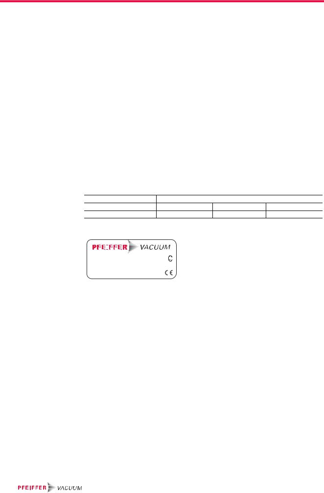
To correctly identify the product when communicating with Pfeiffer Vacuum, always have the information from the rating plate available.
|
|
|
|
|
|
|
|
|
|
|
|
|
|
|
|
D-35614 Asslar |
|
|
|||||||
|
Mod.: HiPace 300 |
Oil: |
--- |
|||||||||
|
|
|
|
DN 100 ISO-K, 3P |
S(N2): |
260 l/s |
||||||
M.-No.: PM P03 900 |
n,f: 60000 1/min, 1000 Hz |
|||||||||||
Ser. -No.: |
Weight: 6.7 kg |
|||||||||||
|
|
|
|
|
|
|
|
|
|
|
Made in Germany |
|
Fig. 1: Example for a rating plate
4.1.3Scope of delivery
●HiPace 300 M with TM 700 and 48 V DC
●Venting valve PM Z01 291
●Protective cover for the high vacuum flange and the fore-vacuum flange
●Operating instructions
10
Product description
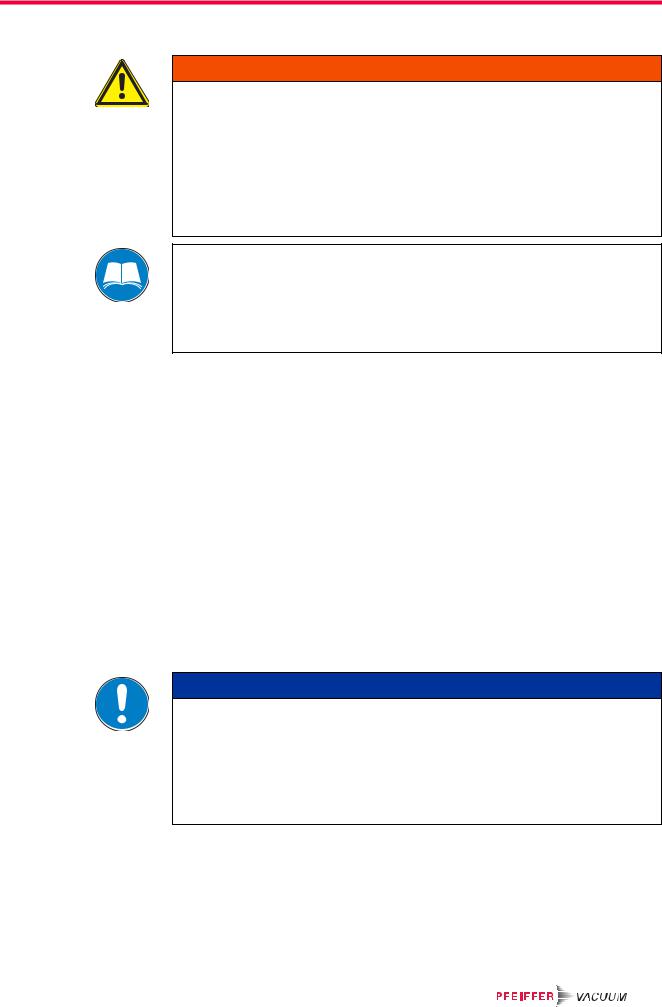
4.2Function
The turbopump HiPace 300 M forms a complete unit together with the electronic drive and magnetic bearing unit TM 700 (in the following just: "electronic drive unit"). For the voltage supply only Pfeiffer Vacuum power supplies may be used (e.g.TPS, OPS or DCU).
4 |
24 |
5
23 |
3 |
83 |
81 |
15.5 |
|
3e |
|
Fig. 2: View of HiPace 300 M with TM 700 |
|
|
|||||
3 |
Pump lower part |
|
5 |
Intermediate piece |
24 |
Venting valve |
|
3e |
Earthing connection |
15.5 |
Cooling water connection |
81 |
Sealing gas connection |
||
4 |
Pump casing |
|
23 |
Electronic drive unit TM 700 |
83 |
Fore-vacuum connection |
|
4.2.1Cooling
●Water cooling
●Convection cooling
●Air cooling (optional)
In the case of excess temperature the electronic drive unit reduces the drive power automatically. Depending on the application and the HiPace different cooling variants are selectable.
4.2.2Rotor bearing
Active-magnetic bearing turbopump
●High vacuum side: electromagnetic radial bearings
●Fore-vacuum side: electromagnetic radial and axial bearings
Active magnetic bearings offer largely wear-free operation and permit lubricant-free vacuum processes. Dry-running safety bearings are installed to avoid contact between the rotor and stator.
4.2.3Drive
Electronic drive unit TM 700
11

Product description
4.3Range of application
The pump HiPace 300 M must be installed and operated under the following ambient conditions:
Installation location |
weather protected (indoors) |
|
Protection category |
IP 54 |
|
Protection class |
III |
|
Ambient temperature |
+5 |
°C to +30 °C with convection cooling without gas throughput |
|
+5 |
°C to +35 °C with air cooling |
|
+5 |
°C to +40 °C with water cooling |
|
|
|
Relative humidity |
max. 80 %, at T 31 °C, up to max. 50 % at T 40 °C |
|
Atmospheric pressure |
750 hPa - 1060 hPa |
|
Installation altitude |
5000 m max. |
|
Degree of pollution |
2 |
|
Permissible surr. magnetic field |
5 mT |
|
Overvoltage category |
II |
|
Connection voltage TM 700 |
48 V DC |
|
Remarks to ambient conditions
The specified permissible ambient temperatures apply to operation of the turbopump at maximum permissible fore-vacuum pressure or at maximum gas throughput depending on the cooling method. The turbopump is intrinsically safe by a redundant temperature monitoring.
●By reducing the fore-vacuum pressure or gas throughput, the turbopump can be operated at higher ambient temperatures.
●If the maximum permissible operating temperature of the turbopump is exceeded, the electronic drive unit reduces drive power first and switches off then, if necessary.
12
Installation
5 Installation
WARNING
Danger to life by the turbopump ripping off in case of malfunctions
Rapid shutdown of the rotor generates destructive torques in case of burst up to 3000 Nm according to ISO 27892. If it is not properly fixed, the turbopump rips off. The energy released thereby can throw the entire pump or pieces from its interior through
the room. There is a danger of severest, possibly fatal, injuries as well as serious property damage.
Carefully follow the installation instructions in this handbook.
Only use approved original parts from Pfeiffer Vacuum (Accessories) for the installation.
Installation and operation of accessories
Pfeiffer Vacuum pumps can be equipped with a series of adapted accessories. The installation, operation and maintenance of connected devices are described in detail in the operating instructions of the individual components.
For information on order numbers of components, see "Accessories".
Use original accessory parts only.
5.1Preparatory work
When installing the pump, observe the following conditions:
●the ambient conditions specified for the range of application
●When using a casing heating and a water cooling unit the temperature of the connected flange of the vacuum chamber must not exceed 120 °C.
●It is not allowed to operate the device in systems where impact-like stresses and vibrations or periodically forces occur.
Ensure sufficient cooling for the turbopump.
Where magnetic fields > 5 mT are involved, a suitable shielding must be used. Check installation location and consult Pfeiffer Vacuum if needed!
The maximum permissible rotor temperature for the turbopump is 110 °C. If high temperatures arise for process reasons, the radiated heat input must not exceed 2.4 W. Install suitable screening sheets, if necessary (design information on request).
5.2Set-up
NOTICE
Danger due to external vibrations
External pump vibrations may cause magnet bearing overload and therefore safety bearing stress.
Avoid lateral and tilting pump movements.
Configure the system appropriately to compensate for external vibration, e.g. due to high-vacuum valves.
Secure the vacuum chamber provided by the customer against moving and tilting.
●Ensure the greatest possible cleanliness when installing any high vacuum parts. Unclean components prolong the pump-down time.
●All flange components must be grease-free, dust-free and dry at installation.
5.2.1Earthquake safety
An earthquake can result in contact with the safety bearings. All forces occuring hereby are safely absorbed by the properly installed flange connections.
13
Loading...