


OPERATING INSTRUCTIONS
EN
Translation of the Original
HICUBE ECO
Turbo pumping stations

Dear Customer,
Thank you for choosing a Pfeiffer Vacuum product. Your new turbo pumping station is designed to support you by its performance, its perfect operation and without interfering your individual application. The name Pfeiffer Vacuum stands for high-quality vacuum technology, a comprehensive and complete range of top-quality products and first-class service. With this expertise, we have acquired a multitude of skills contributing to an efficient and secure implementation of our product.
Knowing that our product must not interfere with your actual work, we are convinced that our product offers you the solution that supports you in the effective and trouble-free execution of your individual application.
Please read these operating instructions before putting your product into operation for the first time. If you have any questions or suggestions, please feel free to contact info@pfeiffervacuum.de.
Further operating instructions from Pfeiffer Vacuum can be found in the Download Center on our website.
Disclaimer of liability
These operating instructions describe all models and variants of your product. Note that your product may not be equipped with all features described in this document. Pfeiffer Vacuum constantly adapts its products to the latest state of the art without prior notice. Please take into account that online operating instructions can deviate from the printed operating instructions supplied with your product.
Furthermore, Pfeiffer Vacuum assumes no responsibility or liability for damage resulting from the use of the product that contradicts its proper use or is explicitly defined as foreseeable misuse.
Copyright
This document is the intellectual property of Pfeiffer Vacuum and all contents of this document are protected by copyright. They may not be copied, altered, reproduced or published without the prior written permission of Pfeiffer Vacuum.
We reserve the right to make changes to the technical data and information in this document.
2/60

Table of contents
Table of contents
1 |
About this manual |
7 |
||
|
1.1 |
Validity |
7 |
|
|
|
1.1.1 |
Applicable documents |
7 |
|
|
1.1.2 |
Variants |
7 |
|
1.2 |
Target group |
7 |
|
|
1.3 |
Conventions |
7 |
|
|
|
1.3.1 Instructions in the text |
7 |
|
|
|
1.3.2 |
Pictographs |
8 |
|
|
1.3.3 Stickers on the product |
8 |
|
|
|
1.3.4 |
Abbreviations |
9 |
2 |
Safety |
10 |
|
|
2.1 |
General safety instructions |
10 |
|
2.2 |
Safety instructions |
10 |
|
2.3 |
Safety precautions |
13 |
|
2.4 |
Limits of use of the product |
13 |
|
2.5 |
Proper use |
14 |
|
2.6 |
Foreseeable improper use |
14 |
3 |
Product description |
15 |
||
|
3.1 |
Identifying the product |
15 |
|
|
3.2 |
Scope of delivery |
16 |
|
|
3.3 |
Function |
16 |
|
|
|
3.3.1 |
Control interface |
16 |
|
|
3.3.2 |
Drive |
17 |
|
|
3.3.3 |
Cooling |
17 |
4 |
Transportation and Storage |
18 |
|
|
4.1 |
Transporting the pumping station |
18 |
|
4.2 |
Transport protection |
18 |
|
4.3 |
Storing the pumping station |
19 |
5 |
Installation |
20 |
|
|
5.1 |
Preparing for set-up |
20 |
|
5.2 |
Setting up the pumping station |
20 |
|
5.3 |
Anchoring pumping station |
20 |
|
5.4 |
Connecting the high vacuum side |
21 |
|
|
5.4.1 Designing the counter flange |
21 |
|
|
5.4.2 Using accessories for the high vacuum connection |
22 |
|
|
5.4.3 Connecting the turbopump externally |
23 |
|
|
5.4.4 Installation of ISO-KF flange |
23 |
|
|
5.4.5 Attaching ISO-K flange onto ISO-K |
24 |
|
|
5.4.6 Installation of ISO-K flange onto ISO-F |
24 |
|
|
5.4.7 Fastening CF flange to CF-F |
26 |
|
5.5 |
Connecting the exhaust side |
27 |
|
5.6 |
Modifying the DCU for remote operation |
28 |
|
5.7 |
Connecting accessories for the pumping station |
29 |
|
5.8 |
Removing transport lock |
29 |
|
5.9 |
Grounding the pumping station |
30 |
|
5.10 |
Establishing the mains connection |
30 |
6 |
Operation |
32 |
|
|
6.1 |
Commissioning |
32 |
|
6.2 |
Switching on the turbo pumping station |
33 |
|
6.3 |
Normal operation |
33 |
|
6.4 |
Operation with gas ballast (applies to MVP 015-2 only) |
33 |
|
6.5 |
Operation monitoring |
35 |
3/60

Table of contents
|
|
6.5.1 |
Operating mode display via LED |
35 |
|
|
6.5.2 |
Temperature monitoring |
35 |
|
6.6 |
Switching off and venting |
35 |
|
|
|
6.6.1 Shutting down the turbo pumping station |
35 |
|
|
|
6.6.2 |
Venting |
36 |
7 |
Maintenance |
37 |
||
|
7.1 |
General maintenance information |
37 |
|
|
7.2 |
Maintenance intervals and responsibilities |
37 |
|
|
7.3 |
Replacing mains fuses |
37 |
|
|
7.4 |
Removing components for maintenance |
38 |
|
|
|
7.4.1 Removing the electrical connections |
39 |
|
|
|
7.4.2 Dismantling the turbopump from the pumping station |
39 |
|
8 |
Decommissioning |
41 |
||
|
8.1 |
Shutting down for longer periods |
41 |
|
|
8.2 |
Recommissioning |
41 |
|
|
8.3 |
Disposing of the vacuum pump |
41 |
|
9 |
Malfunctions |
42 |
||
|
9.1 |
General |
42 |
|
|
9.2 |
Troubleshooting |
42 |
|
|
9.3 |
Error codes |
43 |
|
10 |
Service solutions from Pfeiffer Vacuum |
47 |
||
11 |
Accessories |
49 |
||
12 |
Technical data and dimensions |
50 |
||
|
12.1 |
General |
50 |
|
|
12.2 |
Technical data |
50 |
|
|
12.3 |
Dimensioned drawings |
55 |
|
|
Declaration of Conformity |
58 |
||
4/60

List of tables
List of tables |
|
|
Tbl. 1: |
Stickers on the product............................................................................................... |
8 |
Tbl. 2: |
Abbreviations used in the document.......................................................................... |
9 |
Tbl. 3: |
Limits of use for turbopump stations......................................................................... |
14 |
Tbl. 4: |
Pumping station component combination options.................................................... |
16 |
Tbl. 5: |
Requirements for on-site high vacuum connection.................................................. |
22 |
Tbl. 6: |
Changing pumping speed with splinter shield or protective screen.......................... |
22 |
Tbl. 7: |
Factory setting of key parameters on delivery.......................................................... |
33 |
Tbl. 8: |
Description of the key functions of the DCU............................................................. |
33 |
Tbl. 9: |
LED display and meaning at the DCU...................................................................... |
35 |
Tbl. 10: |
Factory settings for delayed venting of turbopumps................................................. |
36 |
Tbl. 11: |
Preset accessory connections.................................................................................. |
38 |
Tbl. 12: |
Troubleshooting........................................................................................................ |
43 |
Tbl. 13: |
Warning and error messages when using the DCU................................................. |
43 |
Tbl. 14: |
Error and warning messages for turbopump electronic drive unit............................ |
45 |
Tbl. 15: |
Error and warning messages for MVP 015 diaphragm pump electronic drive unit... |
46 |
Tbl. 16: |
Conversion table: Pressure units.............................................................................. |
50 |
Tbl. 17: |
Conversion table: Units for gas throughput.............................................................. |
50 |
Tbl. 18: |
Technical data HiCube 30 Eco, DN 40 ISO-KF........................................................ |
51 |
Tbl. 19: |
Technical data HiCube 30 Eco, DN 63 CF-F............................................................ |
51 |
Tbl. 20: |
Technical data HiCube 30 Eco, DN 63 ISO-K.......................................................... |
52 |
Tbl. 21: |
Technical data HiCube 80 Eco, DN 40 ISO-KF........................................................ |
52 |
Tbl. 22: |
Technical data HiCube 80 Eco, DN 63 CF-F............................................................ |
53 |
Tbl. 23: |
Technical data HiCube 80 Eco, DN 63 ISO-K.......................................................... |
53 |
Tbl. 24: |
Technical data HiCube 300 Eco, DN 100 CF-F........................................................ |
54 |
Tbl. 25: |
Technical data HiCube 300 Eco, DN 100 ISO-K...................................................... |
55 |
5/60

List of figures |
|
|
List of figures |
|
|
Fig. 1: |
Position of the labels on the product.......................................................................... |
9 |
Fig. 2: |
Overview: Turbo and backing pump combinations................................................... |
15 |
Fig. 3: |
Example combinations product overview................................................................. |
16 |
Fig. 4: |
DCU control panel.................................................................................................... |
17 |
Fig. 5: |
Transporting the turbo pumping station manually.................................................... |
18 |
Fig. 6: |
Secure HiCube 300 Eco with lashing straps............................................................ |
21 |
Fig. 7: |
Flange connection ISO-KF to ISO-KF...................................................................... |
23 |
Fig. 8: |
Flange connection ISO-K to ISO-F, bracket screws................................................. |
24 |
Fig. 9: |
Flange connection CF-F, hexagon head screw and through hole............................ |
26 |
Fig. 10: |
Flange connection CF-F, stud screw and tapped hole............................................. |
26 |
Fig. 11: |
Flange connection CF-F, stud screw and through hole............................................ |
27 |
Fig. 12: |
Example backing pump exhaust connection............................................................ |
27 |
Fig. 13: |
Remove DCU from pumping station......................................................................... |
28 |
Fig. 14: |
DCU connection as remote control........................................................................... |
29 |
Fig. 15: |
Backing pump transport lock.................................................................................... |
30 |
Fig. 16: |
Example: Connecting the grounding cable............................................................... |
30 |
Fig. 17: |
Power supply connector and master switch on HiCube Eco.................................... |
31 |
Fig. 18: |
Example: DCU display for second parameter set..................................................... |
34 |
Fig. 19: |
Replace main fuses.................................................................................................. |
38 |
Fig. 20: |
Electrical connections............................................................................................... |
39 |
Fig. 21: |
Dismantling the turbopump....................................................................................... |
39 |
Fig. 22: |
Dimensions of HiCube 30 Eco, DN 40 ISO-KF........................................................ |
55 |
Fig. 23: |
Dimensions of HiCube 30 Eco, DN 63 CF-F............................................................ |
56 |
Fig. 24: |
Dimensions of HiCube 30 Eco, DN 63 ISO-K........................................................... |
56 |
Fig. 25: |
Dimensions of HiCube 80 Eco, DN 40 ISO-KF........................................................ |
56 |
Fig. 26: |
Dimensions of HiCube 80 Eco, DN 63 CF-F............................................................ |
56 |
Fig. 27: |
Dimensions of HiCube 80 Eco, DN 63 ISO-K........................................................... |
57 |
Fig. 28: |
Dimensions of HiCube 300 Eco, DN 100 CF-F........................................................ |
57 |
Fig. 29: |
Dimensions of HiCube 300 Eco, DN 100 ISO-K....................................................... |
57 |
6/60

About this manual
1 About this manual
IMPORTANT
Read carefully before use.
Keep the manual for future consultation.
1.1 Validity
These operating instructions are for customers of Pfeiffer Vacuum. They describe the function of the designated product and provide the most important information for safe usage of the product. The descriptions comply with applicable directives. All information provided in these operating instructions refer to the current development status of the product. The documentation remains valid as long as the customer does not modify the product in any way.
1.1.1 Applicable documents
HiCube Eco |
Operating instructions |
|
|
Declaration of conformity |
A component of these instructions |
|
|
Operating instructions for the individual components |
see product description |
|
|
1.1.2 Variants
This manual applies to HiCube Eco ling turbopump stations:
● HiCube 30 Eco
● HiCube 80 Eco
● HiCube 300 Eco
1.2 Target group
This operating instructions are aimed at all persons performing the following activities on the product:
●transport,
●setup (installation),
●usage and operation,
●decommissioning,
●maintenance and cleaning,
●storage or disposal.
The work described in this document is only permitted to be performed by persons with the appropriate technical qualifications (expert personnel) or who have received the relevant training from Pfeiffer Vacuum.
1.3 Conventions
1.3.1 Instructions in the text
Usage instructions in the document follow a general structure that is complete in itself. The required action is indicated by an individual step or multi-part action steps.
Individual action step
A horizontal, solid triangle indicates the only step in an action. ► This is an individual action step.
Sequence of multi-part action steps
The numerical list indicates an action with multiple necessary steps.
1.Step 1
2.Step 2
3....
7/60
About this manual
1.3.2 Pictographs
Pictographs used in the document indicate useful information.
Note
Tip
1.3.3 Stickers on the product
This section describes all the stickers on the product along with their meaning.
|
|
|
Rating plate |
D-35614 Asslar |
|
The rating plate is located on the back of the pumping station |
|
|
|
||
Mod. |
HiCube 80 Eco |
|
housing. |
P/N |
PM S74 100 00 |
|
|
S/N |
- - - - - - - - |
|
|
Fuse |
T 2 A H 250 VAC |
TÜV Rheinland |
|
Input |
100-240 V +/-10 % 2.00 A 50/60 Hz C |
US |
|
Mass |
12.5 kg |
Made in Germany 2018/06 |
|
|
|
|
|
|
|
|
|
Transport protection |
|
VOR INBETRIEBNAHME |
This sticker indicates that the backing pump transport lock |
||||||||
TRANSPORTSICHERUNG LÖSEN |
|||||||||
must be released prior to commissioning. |
|||||||||
BEFORE USE UNFASTEN THE |
|||||||||
|
|||||||||
TRANSPORT PROTECTION |
|
||||||||
|
|
|
|
|
|
|
|
|
|
|
|
|
|
|
|
warranty seal |
Closure seal |
||
|
|
|
|
|
|
The product is sealed ex-factory. Damaging or removing a clo- |
|||
|
|
|
|
|
|
|
|
||
|
|
|
|
|
|
|
|
sure seal results in loss of the warranty. |
|
|
|
|
|
|
|
|
|
|
|
|
|
|
|
|
|
|
|
Protection class |
|
|
|
|
|
|
|
|
|
||
|
|
|
|
|
|
|
|
The sticker describes protection class 1 for the product. The |
|
|
|
|
|
|
|
|
|
||
|
|
|
|
|
|
|
|
positioning indicates the position for the ground connection. |
|
|
|
|
|
|
|
|
|
||
|
|
|
|
|
|
|
|
|
|
|
|
|
|
|
|
|
|
Electrical voltage warning |
|
|
|
|
|
|
|
|
|
The sticker warns of the risk of electric shock when working |
|
|
|
|
|
|
|
|
|
with the housing open. |
|
|
|
|
|
|
|
|
|
|
|
|
|
|
|
|
|
|
|
Mandatory: disconnect mains plug |
|
|
|
|
|
|
|
|
|
The sticker indicates that the mains plug is to be disconnected |
|
|
|
|
|
|
|
|
|
from the device prior to installation and maintenance work. |
|
Tbl. 1: Stickers on the product
8/60
About this manual
1 |
2,3 |
4 |
5
6
7
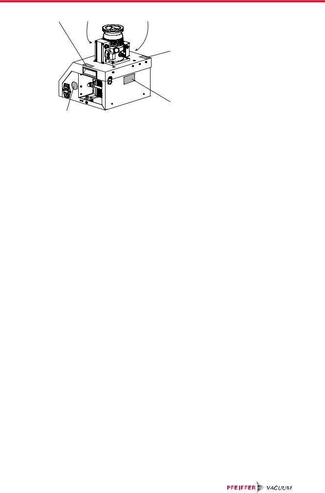
Fig. 1: |
Position of the labels on the product |
|
|
|
1 |
Transport lock sticker |
5 |
Transport lock sticker |
|
2 |
Closure seal (vacuum pump) |
6 |
Rating plate |
|
3 |
Ground connection sticker (vacuum pump) |
7 |
Mandatory disconnect mains plug sign |
|
4Electrical voltage (power supply pack) warning sign
1.3.4 Abbreviations
Abbreviation |
Meaning in the document |
|
|
|
|
CF |
|
flange: Metal-sealed connector conforming to ISO 3669 |
|
|
|
d |
|
Measurement of the diameter (in mm) |
|
|
|
DCU |
|
Display Control Unit (display and control unit from Pfeiffer Vacuum). |
|
|
|
DN |
|
Nominal diameter as size description |
|
|
|
f |
|
Measurement of the rotation speed of a vacuum pump (frequency, in rpm or Hz) |
|
|
|
HV |
|
High vacuum flange, high vacuum side |
|
|
|
ISO |
|
flange: Connector conforming to ISO 1609 and ISO 2861 |
|
|
|
LC |
|
Display: Liquid crystal display (LCD) |
|
|
|
LED |
|
Light-emitting diode |
|
|
|
MVP |
|
Diaphragm vacuum pump |
|
|
|
PE |
|
Earthed conductor (protective earth) |
|
|
|
[P:xxx] |
|
Control parameters of the electronic drive unit. Printed in bold as a three-digit num- |
|
|
ber in square brackets. Frequently displayed in combination with a short designation. |
|
|
Example: [P:312] Software version |
|
|
|
T |
|
Temperature (in °C) |
|
|
|
TC |
|
Turbopump electronic drive unit (turbo controller) |
|
|
|
TPS |
|
Power supply (turbo power supply) |
|
|
|
X3 |
|
15-pole D-Sub connecting socket on the electronic drive unit of the turbopump |
|
|
|
Tbl. 2: |
Abbreviations used in the document |
|
9/60

Safety
2 Safety
2.1 General safety instructions
This document includes the following four risk levels and one information level.
 DANGER
Imminent danger
Indicates a hazardous situation which, if not avoided, will result in death or serious injury. ► Instructions on avoiding the hazardous situation
 WARNING
Possibly imminent danger
Indicates a hazardous situation which, if not avoided, could result in death or serious injury. ► Instructions on avoiding the hazardous situation
 CAUTION
Possibly imminent danger
Indicates a hazardous situation which, if not avoided, could result in minor or moderate injury. ► Instructions on avoiding the hazardous situation
NOTICE
Danger of property damage
Notice is used to address practices not related to physical injury. ► Instructions on avoiding property damage
Notes, tips or examples indicate important information on the product or on this document.
2.2 Safety instructions
All safety instructions in this document are based on the results of the risk assessment carried out in accordance with Machinery Directive 2006/42/EC Annex I and EN ISO 12100 Section 5. Where applicable, all life cycle phases of the product were taken into account.
Risks during transport
 WARNING
Danger of serious injury due to falling objects
Due to falling objects there is a risk of injuries to limbs through to broken bones.
►Take particular care and pay special attention when transporting products manually.
►Do not stack the products.
►Wear protective equipment, e.g. safety shoes.
Risks during installation
 WARNING
Danger to life from electric shock in the event of a fault
In the event of a fault, devices connected to the mains may be live. There is a danger to life from electric shock when making contact with live components.
► Always keep the mains connection freely accessible so you can disconnect it at any time.
10/60
Safety
 WARNING
Danger to life from electric shock due to improperly performed installation
The device uses voltage that is dangerous on contact as the electrical power supply. Potentially fatal situations arise due to unsafe or incorrectly installation when reaching into the device.
►Ensure that the system is safely integrated into an emergency off safety circuit.
►Do not carry out any unauthorized modifications or changes to the device.
 WARNING
Risk of cuts on moving, sharp-edged parts when reaching into the open high vacuum flange
With the high vacuum flange open, access to sharp-edged parts is possible. A manual rotation of the rotor increases the danger situation. There is the risk of cuts, up to the separation of body parts (e.g. fingertips). There is a risk of hair and loose clothing being drawn in. Objects falling in destroy the turbopump during subsequent operation.
►Only remove the original protective covers immediately prior to connecting the high vacuum flange.
►Do not reach into the high vacuum connection.
►Wear protective gloves during installation.
►Do not start the turbopump with open vacuum connections.
►Always carry out the mechanical installation before electrical connection.
►Prevent access to the high vacuum connection of the turbopump from the operator side (e.g. open vacuum chamber).
 WARNING
Risk of injury caused by the turbopump breaking away with the vibration compensator in the event of a malfunction
Sudden jamming of the rotor generates high destructive torques in accordance with ISO 27892. When using a vibration compensator, this will probably lead to the turbopump being sheared off in use. The energy that this would release could throw the entire turbopump or shattered pieces from its interior through the surrounding space. Potentially dangerous gases can escape. There is a risk of very serious injuries, including death, and extensive property damage.
►Take suitable safety precautions on-site for the compensation of the occurring torques.
►Before installing a vibration compensator, you must first of all contact Pfeiffer Vacuum.
 CAUTION
Risk of injury from bursting due to high pressure in the exhaust line
Faulty or insufficient exhaust lines cause hazardous situations, e.g. increase in exhaust pressure. There is a risk of bursting. It is not possible to rule out the risk of injuries due to broken pieces flying around, high escaping pressure and damage to the equipment.
►Lay the exhaust line without shut-off units.
►Observe the permissible pressures and pressure differentials of the product.
►Check the exhaust line regularly for correct function.
Risks during operation
 WARNING
Danger of death from poisoning due to toxic gases being expelled without an exhaust line
Exhaust gases and vapors are released from the turbo pumping station unhindered during normal usage. In the case of processes with toxic media, there is a risk of injury and danger of death due to poisoning.
►Note the corresponding regulations for handling toxic substances.
►Toxic process gases should be safely conveyed away via an exhaust line.
11/60
Safety
 CAUTION
Risk of injury from bursting due to high pressure in the exhaust line
Faulty or insufficient exhaust lines cause hazardous situations, e.g. increase in exhaust pressure. There is a risk of bursting. It is not possible to rule out the risk of injuries due to broken pieces flying around, high escaping pressure and damage to the equipment.
►Lay the exhaust line without shut-off units.
►Observe the permissible pressures and pressure differentials of the product.
►Check the exhaust line regularly for correct function.
Risks during maintenance
 WARNING
Danger to life from electric shock during maintenance and service work
The device is only completely de-energized when the mains plug has been disconnected and the turbopump is at a standstill. There is a danger to life from electric shock when making contact with live components.
►Before performing all work, switch off the main switch.
►Wait until the turbopump comes to a standstill (rotation speed =0).
►Remove the mains plug from the device.
►Secure the device against unintentional restarting.
 WARNING
Health hazard through poisoning from toxic contaminated components or devices
Toxic process media result in contamination of devices or parts of them. During maintenance work, there is a risk to health from contact with these poisonous substances. Illegal disposal of toxic substances causes environmental damage.
►Take suitable safety precautions and prevent health hazards or environmental pollution by toxic process media.
►Decontaminate affected parts before carrying out maintenance work.
►Wear protective equipment.
Risks during disposal
 WARNING
Health hazard through poisoning from toxic contaminated components or devices
Toxic process media result in contamination of devices or parts of them. During maintenance work, there is a risk to health from contact with these poisonous substances. Illegal disposal of toxic substances causes environmental damage.
►Take suitable safety precautions and prevent health hazards or environmental pollution by toxic process media.
►Decontaminate affected parts before carrying out maintenance work.
►Wear protective equipment.
Risks in the event of malfunctions
 WARNING
Danger to life from the turbopump breaking away in the event of a fault
Sudden blocking of the rotor generates high destructive torques in accordance with ISO 27892. If the turbopump is not properly secured, it will tear off. The energy released in this way can propel the entire turbopump or shattered pieces from its interior through the surrounding area. Potentially dangerous gases may escape. There is a risk of serious injury, potentially even fatal, and significant equipment damage.
►Follow the installation instructions for this turbopump.
►Observe the requirements regarding stability and design of the counter flange.
►Use only original accessories or fixing material approved by Pfeiffer Vacuum for the installation.
12/60

Safety
 WARNING
Risk of injury caused by the turbopump breaking away with the vibration compensator in the event of a malfunction
Sudden jamming of the rotor generates high destructive torques in accordance with ISO 27892. When using a vibration compensator, this will probably lead to the turbopump being sheared off in use. The energy that this would release could throw the entire turbopump or shattered pieces from its interior through the surrounding space. Potentially dangerous gases can escape. There is a risk of very serious injuries, including death, and extensive property damage.
►Take suitable safety precautions on-site for the compensation of the occurring torques.
►Before installing a vibration compensator, you must first of all contact Pfeiffer Vacuum.
2.3 Safety precautions
Duty to provide information on potential dangers
The product holder or user is obliged to make all operating personnel aware of dangers posed by this product.
Every person who is involved in the installation, operation or maintenance of the product must read, understand, and adhere to the safety-related parts of this document.
Infringement of conformity due to modifications to the product
The Declaration of Conformity from the manufacturer is no longer valid if the operator changes the original product or installs additional equipment.
●Following installation into a system, the operator is required to check and reevaluate as necessary the conformity of the overall system in the context of the relevant european Directives before commissioning that system.
General safety precautions when handling the product
►Observe all applicable safety and accident prevention regulations.
►Check that all safety measures are observed at regular intervals.
►Do not expose body parts to the vacuum.
►Always ensure a secure connection to the earthed conductor (PE).
►Never disconnect plug connections during operation.
►Observe the above shutdown procedures.
►Before working on the high vacuum connection, wait until the rotor has stopped completely (rotation speed f = 0).
►Never put the device into operation with the high vacuum connection open.
►Keep lines and cables away from hot surfaces (> 70°C).
►Never fill or operate the unit with cleaning agents or cleaning agent residues.
►Do not carry out your own conversions or modifications on the unit.
►Observe the unit protection class prior to installation or operation in other environments.
2.4 Limits of use of the product
Parameter |
Limit value |
|
|
Installation location |
weatherproof (internal space) |
|
|
Air pressure |
750 hPa to 1060 hPa |
|
|
Installation altitude |
max. 2000 m |
|
|
Rel. air humidity |
max. 80%, at T < 31 °C |
|
up to max. 50% at T < 40 °C |
|
|
Protection class |
I |
|
|
Excess voltage category |
II |
|
|
Permissible protection class |
IP20 |
|
|
13/60
Safety
Parameter |
Limit value |
|
|
|
|
Degree of contamination |
2 |
|
|
|
|
Ambient temperature |
5°C to 35°C with air cooling |
|
|
|
5°C to 40°C with water cooling |
|
|
|
Permissible surrounding magnetic field |
depending on turbopump used |
|
|
|
|
Maximum irradiated thermal output |
depending on turbopump used |
|
|
|
|
Maximum permissible rotor temperature of the turbopump |
90 °C |
|
|
|
|
Tbl. 3: |
Limits of use for turbopump stations |
|
Notes on ambient conditions
The specified permissible ambient temperatures apply to operation of the turbopump at maximum permissible backing pressure or at maximum gas throughput, depending on the cooling type. The turbopump is intrinsically safe thanks to redundant temperature monitoring.
●The reduction in backing pressure or gas throughput permits operation of the turbopump at higher ambient temperatures as well.
●If the maximum permissible operating temperature of the turbopump is exceeded, the electronic drive unit first reduces the drive output and switches it off where necessary.
2.5 Proper use
●The turbo pumping station is only used to generate the vacuum.
●The turbo pumping station is only used to extract dry and inert gases.
●The turbo pumping station is only intended for use in enclosed interior spaces.
●The turbo pumping station is intended for use as a table-top unit.
2.6 Foreseeable improper use
Improper use of the product invalidates all warranty and liability claims. Any use that is counter to the purpose of the product, whether intentional or unintentional, is regarded as misuse, in particular:
●Establishing the voltage supply without correct installation
●Installation with non-specified fastening material
●Pumping explosive media
●Pumping of corrosive media
●Pumping of condensing vapors
●Pumping of fluids
●Pumping of dust
●Operation with impermissible high gas throughput
●Operation with impermissible high fore-vacuum pressure
●Operation with excessively high irradiated heat output
●Operation in impermissible high magnetic fields
●Operation in an incorrect gas mode
●Venting with impermissible high venting rates
●Use for pressure generation
●Use in areas with ionizing radiation
●Operation in explosion-hazard areas
●Use in systems in which sporadic loads and vibrations or periodic forces act on the device
●The causing of hazardous operating conditions by a presetting on the electronic drive unit that is contrary to the process
●Use of accessories or spare parts that are not listed in these instructions
14/60
Product description
3 Product description
3.1 Identifying the product
►To ensure clear identification of the product when communicating with Pfeiffer Vacuum, always keep all of the information on the rating plate to hand.
►Learn about certifications through test seals on the product or at www.tuvdotcom.com with company ID no. 000021320.
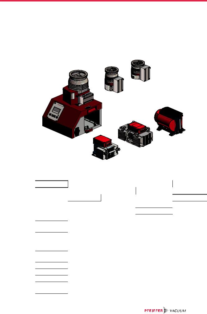
HIPACE 300 HIPACE 80 |
HIPACE 30 |
|
|
MVP 015-2 |
MVP 015-4 |
MVP 030-3 |
||
Fig. 2: |
Overview: Turbo and backing pump combinations |
|
|
|||
Feature |
|
|
HiCube Eco |
|
|
Operating in- |
HV flange size |
DN 40/DN 63 |
DN 100 |
|
structions |
||
|
|
|||||
|
|
HiPace 30 |
|
|
|
PT 0510 BN |
Turbopump |
|
HiPace 80 |
|
|
PT 0208 BN |
|
|
|
HiPace 300 |
|
PT 0202 BN |
||
|
|
|
|
|
||
|
|
|
|
HiPace 300 H |
|
PT 0509 BN |
Electronic drive |
TC 110 |
TC 110 |
TC 110 |
|
PT 0204 BN |
|
unit |
|
|
|
|
|
|
Diaphragm |
MVP 015 2 |
MVP 015 2 |
(MVP 015 2) |
|
PU 0070 BN |
|
Pump |
|
MVP 015 4 |
MVP 015 4 |
MVP 015 4 |
|
PU 0070 BN |
|
|
MVP 030 3 |
MVP 030 3 |
MVP 030 3 |
|
PU 0065 BN |
Current supply |
TPS onboard, |
TPS onboard, |
TPS onboard, |
|
|
|
|
|
24 V DC |
24 V DC |
24 V DC |
|
|
Control unit |
DCU 002 |
DCU 002 |
DCU 002 |
|
PT 0250 BN |
|
Air cooling |
|
yes |
yes |
yes |
|
PT 0500 BN |
Venting valve |
optional |
optional |
optional |
|
PT 0228 BN |
|
Housing heater |
not available |
Optional, with CF |
Optional, with CF |
PT 0233 BN |
||
1) |
|
|
flange only |
flange only |
|
|
1)Water cooling required
15/60

Product description
Tbl. 4: Pumping station component combination options
3.2 Scope of delivery
●HiCube Eco turbo pumping station
●Protective cover for the high vacuum flange
●Extension cable M12 on M12, 3 m
●Power supply cable, country-specific
●Operating instructions for the turbo pumping station and individual components
3.3 Function
Turbo pumping stations are fully automatic pump units ready for connection. A turbo pumping station consists of a portable or mobile vacuum pump unit, with a turbopump and a specially matched backing pump.
15 |
1 |
2 |
14 |
|
3 |
|
|
|
|
|
4 |
13 |
|
5 |
|
|
|
12 |
|
|
11 |
|
6 |
|
|
10 |
9 |
|
8 |
7 |
Fig. 3: |
Example combinations product overview |
|
|
|||
1 |
Housing |
|
9 |
DCU 002 display and control unit |
||
2 |
HiPace 80 turbopump, DN 63 ISO-K |
10 |
Attachment hooks (HiCube 300 Eco only) |
|||
3 |
Electronic drive unit TC 110 |
|
11 |
Transport protection |
|
|
4 |
Connection cable |
|
12 |
MVP 030-3 diaphragm pump backing pump |
||
5 |
Ground terminal |
|
13 |
Recessed handle |
|
|
6 |
MVP 015-2 diaphragm pump backing pump |
14 |
HiPace 300 turbopump, DN 100 CF-F |
|||
7 |
Master switch |
|
15 |
Air cooling |
|
|
8Mains supply plug
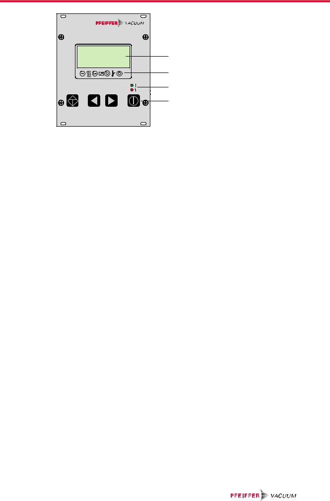
3.3.1 Control interface
The integrated DCU 002 display and control unit serves to control and monitor the turbo pumping station. The DCU is optionally used as a remote control when removing the housing and using an extension cable.
16/60
Product description
DCU |
1 |
2 |
3 |
4 |
Fig. 4: DCU control panel
1 |
LC display, illuminated |
3 |
LED operating display |
2 |
Status icons |
4 |
Control keys |
3.3.2 Drive
●Electronic drive unit of the turbopump
●Electronic drive unit of the backing pump
3.3.3 Cooling
●Air cooling
●Water cooling (optional)
At excessively high temperatures, the electronic drive unit automatically reduces the drive power.
17/60
Transportation and Storage
4 Transportation and Storage
4.1 Transporting the pumping station
 WARNING
Danger of serious injury due to falling objects
Due to falling objects there is a risk of injuries to limbs through to broken bones.
►Take particular care and pay special attention when transporting products manually.
►Do not stack the products.
►Wear protective equipment, e.g. safety shoes.
Packing
We recommend keeping the transport packaging and original protective cover.
Instructions for safe transport
►Observe the weight specified on packaging.
–Use a transport aid if necessary (trolley, lift truck).
►Transport the product in its original packaging.
►Always move the product upright, and over the flattest possible surface.
►Always place the product on an adequately sized, level surface.
1
 2
2
3
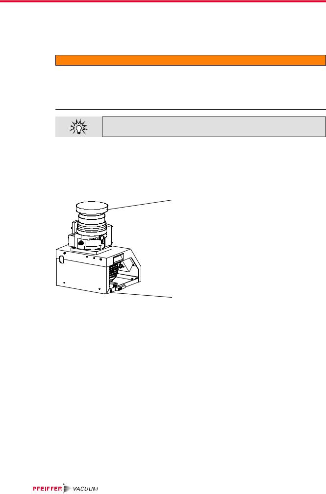
Fig. 5: Transporting the turbo pumping station manually
1 Protective cover |
3 Footprint |
2Recessed handle
Instructions for safe transport without packaging
For transport without packaging, HiCube Eco turbo pumping stations are equipped with recessed handles on the side of the housing frame.
1.Observe weight specified on the rating plate.
2.Lift the turbo pumping station with your hands on the two recessed handles.
3.Always transport the turbo pumping station upright, with its standing surface downwards.
4.Always place turbo pumping station securely on an adequately sized, level surface.
4.2 Transport protection
Backing pumps in HiCube line turbo pumping stations are secured against damage during transport.
Handling the transport lock
1.Release the bucking pump transport lock, only directly prior to commissioning at the installation location.
2.Observe the installation instructions (see chapter “Removing transport lock”, page 29).
18/60
 Loading...