


 Loading...
Translation of the original instructions
 HiPace 2300
Turbopump
Operating Instructions
PT 0243 BEN/E (1207)
EN

Table of contents
Table of contents
1 About this manual . . . . . . . . . . . . . . . . . . . . . . . . . . . . . . . . . . . . . . . . . . . . . . . 3
1.1 Validity. . . . . . . . . . . . . . . . . . . . . . . . . . . . . . . . . . . . . . . . . . . . . . . . . . . . . 3 1.2 Conventions . . . . . . . . . . . . . . . . . . . . . . . . . . . . . . . . . . . . . . . . . . . . . . . . 3
2 Safety . . . . . . . . . . . . . . . . . . . . . . . . . . . . . . . . . . . . . . . . . . . . . . . . . . . . . . . . . 5
2.1 Safety precautions . . . . . . . . . . . . . . . . . . . . . . . . . . . . . . . . . . . . . . . . . . . 5 2.2 Protective equipment . . . . . . . . . . . . . . . . . . . . . . . . . . . . . . . . . . . . . . . . . 6 2.3 Proper use . . . . . . . . . . . . . . . . . . . . . . . . . . . . . . . . . . . . . . . . . . . . . . . . . 6 2.4 Improper use. . . . . . . . . . . . . . . . . . . . . . . . . . . . . . . . . . . . . . . . . . . . . . . . 7
3 Transport and storage. . . . . . . . . . . . . . . . . . . . . . . . . . . . . . . . . . . . . . . . . . . . 8
3.1 Transport. . . . . . . . . . . . . . . . . . . . . . . . . . . . . . . . . . . . . . . . . . . . . . . . . . . 8 3.2 Storage . . . . . . . . . . . . . . . . . . . . . . . . . . . . . . . . . . . . . . . . . . . . . . . . . . . . 8
4 Product description. . . . . . . . . . . . . . . . . . . . . . . . . . . . . . . . . . . . . . . . . . . . . . 9
4.1 Product identification. . . . . . . . . . . . . . . . . . . . . . . . . . . . . . . . . . . . . . . . . . 9 4.2 Function . . . . . . . . . . . . . . . . . . . . . . . . . . . . . . . . . . . . . . . . . . . . . . . . . . 10 4.3 Range of application . . . . . . . . . . . . . . . . . . . . . . . . . . . . . . . . . . . . . . . . . .11
5 Installation . . . . . . . . . . . . . . . . . . . . . . . . . . . . . . . . . . . . . . . . . . . . . . . . . . . . 12
5.1 Set-up . . . . . . . . . . . . . . . . . . . . . . . . . . . . . . . . . . . . . . . . . . . . . . . . . . . . 12 5.2 Preparatory work. . . . . . . . . . . . . . . . . . . . . . . . . . . . . . . . . . . . . . . . . . . . 12 5.3 Assembly . . . . . . . . . . . . . . . . . . . . . . . . . . . . . . . . . . . . . . . . . . . . . . . . . 12 5.4 Filling up the operating fluid . . . . . . . . . . . . . . . . . . . . . . . . . . . . . . . . . . . 16 5.5 Connections to the turbopump . . . . . . . . . . . . . . . . . . . . . . . . . . . . . . . . . 18
6 Operation . . . . . . . . . . . . . . . . . . . . . . . . . . . . . . . . . . . . . . . . . . . . . . . . . . . . . 24
6.1 Commissioning . . . . . . . . . . . . . . . . . . . . . . . . . . . . . . . . . . . . . . . . . . . . . 24 6.2 Operation modes . . . . . . . . . . . . . . . . . . . . . . . . . . . . . . . . . . . . . . . . . . . 25 6.3 Function description . . . . . . . . . . . . . . . . . . . . . . . . . . . . . . . . . . . . . . . . . 25 6.4 Monitoring of the operation conditions . . . . . . . . . . . . . . . . . . . . . . . . . . . 26 6.5 Switching off and venting . . . . . . . . . . . . . . . . . . . . . . . . . . . . . . . . . . . . . 26
7 Maintenance / replacement. . . . . . . . . . . . . . . . . . . . . . . . . . . . . . . . . . . . . . . 27
7.1 Maintenance intervals and responsibilities . . . . . . . . . . . . . . . . . . . . . . . . 27 7.2 Changing the operating fluid . . . . . . . . . . . . . . . . . . . . . . . . . . . . . . . . . . . 28 7.3 Replacing the electronic drive unit . . . . . . . . . . . . . . . . . . . . . . . . . . . . . . 29
8 Decommissioning . . . . . . . . . . . . . . . . . . . . . . . . . . . . . . . . . . . . . . . . . . . . . . 32
8.1 Shutting down for longer periods . . . . . . . . . . . . . . . . . . . . . . . . . . . . . . . 32 8.2 Re-starting . . . . . . . . . . . . . . . . . . . . . . . . . . . . . . . . . . . . . . . . . . . . . . . . 32 8.3 Disposal . . . . . . . . . . . . . . . . . . . . . . . . . . . . . . . . . . . . . . . . . . . . . . . . . . 32
9 Malfunctions . . . . . . . . . . . . . . . . . . . . . . . . . . . . . . . . . . . . . . . . . . . . . . . . . . 33
9.1 Rectifying malfunctions . . . . . . . . . . . . . . . . . . . . . . . . . . . . . . . . . . . . . . . 33
10 Service . . . . . . . . . . . . . . . . . . . . . . . . . . . . . . . . . . . . . . . . . . . . . . . . . . . . . . . 34 11 Spare parts HiPace 2300 . . . . . . . . . . . . . . . . . . . . . . . . . . . . . . . . . . . . . . . . . 35 12 Accessories . . . . . . . . . . . . . . . . . . . . . . . . . . . . . . . . . . . . . . . . . . . . . . . . . . . 36 13 Technical data and dimensions . . . . . . . . . . . . . . . . . . . . . . . . . . . . . . . . . . . 37
13.1 General . . . . . . . . . . . . . . . . . . . . . . . . . . . . . . . . . . . . . . . . . . . . . . . . . . . 37 13.2 HiPace 2300 / HiPace 2300 U . . . . . . . . . . . . . . . . . . . . . . . . . . . . . . . . . 37 13.3 HiPace 2300 C / HiPace 2300 U C . . . . . . . . . . . . . . . . . . . . . . . . . . . . . . 38 13.4 Dimensions . . . . . . . . . . . . . . . . . . . . . . . . . . . . . . . . . . . . . . . . . . . . . . . . 39
Declaration of conformity . . . . . . . . . . . . . . . . . . . . . . . . . . . . . . . . . . . . . . . . 40
2

About this manual
1 About this manual
1.1 Validity
Applicable documents
This operating manual is for customers of Pfeiffer Vacuum. It describes the functioning of the designated product and provides the most important information for safe use of the unit. The description follows applicable EU guidelines. All information provided in this operating manual refer to the current state of the product's development. The documentation remains valid as long as the customer does not make any changes to the product.
Up-to-date operating instructions can also be downloaded from www.pfeiffer-vacu- um.com.
HiPace 2300 |
Operating instructions |
Operating instructions "Electronic drive unit TC 1200" |
PT 0239 BN* |
Declaration of conformity |
Part of this document |
*also available via www.pfeiffer-vacuum.com |
|
1.2 Conventions
Safety instructions The safety instructions in Pfeiffer Vacuum operating instructions are the result of risk evaluations and hazard analyses and are oriented on international certification standards as specified by UL, CSA, ANSI Z-535, SEMI S1, ISO 3864 and DIN 4844. In this document, the following hazard levels and information are considered:
DANGER
Imminent danger
Indicates an imminent hazardous situation that will result in death or serious injury.
WARNING
Possibly imminent danger
Indicates an imminent hazardous situation that can result in death or serious injury.
CAUTION
Possibly imminent danger
Indicates an imminent hazardous situation that can result in minor or moderate injury.
NOTICE
Command or note
Command to perform an action or information about properties, the disregarding of which may result in damage to the product.
3

About this manual
Pictograph definitions
Instructions in the text
Abbreviations used
Symbols used
4
Prohibition of an action or activity in connection with a source of danger, the disregarding of which may result in serious accidents
Warning of a displayed source of danger in connection with operation of the unit or equipment
Command to perform an action or task associated with a source of danger, the disregarding of which may result in serious accidents
Important information about the product or this document
Work instruction: here you have to do something.
DCU: Display and control unit
HPU: Handheld programming unit
TC: Electronic drive unit for turbopump
PB: Profibus version
DN: DeviceNet version
The following symbols are used consistently throughout the diagrams: H High vacuum flange
Fore-vacuum flange
Electric connection
 Cooling water connection F Venting connection
SG Sealing gas connection
Safety
2 Safety
2.1 Safety precautions
Duty to inform
Each person involved in the installation, operation or maintenance of the vacuum pump must read and observe the safety-related parts of these operating instructions.
The operator is obligated to make operating personnel aware of dangers originating from the vacuum pump, the pumped medium and the entire system.
Installation and operation of accessories
Pfeiffer Vacuum pumps can be equipped with a series of adapted accessories. The installation, operation and maintenance of connected devices are described in detail in the operating instructions of the individual components.
For information on order numbers of components, see "Accessories".
Use original accessory parts only.
NOTICE
Checking the safety system against excess rotation speed
To provide the functioning of the integrated safety system for avoiding excess rotation speed, the pump must run-up from the standstill at least once a year.
Switch off the pump and await the complete standstill (rotation speed = 0 Hz).
Run-up the pump according to this operating instructions.
WARNING
Danger of unsafe electrical installation
Safe operation after installation is the responsibility of the operator.
Do not independently modify or change the pump and electrical equipment.
Make sure that the system is integrated in an emergency off safety circuit.
Consult Pfeiffer Vacuum for special requirements.
WARNING
Danger due to lack of power disconnection device as defined in SEMI-S2
Pump and electronic drive unit are not equipped with a power disconnection device. Installation of a user-supplied power disconnection device in accordance with SEMI-S2.
Fit a circuit breaker with an interruption rating of min. 10,000 A.
WARNING
Danger of electric shock
In case of defect, the parts connected to the mains supply are under voltage.
Always keep the mains connection freely accessible so you can disconnect it at any time.
●Do not expose any body parts to the vacuum.
●Observe all safety and accident prevention regulations.
●Regularly check the proper observance off all safety measures.
●Always ensure a safe connection to the protective earthing conductor (PE, protection class I).
●Do not loosen any plug connection during operations.
●Wait for the rotor to reach standstill before peforming work on the high vacuum flange.
●Keep leads and cables well away from hot surfaces (> 70 °C).
●Never fill or operate turbopump with cleaning agent.
●Do not operate the turbopump with open high vacuum flange.
5

Safety
●Do not carry out any unauthorized modifications or conversions to the pump.
●When returning the turbopump observe the shipping instructions.
2.2Protective equipment
kg
Determined situations concerning the handling of vacuum pumps require wearing of personal protective equipment. The owner, respectively the employer are obligated to provide adequate equipment to any operating persons.
DANGER
Danger to health by hazardous substances during maintenance or installation
Depending on the process vacuum pumps, components or operating fluids can be contaminated by toxic, reactive or radioactive substances.
Wear adequate protective equipment during maintenance and repairs or in case of reinstallation.
WARNING
Risk of injury through falling objects
When transporting vacuum pumps by hand, there is a danger through loads slipping and falling down.
Carry small and mid-size vacuum pumps two-handed.
Carry vacuum pumps > 20 kg by a suitable lifting device.
Wear safety shoes with steel toe cap according to directive EN 347.
CAUTION
Risk of injury through hot surfaces
Vacuum pumps can become hot during operation.
Allow the pump to cool before maintenance and repairs.
If necessary wear protective gloves according to directive EN 420.
CAUTION
Risk of injury through sharp edges
Rotor and stator disks of turbopumps have very sharp edges.
Before any working wait for the complete standstill of the pump.
Do not reach in the high vacuum flange.
If necessary wear protective gloves according directive EN 420.
2.3 Proper use
NOTICE
CE conformity
The manufacturer's declaration of conformity becomes invalid if the operator modifies the original product or installs additional components.
Following installation into a plant and before commissioning, the operator must check the entire system for compliance with the valid EU directives and reassess it accordingly.
●The vacuum pump may only be used to generate a vacuum.
●Only operate the turbopump with an approved backing pump.
6

Safety
2.4 Improper use
|
|
Improper use will cause all claims for liability and warranties to be forfeited. Improper use |
|
|
is defined as usage for purposes deviating from those mentioned above, especially: |
|
|
● transport, installation or operation of the pump in invalid orientation |
|
|
● pumping of corrosive gases (exception: pumps in C version) |
|
|
● pumping of corrosive gases without sealing gas (only pumps in C version) |
|
|
● pumping of explosive media |
|
|
● pumping of condensing vapors |
|
|
● operation with improper high gas throughput |
|
|
● operation with improper high fore-vacuum pressures |
|
|
● operation with improper gas mode. |
|
|
● operation with improper high levels of insulated heat input |
|
|
● venting with improper high venting rates |
|
|
● operation of the devices in areas with ionizing radiation |
|
|
● operation in potentially explosive areas |
|
|
● operation of the devices in systems where the turbopumps are subjected to impact- |
|
|
like stress and vibrations or the effect of periodically occurring forces |
|
|
● use of accessories or spare parts, which are not named in this manual |
|
|
● fixing the pump at its bottom part |
|
|
|
|
warranty seal |
Closure seal |
|
|
The product is sealed at the factory. Damaging or removal of a closure seal leads to the |
|
|
loss of liability and warranty entitlements. |
|
|
|
|
|
Do not open the product within its warranty period! |
|
|
For process-related shorter maintenance intervals please contact the Pfeiffer Vacu- |
|
|
um Service. |
|
|
|
7
Transport and storage
3 Transport and storage
3.1 Transport
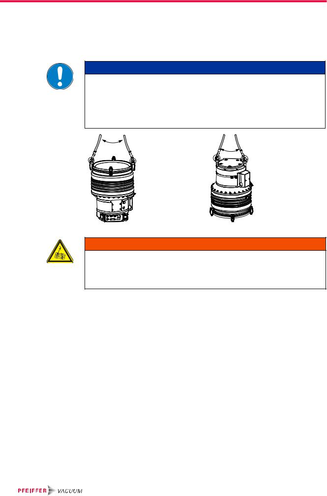
Two pieces of eye bolts are srewed with the pump on delivery.
NOTICE
Observe type-specific mounting orientations!
Incorrect mounting orientations result in contamination of the process vacuum or damage to the pump.
Pay attention to the properties after the model designation on the name plate!
Observe the pictographs on the pump housing!
Do not transport or tilt the pump filled with operating fluid!
60° |
60° |
max |
|
|
max |
Fig. 1: Transport of HiPace 2300 |
Fig. 2: Transport of HiPace 2300 U |
WARNING
Danger from falling and swinging loads!
When lifting the pump there is a danger of falling parts.
Make sure that there are no persons under the suspended load.
Close off and supervise the area under the pump.
Only transport the turbopump in the valid orientation and with vertical rotor axis.
Fix a suitable lifting device on both eye bolts.
–Observe the approved fixing (e.g. maximum opening angle towards the longitudinal axis of the pump).
–Do not lift any additional weights (e.g. vacuum chamber).
Lift the pump perpendicularly out of the packing.
Reuse the transport container. Vacuum pumps should be transported or shipped in the original packing only.
Only remove the protective covers from the high vacuum and the fore-vacuum side immediately before connection.
Keep the original protective covers.
After the transport the eye bolts can be removed.
3.2 Storage
Close the flange openings by using the original protective covers.
Close further connection ports by using the corresponding protective covers.
Store the pump only indoors at temperatures between -25 °C and +55 °C.
In rooms with moist or aggressive atmospheres, the pump must be airproof shrinkwrapped in a plastic bag together with a bag of desiccant.
8

Product description
4 Product description
4.1 Product identification
Variants |
The product designation consists of a family designation (1), the size (2), which is orient- |
||
|
ed on the pumping speed, and if applicable the additional properties (3) of the pump. |
||
HiPace(1) 2300(2)U C(3) |
|
|
|
|
1. Family designation |
2. Model designation |
3. Property designation |
|
HiPace |
2300 = Model designation of |
none = Standard version |
|
|
the pump related to its pump- |
U = Upside-down installation orientation |
|
|
ing speed class |
C = Corrosive gas version |
|
|
|
|
|
|
|
P = Process |
|
|
|
M = Active magnetic bearing |
|
|
|
T = Temperature management system |
●HiPace 2300
●HiPace 2300 C, corrosive gas version
●HiPace 2300 U, for upside-down installation orientation
●HiPace 2300 U C, for upside-down installation orientation and corrosive gases
Pump features
This product has been tested to the requirements of CAN/CSA-C22.2 No. 61010-1, second edition, including Amendment 1, or a later version of the same standard incorporating the same level of testing requirements.
For information about other certifications, if applicable, please see the signet on the product or:
●www.tuvdotcom.com
●TUVdotCOM-ID 0000021320
Characteristics |
|
HiPace 2300 |
|
HV flange |
DN 250 ISO-K |
DN 250 ISO-F |
DN 250 CF-F |
Flange material |
Aluminium |
Aluminium |
Stainless steel |
To correctly identify the product when communicating with Pfeiffer Vacuum, always have the information from the rating plate available.
|
|
|
|
|
|
|
|
|
|
|
|
|
|
|
|
D-35614 Asslar |
|
|
|||||||
|
Mod.: HiPace 300 |
Oil: |
--- |
|||||||||
|
|
|
|
DN 100 ISO-K, 3P |
S(N2): |
260 l/s |
||||||
M.-No.: PM P03 900 |
n,f: 60000 1/min, 1000 Hz |
|||||||||||
Ser. -No.: |
Weight: 6.7 kg |
|||||||||||
|
|
|
|
|
|
|
|
|
|
|
Made in Germany |
|
Fig. 3: Example for a rating plate
Scope of delivery ● Turbopump with electronic drive unit and integrated power supply
●Protective cover for the high vacuum flange and the fore-vacuum flange
●Mating plug for the connection "remote"on the TC 1200 (type dependent)
●Mating plug for the connection "E74" on the TC 1200 (type dependent)
●HAN3A socket for mains power supply
●Sealing gas valve
●Operating fluid (50 ml) with filling syringe
●Screw-in nozzle (2x) with seal ring for cooling water connection
●Eye bolts
●Operating instructions
9
Product description
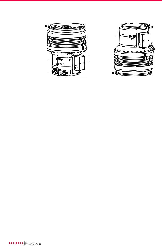
4.2 Function
The turbopumps HiPace 2300 form a complete unit together with the electronic drive unit. The voltage is supplied via the integrated power supply pack.
|
H |
|
|
2 |
|
|
|
|
|
|
410 |
|
|
|
|
|
F |
43 |
|
|
|
|
|
|
|
|
|
|
4a |
|
|
415 |
|
F |
|
SG |
|
8 |
|
|
|
|
421 |
|
|
|
|
|
|
|
|
|
|
|
|
|
13 |
|
|
H |
|
|
|
|
|
|
13h |
|
|
|
Fig. 4: HiPace 2300 mit TC 1200 |
|
|
|
||
|
2 |
High vacuum flange |
13 |
Electronic drive unit TC 1200 |
410 |
Cooling water connection |
|
4a |
Sealing gas connection |
13h |
Mains connection "AC in" |
415 |
Fore-vacuum flange |
|
8 |
Operating fluid pump |
43 |
Venting screw |
421 |
Earthing connection |
Cooling |
● Water cooling |
|
|
|
|
|
|
In the case of excess temperature the electronic drive unit reduces the drive power au- |
|||||
|
tomatically. |
|
|
|
|
|
Rotor bearing |
Hybrid bearing turbopump |
|
|
|
|
|
|
● High vacuum side: maintenance-free permanent magnetic bearing |
|||||
|
● Fore-vacuum side: ceramic ball bearing |
|
|
|||
Drive |
Electronic drive unit TC 1200 |
|
|
|
||
10
Product description
4.3 Range of application
The pump HiPace 2300 must be installed and operated under the following ambient conditions:
Installation location |
weather protected (indoors) |
Protection class |
IP 54 |
Temperature |
+5 °C to +40 °C |
Relative humidity |
max. 80 %, at T ≤ 31 °C, to max. 50% at T ≤ 40 °C |
Atmospheric pressure |
75 kPa - 106 kPa |
Installation altitude |
2000 m max. |
Degree of pollution |
2 |
Permissible surrounding magnetic field |
≤7 mT |
Overvoltage category |
II |
Connection voltage |
100-120/200-240 (± 10%) V AC |
Remarks to ambient conditions
The denoted permissible ambient temperatures apply to operation of the turbopump at maximum permissible fore-vacuum pressure or gas throughput depending on the cooling method. The turbopump is intrinsically safe by a redundant temperature monitoring.
●By reducing the fore-vacuum pressure or gas throughput, the turbopump can be operated at higher ambient temperatures.
●If the maximum permissible operating temperature of the turbopump is exceeded, it reduces drive power first and switches off then, if necessary.
11

Installation
5 Installation
WARNING
Risk of the turbopump being torn-off
In case of sudden blocking of the rotor, torques of up to 16000 Nm can occur, which can lead with incorrect attachment to tearing the turbopump off. The energy released thereby can hurl the entire pump or fragments from their inside around the area. This can cause severest injuries (possibly resulting in death) and large property damage.
Precisely follow installation instructions.
Only use Pfeiffer Vacuum original components (accessories) for installation.
Installation and operation of accessories
Pfeiffer Vacuum pumps can be equipped with a series of adapted accessories. The installation, operation and maintenance of connected devices are described in detail in the operating instructions of the individual components.
For information on order numbers of components, see "Accessories".
Use original accessory parts only.
Operating fluid filling
The pump is delivered without operating fluid filling. The operating fluid is part of the delivery consignment.
Do not fill the pump with operating fluid until the installation is done on site!
5.1 Set-up
When installing the pump, observe the following conditions:
●the ambient conditions specified for the range of application
●The attachment of the pump at its bottom part is not permitted.
●It is not allowed to operate the device in systems where impact-like stresses and vibrations or periodically forces occur.
5.2Preparatory work
Ensure sufficient cooling for the turbopump.
Where magnetic fields > 7 mT are involved, a suitable shielding must be used. Check installation location and consult Pfeiffer Vacuum if needed!
The maximum permissible rotor temperature for the turbopump is 120 °C. If high temperatures arise for process reasons, the radiated heat input must not exceed 24 W. Install suitable screening sheets, if necessary (design information on request).
5.3 Assembly
●Ensure the greatest possible cleanliness when installing any high vacuum parts. Unclean components prolong the pump-down time.
●All flange components must be grease-free, dust-free and dry at installation.
12

Installation
Earthquake safety An earthquake can result in contact with the safety bearings. All forces occuring hereby are safely absorbed by the properly installed flange connections.
The vacuum chamber must be secured by the customer against shifting and tipping.
SC |
Vacuum chamber |
SC |
|
|
SC


Use of a splinter shield or protection screen
Vibration damper
Mounting orientation
SC |
SC = Safety Connection |
SC |
|
Fig. 5: Example: How to secure against shifting and tipping by external tremors
The installation of a Pfeiffer Vacuum centering ring with splinter shield or protection screen in the high vacuum flange protects the turbopump against foreign bodies coming from the chamber. The pumping speed is reduced.
|
Volume flow rate reduction in % |
|
||||
|
H2 |
|
He |
|
N2 |
Ar |
|
|
|
||||
Splinter shield DN 250 |
7 |
|
11 |
|
23 |
25 |
|
|
|
|
|
|
|
Protection screen DN 250 |
2 |
|
3 |
|
6 |
7 |
|
|
|
|
|
|
|
WARNING
Danger from the turbopump and vibration damper being torn-off
In case of sudden blocking of the rotor, an applied vibration damper cannot compensate any of the occurring forces. There is a danger of the turbopump being torn-off and thereby resulting severest injuries and property damages. Applicable safeguards must be taken to compensate possible occurring torques.
Definitely consult with Pfeiffer Vacuum.
Do not exceed the max. permissible temperature at the vibration damper (100° C).
NOTICE
Observe type-specific mounting orientations!
Incorrect mounting orientations result in contamination of the process vacuum or damage to the pump.
Pay attention to the properties after the model designation on the name plate!
Observe the pictographs on the pump housing!
Do not transport or tilt the pump filled with operating fluid!
13
Loading...