

Page 1

8301
INSTRUCTION MANUAL
This instruction manual applies to machines
from serial number 2 777 829 and software
version 0398/003 onwards.
296-12-18 995/002
Betriebsanleitung engl. 10.11
Page 2

The parts list for the machines can be downloaded free of
charge from the internet address
www.pfaff-industrial.com/pfaff/de/service/downloads.
As an alternative to the internet download the adjustment manual can also be
ordered in book form under part no.296-12-18 995.
The reprinting, copying or translation of PFAFF Instruction Manuals, whether in whole or
in part, is only permitted with our previous authorization and with written reference to the
source.
PFAFF Industriesysteme
und Maschinen AG
Hans-Geiger-Str. 12 - IG Nord
D-67661 Kaiserslautern
Page 3

Contents
Contents ..................................................................................Page
1 Safety .................................................................................................................................... 5
1.01 Directives ............................................................................................................................... 5
1.02 General notes on safety ......................................................................................................... 5
1.03 Safety symbols ......................................................................................................................6
1.04 Important notes for the user .................................................................................................. 6
1.05 Operating and technical staff ................................................................................................. 7
1.05.01 Operating staff ....................................................................................................................... 7
1.05.02 Technical staff ........................................................................................................................ 7
1.06 Danger ...................................................................................................................................8
2 Proper use............................................................................................................................. 9
3 Specifi cations ..................................................................................................................... 10
4 Disposal of Machine ...........................................................................................................11
5 Transportation, packing and storage ................................................................................ 12
5.01 Transportation to customer‘s premises ............................................................................... 12
5.02 Transportation inside the customer‘s premises ................................................................... 12
5.03 Disposal of packing materials ..............................................................................................12
5.04 Storage ................................................................................................................................ 12
6 Explanation of symbols ..................................................................................................... 13
7 Controls .............................................................................................................................. 14
7.01 Summary of control elements ............................................................................................. 14
7.02 Main switch ......................................................................................................................... 15
7.03 Pedal .................................................................................................................................... 15
7.04 Setting wheel for roller distance ..........................................................................................16
7.05 Setting wheel for roller pressure.......................................................................................... 16
7.06 Control panel ........................................................................................................................ 17
7.06.01 Symbols on the display ........................................................................................................ 17
7.06.02 Function keys ....................................................................................................................... 18
8 Installation and commissioning ....................................................................................... 19
8.01 Installation ............................................................................................................................ 19
8.01 Adjusting the table-top height .............................................................................................. 19
8.02 Commissioning .................................................................................................................... 20
8.03 Switching the machine on/off .............................................................................................. 20
9 Preparation ......................................................................................................................... 21
9.01 Programme call-up and modifi cation .................................................................................... 21
9.02 Setting roller distance and roller pressure ........................................................................... 21
9.03 Setting the differential transport .......................................................................................... 22
9.04 Additional transport rollers (optional) ................................................................................... 22
9.05 Inserting and removing the SD-memory card ...................................................................... 23
10 Sealing ................................................................................................................................ 24
10.01 Sealing principle .................................................................................................................. 24
10.02 Error messages .................................................................................................................... 25
3
Page 4

Contents
Contents ..................................................................................Page
11 Input .................................................................................................................................... 26
11 .01 Access codes ....................................................................................................................... 26
11 .01.01 Inputting the access code .................................................................................................... 26
11 .01.02 Modifying the access code .................................................................................................. 27
11 .01.03 Assigning access rights ....................................................................................................... 27
11 .02 Example of a parameter input .............................................................................................. 28
11 .03 List of parameters ................................................................................................................ 29
11 .04 Error messages in the display ..............................................................................................33
11 .05 Programme Management .................................................................................................... 34
11 .05.01 Calling up Programme Management ................................................................................... 34
11 .05.02 Copying machine data to the SD card .................................................................................. 35
11 .05.03 Copying data from the SD card to the machine memory .................................................... 36
11 .05.04 Formatting the SD memory card ......................................................................................... 37
11 .06 Internet update of the machine software ............................................................................ 38
11 .06.01 Update with null modem cable ............................................................................................38
11 .06.02 Update with SD-card ............................................................................................................ 39
12 Care and Maintenance ....................................................................................................... 41
12.01 Maintenance intervals .......................................................................................................... 41
12.02 Cleaning the feed rollers ...................................................................................................... 41
12.03 Checking/adjusting the air pressure ..................................................................................... 42
12.04 Cleaning the air fi lter of the air-fi lter/lubricator ..................................................................... 42
12.05 Exchanging the transport rollers .......................................................................................... 43
13 Connection diagram .......................................................................................................... 44
13.01 Pneumatics-switch diagram ................................................................................................. 44
13.02 Circuit diagrams ................................................................................................................... 45
4
Page 5

Safety
1 Safety
.01 Directives
1
This machine is constructed in accordance with the European regulations indicated in the
conformity and manufacturer’s declarations.
In addition to this instruction manual, please also observe all generally accepted, statutory
and other legal requirements, including those of the user’s country, and the applicable
pollution control regulations! The valid regulations of the regional social insurance society for
occupational accidents or other supervisory authorities are to be strictly adhered to!
1.02 General notes on safety
● The machine may only be operated by adequately trained operators and only after these
have read the appropriate Instruction Manual!
● The danger and safety instructions attached to the machine must be followed!
● The machine may only be used for the purpose intended and may not be operated wit-
hout its safety devices. All relevant safety regulations must be adhered to.
● When changing the feed rollers or the hot air nozzle, when leaving the machine unatten-
ded or during maintenance work, the machine must be disconnected from the power
supply by pulling out the plug!
● The daily maintenance work may only be carried out by appropriately trained personnel!
● During repair and maintenance work on pneumatic devices the machine must be discon-
nected from the pneumatic supply system! The only exceptions permitted are during ad-
justment work and function tests carried out by appropriately trained personnel!
● Repairs and special maintenance work may only be carried out by qualifi ed service staff
or appropriately trained personnel!
● Work on electrical equipment may only be carried out by appropriately trained personnel!
● Work is not permitted on parts and equipment which are connected to the power supply!
Exceptions to this rule are found in the regulations EN 50110.
● Modifi cations and alterations to the machine may only be carried out under observance
of all the relevant safety operations!
● Only spare parts which have been approved by us are to be used for repairs! We draw
special attention to the fact that spare parts and accessories not supplied by us have not
been subjected to testing nor approval by us. Fitting and/or use of any such parts may
cause negative changes to the design characteristics of the machine. We shall not accept
any liability for damage caused by the use of non-original parts.
5
Page 6
Safety
o
o
o
o
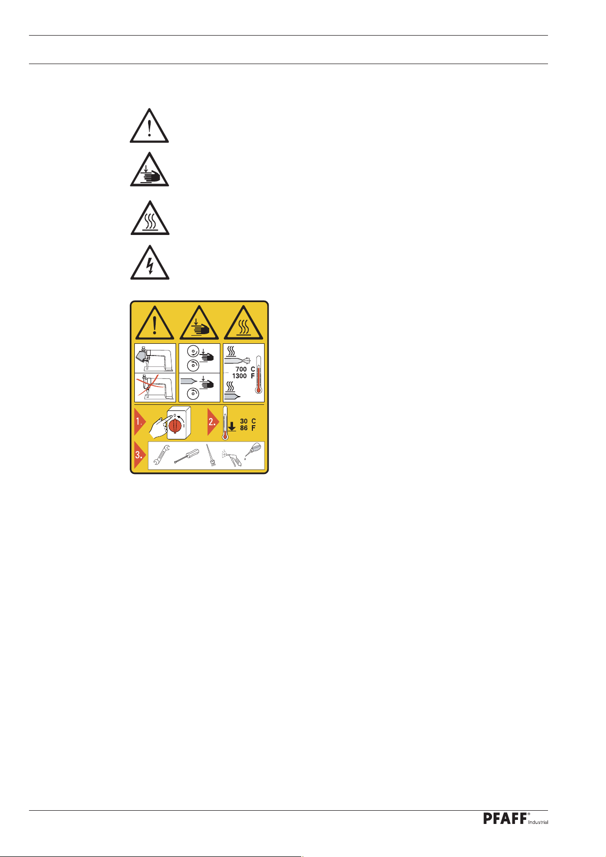
1.03 Safety symbols
Danger!
Special points to observe.
Danger of hands being crushed!
Danger of burns from hot surface!
Danger from electric voltage!
Caution
Do not operate without fi nger guard and safety
devices.
1.04 Important notes for the user
● This instruction manual belongs to the equipment of the machine and must be available
to the operating staff at all times.
● This instruction manual must be read before the machine is operated for the fi rst time.
● Both operating and technical staff must be instructed on the safety devices of the machi-
ne and on safe working methods.
● It is the duty of the user to operate the machine in perfect running order only.
● The user must ensure that none of the safety devices are removed nor put out of wor-
king order.
Turn off the main switch and let the machine cool
down before any setting up, maintenance or cleaning
work!
● The user must ensure that only authorized persons operate and work on the machine.
● The user must make sure there is no high-frequency welding equipment being operated
in direct proximity to the machine that exceeds the EMC limit values according to
EN 60204-31 for the machine.
For further information please refer to your PFAFF agency.
6
Page 7

Safety
1.05 Operating and technical staff
1
.05.01 Operating staff
Operating staff are the persons responsible for setting up, operating and cleaning the machi-
ne and for removing any disturbances in the sewing area.
The operating staff is obliged to observe the following points, and must:
● always observe the notes on safety in this instruction manual!
● avoid using any working methods which adversely affect the safety of the machine!
● avoid wearing loose-fi tting clothing or jewelry such as necklaces or rings!
● also ensure that only authorized persons are allowed near the danger area of the machine!
● immediately report to the user any changes to the machine that may affect its safety!
1.05.02 Technical staff
Technical staff are persons who have been trained in electrical engineering, electronics and
mechanical engineering. They are responsible for lubricating, servicing and repairing the ma-
chine.
The technical staff is obliged to observe the following points, and must:
● always observe the notes on safety in this instruction manual!
● switch off the on/off switch before carrying out any maintenance and repair work on the
machine!
● never work on parts or equipment still connected to the power supply! Exceptions to this
are only permissible according to regulations EN 50110.
● replace all safety covers after maintenance and repair work!
7
Page 8
Safety
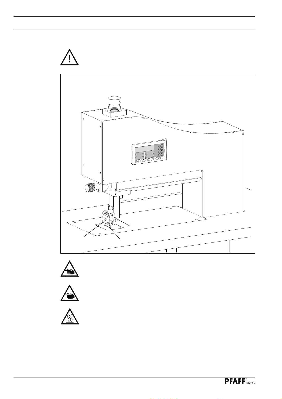
1.06 Danger
When the machine is in operation, a work area of 1 m must be kept free in
front of and behind the machine, so that access to the machine is possible at all
times without diffi culty.
P
TE
F1
P6
P5
P4
P3
P2
P1
Fig. 1 - 01
1
2
Do not operate the machine without fi nger guard 1!
Danger of crushing if the fi ngers are drawn in!
During operation do not place your hands in the area of feed roller 2 and
sonotrode 3! Danger of fi ngers being drawn in and crushed!
During operation do not touch sonotrode 3!
Danger of burns from the heat-generating surface!
3
8
Page 9

Proper use
2 Proper use
The PFAFF 8301 is an ultrasonic welding machine for the continuous welding of thin
thermoplastic materials, e.g. fl eeces, felts, meshed or woven fabrics.
Any and all uses of this machine which have not been approved of by the
manufacturer are considered to be inappropriate! The manufacturer cannot be
held liable for any damage caused by the inappropriate use of the machine!
The appropriate use of the machine includes the observance of all operational,
adjustment, maintenance and repair measures required by the manufacturer!
9
Page 10

Specifi cations
3 Specifi cations▲
Dimensions:
Width: ............................................................................................................ approx. 1200 mm
Depth: ............................................................................................................. approx.. 800 mm
Height: ........................................................................................................... approx. 1310 mm
Passage width: ................................................................................................. approx. 410 mm
Max. through-passage under transport rollers: .............................................................. 20 mm
Connectivity data
Operating voltage: ..................................................................230 V ± 10%, 50/60 Hz, 1-phase
Max. input power: ......................................................................................................... 1000 VA
Mains protection: ................................................................................................................ 16 A
Leakage current: .......................................................................................................... < 5 mA
Performance data:
Sealing pressure: .....................................................................................................100 - 500 N
Sealing power: ........................................................................................................ max. 400 W
Sealing speed: .................................................................................................. 0,1 - 10 m/min*
◆
Noise data
Emission sound level at the workplace: .............................................................LpA < 70 dB(A)
(Noise measurement in acc. with DIN 45 635-48-A-1, ISO 11204, ISO 3744, ISO 4871)
Net weight: ........................................................................................................approx. 120 kg
▲
Subject to alterations
* Depending on transport roller diameter; stated max. value for 80 mm roller diameter
■
KpA = 2,5 dB
◆
Due to the use of network fi lters there is a nominal leakage current of < 5 mA.
■
10
Page 11

Disposal of Machine
4 Disposal of Machine
● Proper disposal of the machine is the responsibility of the customer.
● The materials used for the machine are steel, aluminium, brass and various plastic
materials. The electrical equipment comprises plastic materials and copper.
● The machine is to be disposed of according to the locally valid pollution control regula-
tions; if necessary, a specialist ist to be commissioned.
Care must be taken that parts soiled with lubricants are disposed of separately
according to the locally valid pollution control regulations!
11
Page 12

Transportation, packing and storage
5 Transportation, packing and storage
5
.01 Transportation to customer‘s premises
The machines are delivered completely packed.
5.02 Transportation inside the customer‘s premises
The manufacturer cannot be made liable for transportation inside the customer‘s premises
nor to other operating locations. It must be ensured that the machines are only transported
in an upright position.
5.03 Disposal of packing materials
The packing materials of this machine comprise paper, cardboard and VCE fi bre. Proper dis-
posal of the packing material is the responsibility of the customer.
5.04 Storage
If the machine is not in use, it can be stored as it is for a period of up to six months, but It
should be protected against dust and moisture.
If the machine is stored for longer periods, the individual parts, especially the surfaces of
moving parts, must be protected against corrosion, e.g. by a fi lm of oil.
12
Page 13

Explanation of symbols
6 Explanation of symbols
In this instruction manual, work to be carried out or important information is accentuated by
symbols. These symbols have the following meanings:
Note, information
Cleaning, care
Lubrication
Maintenance, repairs, adjustment, service work
(only to be carried out by technical staff)
13
Page 14

Controls
7 Controls
7
.01 Summary of control elements
5
P
TE
F1
P6
P5
P4
P3
P2
4
P1
2
6
7
Fig. 7 - 01
● Main switch 1, see Chapter 7.02
● Control panel 2, see Chapter 7.06
● Pedal 3, see Chapter 7.03
● Setting wheel 4 for roller distance, see Chapter 7.04
1
3
14
● Setting wheel 5 for roller pressure
● Upper transport roller 6
● Sonotrode 7
Page 15
Controls
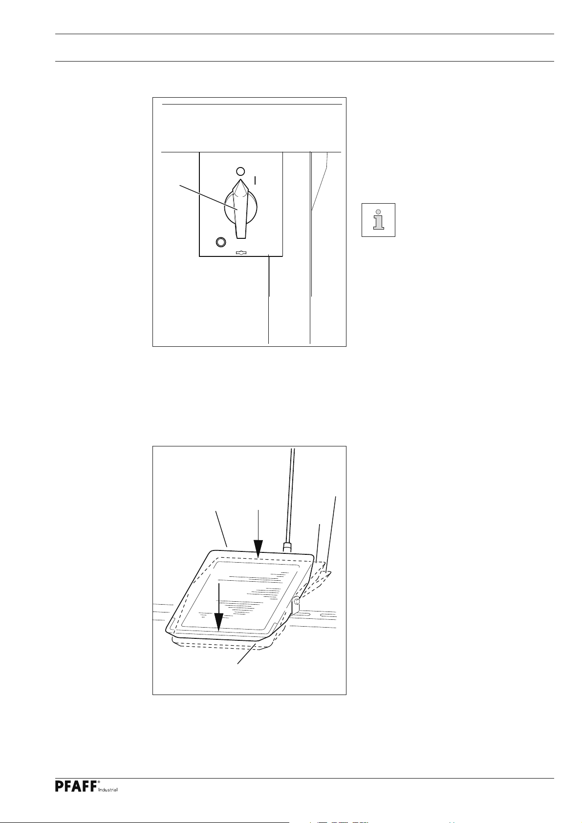
7.02 Main switch
● The machine is switched on or off by
turning main switch 1.
Position "0": Machine is switched off
Position "I": Machine is switched on
1
Fig. 7 - 02
7.03 Pedal
About 30 seconds after the
machine is switched on,
the last basic menu called
up before the machine was
switched off will be displayed.
Foot switch functions
Fig. 7 - 03
0 = Rest position (welding stops)
+2
0
+1
+1 = Transport roller is lowered to welding
position.
+2 = Press and hold treadle:
Welding process begins and runs as
long as the treadle is pressed.
-1 = Lift transport roller
-1
15
Page 16

Controls
7.04 Setting wheel for roller distance
Fig. 7 - 04
● The distance between the upper
transport roller and the sonotrode is
adjusted by turning the setting wheel 1.
Sonotrode 2 and transport
roller 3 must never be in direct
contact!
F1
P6
P5
P4
P3
P2
P1
Danger of machine damage!
Exempted are steel sonotrodes.
1
3
2
7.05 Setting wheel for roller pressure
1
F1
P6
P5
P4
P3
P2
P1
Fig. 7 - 05
● Roller pressure is adjusted by turning the
setting wheel 1.
● The roller pressure is shown on the scale
of the setting wheel.
● This roller pressure value can be input in
the display for each programme, but only
serves for memory purposes.
P
TE
16
Page 17

Controls
7.06 Control panel
The control panel is used to display and access machine functions for set-up and welding, to
enter parameter values and to read error messages and service settings.
1
P
2
P3
Fig. 7 - 05
P2
3
P1
P5
P4
F1
P6
The control panel has the following control and display elements:
● The display screen 1 consists of a two-line, alphanumerical LCD display with 16 symbols
per line and is used to show relevant information and selection parameters.
● The plus-minus keys 2 are used to select or alter the functions and parameters shown on
the display.
● The function keys 3 are used to switch the relevant function on or off. Activated functions
are shown in each case by an illuminated LED.
TE
7.06.01 Symbols on the display
In addition to texts and set values, the following symbols are shown on the display
Current program number
Maximum speed in current seam sector
17
Page 18

Controls
7.06.02 Function keys
The function keys described in the following are used primarily for the
activation/ deactivation of machine functions. If the function is turned on,
the corresponding key LED lights up.
Where a value is to be set for the activated function, this can be done via
the +/- keys 2.
Pressing and holding the +/- keys will initially change the number value shown
above the key slowly. Holding the +/- key longer will speed up the speed at
which the number value changes.
The following description contains the relevant +/- keys as shown here.
Stop
The machine is stopped during the welding process.
Low/lift the transport roller
When activated, the transport rollers are lifted or lowered.
P1
to
P6
F1
TE
P
Programming keys
Programmes 1 - 6 are called up with these keys.
Alternatively, the programmes 0 - 19 can be called up via the left +/- keys.
F1
Transport rollers are blocked (e.g. when replacing the transport rollers).
Scroll
Pressing and holding this key will scroll through the following sub-menus:
Amplitude, Speed, Welding Pressure (only advance registration function), Differential,
Parameters, SD Card.
TE
This key allows toggling between Production mode (LED off) and Input mode (LED on.
P
Here, a test programme can be created.
18
Page 19

Installation and commissioning
8 Installation and commissioning
After the machine has been unpacked, check it for any damages caused during transportation. If there are any damages, please notify the transport company and your
local PFAFF agency.
The machine must only be installed and commissioned by qualifi ed personnel.
All relevant safety regulations must be strictly adhered to!
8.01 Installation
The site where the machine is installed must be provided with suitable connections for the
electric current, see Chapter 3 Specifi cations.
It must also be ensured that the standing surface of the machine site is fi rm and horizontal,
and that suffi cient lighting is provided.
8.01 Adjusting the table-top height
1
Fig. 8 - 01
● Slide the machine off the pallet.
● Loosen screw 1.
2
3
1
● Adjust the table tap to the required working height by increasing or reducing the height
of the stand and then level the table-top horizontally.
To avoid the stand tilting, adjust it evenly on both sides.
● To guarantee that the stand is standing securely, it must be positioned securely on the
ground with all four legs.
● The height can be adjusted with screw 2 ( nut 3).
19
Page 20

Installation and commissioning
8.02 Commissioning
● Thoroughly clean machine as needed.
● Check the machine, particularly the electrical wiring, for any damage.
● Have skilled personnel check if the machine can be operated with the available mains
voltage.
Do not operate the machine if there is any discrepancy.
The machine may only be connected to an earthed socket!
● Connect the machine to the compressed air system. The manometer should display
a pressure of 6 bar. Set this value, if needed (see Section 12.03 "Checking the air
pressure of the maintenance unit").
8.03 Switching the machine on/off
● Turn the main switch in position "I" (see Section 7.02 "Main switch") to turn the machine
on.
20
Page 21

Preparation
9 Preparation
All regulations and notes in this Service Manual must be observed!
Special attention must be paid to the safety regulations!
All setting-up work must only be carried out by personnel with the appropriate
training!
9.01 Programme call-up and modifi cation
● Switch machine on.
Ampl
2 75.0% 2.0
P3
P2
P1
P5
P4
F1
P6
● Call up the programme with the desired welding parameters (0 - 19) via the keys P1 to P6
P1
to
P6
or via the +/- keys on the left.
● The values displayed for Amplitude and Speed can be modifi ed directly via the
corresponding +/- keys as needed.
● Once modifi ed, these values will be saved.
9.02 Setting roller distance and roller pressure
● Switch machine on.
● Call up the menu for inputting the roller pressure.
● Lower the transport rollers and set the roller distance as described in Section 7.04.
P
TE
● Set the roller pressure (see Section 7.05).
The roller pressure show on the scale can be entered on the display via the relevant
+/- keys for each programme, but only serve as a memory aid.
Push Diff
P
2 130 0%
P3
P2
P1
P5
P4
F1
P6
TE
21
Page 22

Preparation
9.03 Setting the differential transport
● Switch machine on.
● Call up the menu for inputting the differential transport.
● A differential transport value can be entered via the corresponding +/- keys for each
programme.
1.0 % means that the upper transport roller will run 1% faster than the sonotrode.
-1.0 % means that the upper transport roller will run 1% slower than the sonotrode.
Push Diff
2 130 1.0%
P3
P2
P1
P5
P4
F1
P6
9.04 Additional transport rollers (optional)
P
TE
22
1
2
Fig. 9 - 04
● The two additional transport rollers 1 can be lifted or lowered as needed via the setting
screws 2.
Page 23

Preparation
9.05 Inserting and removing the SD-memory card
Inserting the SD-memory card
● Open cover 1.
1
● Insert SD-memory card 2 into the card
slot with the label at the front.
P6
Fig. 9 - 05
P
2
● Close cover 1 again.
2 GB
max.
Removing the SD-memory card
● Open cover 1.
F1
TE
● Press the edge of the SD-memory card 2
lightly – the SD-card is ejected.
● Close cover 1 again.
3
By moving slide 3 it is possible to activate (position "LOCK") or deactivate
the write protection function of the SD-memory card. To store, process or
delete data on the SD-memory card, the write protection function must be
deactivated.
23
Page 24

Sealing
10 Sealing
10.01 Sealing principle
The machine may only be operated by properly instructed personnel. The
operating personnel must make sure that only authorised persons are in the
danger zone of the machine.
Due to the vibrations of the sonotrode, the plies of the workpiece are mechanically "ham-
mered" in the seam area. Through the hammering motions of the sonotrode the workpiece
is heated until it becomes viscous and at the same time it is pressed and fed to form the
seam.
In order to achieve optimum sealing results, certain conditions concerning the workpiece
and the machine settings have to be fulfi lled.
The workpiece must be:
- sealable (thermoplast),
-- suitable for processing with the PFAFF 8301 with regard to thickness and properties and
- clean in the seam area.
The basic requirements on the machine are:
- selection of the correct feed roller and setting
- roller pressure
- sealing power
- sealing speed and
- roller gap (distance of the anvil roller to the sonotrode during sealing).
All settings of the sealing machine are always dependent on the type being
sealed and the ambient temperature. As a result of the infl uence of the
individual parameters on each other, optimum settings can only be determined
by means of test sealing operations.
All settings required for the welding process are entered or displayed in the
control panel.
24
Page 25

Sealing
10.02 Error messages
When an error occurs, the text "ERROR" appears on the display together with an error
code and short instructions. In addition the diode in the memory card slot lights up red
(see arrow). An explanation of the error codes can be found in the Chapter 11.04 Error
message explanations.
ERROR: 308
P
RESET
P3
P2
P1
P5
P4
F1
P6
● Correct the error.
● Acknowledge the correction of the error by pressing the corresponding plus - key or by
switching the machine off and on.
● The diode in the memory card slot (see arrow) turns yellow again
TE
25
Page 26

Input
11 Input
11
.01 Access codes
The call-up of each individual parameter level can be blocked by inputting a four digit access
code. The access code can be modifi ed at any time. The access code is set to "8301" ex
works.
11 .01.01 Inputting the access code
An input prompt for the access code is displayed for functions called up in Input mode that
have an access code assigned.
TE
PINCODE:
P
8 3 0 1
P3
P2
P1
P5
P4
F1
P6
● ZuEnter the access code via the corresponding +/- keys.
● Finish your input by pressing the key "TE" (the machine will switch to "Production" mode).
Once the access code has been entered, all protected functions are freely
accessible until the machine is switched off.
TE
26
Page 27

Input
11 .01.02 Modifying the access code
● Call up the menu Parameters in Input mode.
● Call up parameter "811".
● Enter the access code if needed (see Section 11.01.01 "Inputting the access code").
No VAL
811 8301
P3
P2
P1
● Modify the access code via the corresponding +/- keys.
TE
● Finish your input by pressing the key "TE" (the machine will switch to "Production" mode).
Remember the code!
Protected functions cannot be called up without the corresponding code!
In this case request support from the PFAFF service centre.
11 .01.03 Assigning access rights
P
F1
P6
P5
P4
TE
TE
● Call up the menu Parameters in Input mode.
● Call up parameters "801" to "809" (see Section 11.03 "List of parameters").
● Enter the access code if needed (see Section 11.01.01 "Inputting the access code").
No VAL
P
801 OFF
P3
P2
P1
P5
P4
F1
P6
● Allow (ON) or disallow (OFF) access via the corresponding +/- key.
● Finish your input by pressing the key "TE" (the machine will switch to "Production" mode).
TE
27
Page 28

Input
11 .02 Example of a parameter input
TE
● Call up the menu Parameters in Input mode.
● Enter the access code if needed (see Section 11.01.01 "Inputting the access code").
No VAL
P
001 OFF
P3
P2
P1
P5
P4
F1
P6
● Select the desired parameter via the corresponding +/- keys, e.g. 004 key tone ON/OFF.
No VAL
TE
P
004 OFF
TE
P3
P2
P1
P5
P4
F1
P6
TE
● Switch the key tone to ON via the corresponding +/- key.
No VAL
P
004 ON
P3
P2
P1
P5
P4
F1
P6
● Finish the input by pressing TE. (Machine switches to Production mode).
An overview with explanations for all the parameters can be found in Section
11.03 "List of parameters".
TE
28
Page 29

Input
11 .03 List of parameters
Parameter values must only be modifi ed by relevantly trained personnel!
000
100
200
Group
Parameter
Description
Setting
001 Start delay [ms] ON/OFF ON - OFF
10 - 800
002 Reverse after stop [mm] ON - OFF
1 - 15
003 Treadle mode
00
004 Key tome ON - OFF ON
101 Display main processer software version - -
103 Display control panel software version - -
201 Speed max. [1/10 m/min] 1 - 200 200
202 Sonotrode drive
1 = Motor to gear factor.
2 = Number of teeth - motor side
3 = Number of teeth - sonotrode side
4 = Sonotrodes ø [1/10 mm]
2
5 = Acceleration factor [1/10 1/s
]
range
Set value
ON
300
ON
2
8
18
30
1040
2000
203 Anvil wheel drive
1 = Motor to gear factor.
2 = Number of teeth - motor side
3 = Number of teeth - sonotrode side
4 = Sonotrodes ø [1/10 mm]
5 = Acceleration factor [1/10 1/s
204 Torque (motor current)
2
]
1 - 3 2
8
1
1
650
1 = Reduced current
2 = Normal current
3 = Max. current (only for a short time)
29
Page 30

Input
600
Group
Parameter
601
Description
Display inputs
This function allows the checking of the digital
inputs. "IN" denotes the input numbers (1 - 16).
The associated switch state is displayed under
"VAL".
IN VAL
1 (X5 D-SUB Pin 1) IN1, roller down
(ON = Roller down)
2
3 X5 D-SUB Pin 3) Ultrasonic generator
error (ON = Error)
4
5
6
7
8
9
10
11
12
13
14
15
16
Setting
range
Set value
30
602 Display special inputs
This function allows the display of the special
inputs for "Treadle"; "IN" denotes the inputs
(PED). The associated switch state is displayed
under "VAL".
IN VAL
PED Treadle
(Speed control unit -1; 0; +1; +2)
Page 31

Input
600
Group
Parameter
603 Switch outputs
Description
This function allows the switching of the digital
outputs. "OUT" denotes the selected output
(1 - 16). The selected output (S) is set under
"VAL" via the +/- key (+), and also reset (R) via
the +/- key (-). Locks are checked. Unassigned
outputs are not switched.
OUT VAL
1 S/R
2 S/R
3 S/R X13 D-SUB Pin 5) roller up/down
4 S/R
5 S/R
6 S/R X13 D-SUB Pin 8) blower ON
7 S/R X13 D-SUB Pin 9) sonotrode fan
8 S/R
9 S/R
10 S/R
11 S/R
12 S/R
13 S/R
14 S/R
15 S/R
16 S/R
Setting
range
Set value
604 Move step motors
The step motors SM1 (X-axis) and SM2 (Y-axis)
are moved individually via their respective +/-
keys. Locks are not checked.
605 Cold start (RESET)
The controls carry out a cold start (RESET) via
this function; data is re-initialised. Once this
function is selected, the machine must be
switched OFF and ON again.
31
Page 32

Input
800
Group
Parameter
801 Access authorisation group 000 ON - OFF ON
802 Access authorisation group 100 ON - OFF ON
803 Access authorisation group 200 ON - OFF OFF
807 Access authorisation group 600 ON - OFF OFF
808 Access authorisation group 700 ON - OFF OFF
809 Access authorisation group 800 ON - OFF OFF
Description
Function groups can be released (ON) or locked
(OFF) for manipulation. The parameters of a
locked function group can only be modifi ed
after a valid access code has been entered.
Once a valid access code has been entered,
the lock will remain deactivated until the
machine is switched off.
Setting
range
Set value
811
Access code
The access code can be modifi ed via this
parameter. Upon initial delivery of the machine
ex works, the access code is set to "8301".
8301
32
Page 33

Input
11 .04 Error messages in the display
The following error messages are shown in the display of the control panel.
ERROR: 1 Processor error STACK_OVERFLOW
ERROR: 2 Processor error STACK_UNDERFLOW
ERROR: 3 Processor error UNDEF_OPCODE
ERROR: 4 Processor error PROTECTION_FAULT
ERROR: 5 Processor error ILLEGAL_WORD_OPERAND
ERROR: 6 Processor error ILLEGAL_INSTRUCTION
ERROR: 7 Processor error ILLEGAL_BUS_ACCESS
ERROR: 8 Processor error NMI
ERROR: 50 Wrong control panel
ERROR: 51 Incorrect machine class in OTE
ERROR: 52 Wrong software for main drive
ERROR: 101 Mains voltage
ERROR: 102 Power supply overload
ERROR: 103 24 V to low
ERROR: 230 Error ultrasonic generator
ERROR: 308 The lower safety limit switch was not reached when roller was lowered
(unauthorised object in the way or lower limit switch not mounted
correctly)
ERROR: 309 The lower safety limit switch did not open when the roller was lifted
ERROR: 416 SD card reader error
1: No SD card inserted
2: Incorrect SD card (does not match machine)
3: SD card incorrectly inserted
4: SD card is write-protected
5: Data error on SD card
6: Formatting has failed
7: File does not match machine
8: Incorrect fi le size
9: Transfer error
10: File could not be deleted
33
Page 34

Input
11 .05 Programme Management
In Programme Management, confi guration and machine data, and programmes stored in the
machine memory or on the inserted SD card can be deleted or copied.
You can insert commercially available standard SD cards with max. 2 GB capacity into the
control panel. The data is stored in machine-relevant sub-directories. The insertion and
removal of SD cards is described in Section 9.05.
The following data types are stored:
● Confi guration data in fi le KD.
● The programmes 0 - 19 and the machine data in fi le MD.
If the SD card is to be formatted via PC, select the format "FAT16". Alternatively, the SD
memory card can also be formatted using the formatting function on the corresponding
machine, see Section 11.05.05 "Formatting the SD card".
11 .05.01 Calling up Programme Management
TE
● Switch machine on.
● Call up mode "Entry"
● Call up "Programme Management"
P
COPY
P3
P2
P1
P5
P4
F1
P6
The fi rst menu item is displayed when "Programme Management" is called up.
The menu item selection is confi rmed via the "Enter" function; press the right + key to
confi rm. In the context of this example, the machine memory will now be displayed.
Browse through the other menu items by pressing the left +/- key (see also following
sections).
TE
34
The following menu items are available in program management:
● Copying machine data to the SD card
● Copying data from the SD card to the machine memory
● Formatting the SD memory card
Page 35

Input
11 .05.02 Copying machine data to the SD card
TE
● Call up mode "Entry"
● Call up "Programme Management"
P
COPY
P3
P2
P1
P5
P4
F1
P6
● Press and hold the +/- keys until the corresponding menu item is displayed.
● Select the menu item via the "Enter" function, press the right + key to confi rm.
TE
P
COPY ALL
P3
P2
P1
P5
P4
F1
P6
TE
● Select the data to be copied from the machine memory to the SD card by pressing the
corresponding +/- keys:
KD = Confi guration fi les
MD = Machine parameters and programmes 0 - 19
ALL = all fi les
● Start the copy process via the "Enter" function, press the right + key to confi rm.
If the data to be copied already exists, a security prompt will be displayed
before overwriting. The copy process is confi rmed by pressing the right + key.
The copy process can be cancelled by pressing the right - key.
● Other menu items in "Programme Management" are called up by pressing the left +/-
keys.
35
Page 36

Input
11 .05.03 Copying data from the SD card to the machine memory
TE
● Call up mode "Entry"
● Call up "Programme Management"
P
COPY
P3
P2
P1
P5
P4
F1
P6
● Press and hold the +/- keys until the corresponding menu item is displayed.
● Select the menu item via the "Enter" function, press the right + key to confi rm.
TE
P
COPY MD
P3
P2
P1
P5
P4
F1
P6
TE
● Select the data to be copied from the SD card to the machine memory by pressing the
corresponding +/- keys:
KD = Confi guration fi les
MD = Machine parameters and programmes 0 - 19
ALL = all fi les
● Start the copy process via the "Enter" function, press the right + key to confi rm.
If the data to be copied already exists, a security prompt will be displayed
before overwriting. The copy process is confi rmed by pressing the right + key.
The copy process can be cancelled by pressing the right - key.
● Other menu items in "Programme Management" are called up by pressing the left
+/- keys.
36
Page 37

Input
11 .05.04 Formatting the SD memory card
TE
● Call up mode "Entry"
● Call up "Programme Management"
P
FORMAT
P3
P2
P1
P5
P4
F1
P6
● Press and hold the left +/- keys until the corresponding menu item is displayed.
● Start the formatting process via the "Enter" function, press the right + key to confi rm.
Before the start of formatting, a prompt for confi rmation will be displayed. The
formatting process is confi rmed by pressing the right + key. The formatting
process can be cancelled by pressing the right - key.
TE
● Other menu items in "Programme Management" are called up by pressing the left +/-
keys.
37
Page 38

Input
11 .06 Internet update of the machine software
The machine software can be updated with PFAFF fl ash programming. For this purpose
the PFP boot program (from version 3.25 on) and the appropriate control software for
the machine type must be installed on a PC. The transfer of the data to the machine can
be carried out with a null modem cable (part no. 91-291 998-91) or with an SD-card.
The SD-card must be formatted in the FAT16 format and must not exceed a capacity of
2 GBytes.
The PFP boot program and the control software of the machine type can
be downloaded from the PFAFF-homepage using the following path:
www.pfaff-industrial.com/pfaff/de/service/downloads
11 .06.01 Update with null modem cable
● After downloading the PFP tool and the control software, open the PFP program.
● Select the machine type and under control unit P320.
● The software version is displayed under report.
● Switch off the machine.
● Connect the PC (serial interface or appropriate USB-adapter) and the machine control unit
(RS232). To do so disconnect the plug of the control panel.
While the machine software is being updated, no setting up, maintenance or
adjustment work may be carried out on the machine!
38
● Switch on the machine, keeping the boot key 1 pressed.
● Press the "OK" button.
The software update is carried out, the update progress is shown on the bar display of
the PFP boot program.
● During the updating process the machine must not be switched off.
● When the update has been completed, switch off the machine and end the PFP boot
program.
● End the connection between the PC and the machine control unit and reconnect the
control panel to the machine control unit.
Page 39

Input
● Switch on the machine
● A plausibility control is carried out and, if necessary, a cold start.
More information and assi-
stance is at your disposal in the
fi le "PFPHILFE.TXT", which can
be called up from the PFP boot
program by pressing the "help"
button.
1
Fig. 11 - 06
11 .06.02 Update with SD-card
● After downloading the PFP tool and the control software, open the PFP program.
● Select the machine type and under control unit SD-CARD.
● The software version is displayed under report.
● Under programming copy the software to the drive with the SD-card.
39
Page 40

Input
● With the machine switched off insert the SD-card into the control panel.
P
P3
P2
P1
P5
P4
F1
P6
TE
To update the machine software carry out the following steps:
While the machine software is being updated, no setting up, maintenance or
adjustment work may be carried out on the machine!
● Switch on the machine, keeping the boot
key 1 pressed.
● Press the "TE" key.
The software update is carried out. Duri-
ng the updating process the diode in the
memory card slot fl ashes.
● During the updating process the machine
must not be switched off.
1
● When the update has been completed,
switch off the machine and remove the
SD-card.
40
● Switch on the machine
● A plausibility control is carried out and, if
necessary, a cold start.
Fig. 11 - 06
More information and assistance is at your disposal in the fi le "PFPHILFE.TXT",
which can be called up from the PFP boot program by pressing the "help"
button.
Page 41

Care and Maintenance
12 Care and Maintenance
12
.01 Maintenance intervals
Check the air pressure .........................................................................daily, before start-up
Clean the air fi lter of the maintenance unit .........................................................as required
Clean the feed rollers ..........................................................................................as required
During all cleaning work the machine must be disconnected from the power
supply by switching off the main switch or pulling out the plug!
Danger of injury if the machine is started accidentally!
12.02 Cleaning the feed rollers
● When necessary, remove any sealing re-
sidues left on the top and bottom feed
rollers 1 and 2.
2
Fig. 12 - 02
F1
P6
P5
P4
P3
P2
P1
1
41
Page 42

Care and Maintenance
.03 Checking/adjusting the air pressure
12
● Before operating the machine, always
2
check the air pressure on gauge1.
● Gauge 1 must show a pressure of 6 bar.
● If necessary adjust to this reading.
1
Fig. 12 - 03
12
.04 Cleaning the air fi lter of the air-fi lter/lubricator
8
6
4
2
0
10
100
150
50
0
12
200
14
230
16
● To do so, pull knob 2 upwards and turn
it so that the gauge shows a pressure of
6 bar
Fig. 12 - 04
Switch the machine off!
Disconnect the air hose at the
air-fi lter/lubricator.
To drain water bowl:
● Water bowl 1 drains itself automatically
whe the compressed-air hose is discon-
nected from the air-fi lter/lubricator.
1
Cleaning fi lter:
● Unscrew water bowl 1 and take out
fi lter 2.
2
● Clean fi lter 2 with compressed air or iso-
propyl alcohol (part No. 95-665 735-91).
● Screw in fi lter 2 and screw on water
bowl 1.
42
Page 43

Care and Maintenance
12.05 Exchanging the transport rollers
P
TE
F1
P6
P5
P4
P3
P2
P1
1
F1
2
Fig. 12 - 04
● Press F1 to lock the transport rollers.
● Loosen nut 1 and remove with the transport wheel 2.
● Mount the desired transport wheel 2 in reverse sequence.
Do not operate the machine without fi nger guard 1!
Danger of crushing if the fi ngers are drawn in!
3
43
Page 44

Connection diagram
13 Connection diagram
13
.01 Pneumatics-switch diagram
Transport roller up - down (controlled)
44
Page 45

Circuit diagrams
13.02 Circuit diagrams
Reference list for circuit diagrams 95-212 092-95
Q1 Main switch
A1 Control P320
A2 Operating panel BDF S3
A3 Ultrasonic generator
B1 Treadle
M1 Sonotrode drive
M2 Anvil drive
M11 Sonotrode fan
Y1 Roller down
Y2 Seam blower
S1 Limit switch roller down
45
Page 46

Circuit diagrams Version 30.09.11 95-212 092-95 Part 1
PE
N
L1
A3
PE
N
L1
GND
.9
CTS
.8.7.6.5
RTS
GND
+5V
.4.3.2.1
TxD
RxD
+24V
X1A
GND
.9
.8.7.6.5
GND
+5V
+5V
.4.3.2.1
NA
NA
NA
X11B
ULTRASCHALL-GENERATOR
sw
gn
rs
bl
rt
gr
ge
P
625 8 13
625 8 13
4
4
ws
gn
br
TE
F1
P6
P5
P4
P3
Bedienfeld BDF S3
P2
P1
A2
Sollwertgeber
B1
46
L N PE
Q1
Oberteil
A1
Steuerung P320
GND
5V
GND
5V
.9
.8.7.6.5
.4.3.2.1
X4A
.9
.8.7.6.5
.4.3.2.1
X4B
ge
gn
br
ws
ge
gn
br
ws
belegung
RTA Wunsch
.2.1
.3 .4
X21
belegung
RTA Wunsch
.2.1
.4
.3
X20
sw
ws
ge
rt
bl
or
sw
ws
ge
rt
bl
or
RTA
M2
103-H7126-0740
RTA
M1
103-H7126-0740
Ambossantrieb
Sonotrodenantrieb
Page 47

95-212 092-95 Part 2 Version 30.09.11 Circuit diagrams
A3
+24V
+24V
.2 .4.3 .5 .6 .7 .8 .9 .10.11 .12.13.14 .16.15 .17 .19.18 .20 .21 .22.23 .24.25
.1
X13
ULTRASCHALL-GENERATOR
gr
M11
Y2
Y1
Modus Amp/Leistung
rt
Test
25V
DA Wandler
1W
Fehler Amplitudenüberhöhung
.1X1.2 .4.3 .5 .6 .7 .8 .9 .10.11 .12.13.14 .16.15 .17 .19.18 .20 .21 .22.23 .24.25
ge
X20.1
X20.4
bl
X20.3
X20.2
gn
ws
Sonotrodenluefter
br
ws
br gn ge
+24V
Steuerung P320
A1
24V
A16
+
GND
GND
GND
GND
GND
GND
.2 .4.3 .5 .6 .7 .8 .9 .10.11 .12.13.14 .16.15 .17 .19.18 .20 .21 .22.23 .24.25
.1
X5
br
ws
X2.1.2
ws br
X2.1.1
X2.2.1
X2.2.2
S1
47
Page 48

PFAFF Industriesysteme
und Maschinen AG
Hans-Geiger-Str. 12 - IG Nord
D-67661 Kaiserslautern
Telefon: +49 - 6301 3205 - 0
Telefax: +49 - 6301 3205 - 1386
E-mail: info@pfaff-industrial.com
Gedruckt in der BRD / Printed in Germany / Imprimé en la R.F.A. / Impreso en la R.F.A
© PFAFF Industriesysteme und Maschinen AG 2009, PFAFF is the exclusive trademark of VSM Group AB.PFAFF Industriesysteme und Maschinen AG is an authorized licensee of the PFAFF trademark.
 Loading...