

Page 1

Serie 6300
Serie 6500
Serie 6700
INSTRUCTION MANUAL
This instruction manual applies to machines
from the following serial numbers onwards:
# 6 500 396
296-12-19 190/002
Betriebsanleitung engl. 12.11
Page 2

This Instruction Manual is valid for all models and subclasses listed in the
chapter "Specifi cations".
The reprinting, copying or translation of PFAFF Instruction Manuals, whether in whole or
in part, is only permitted with our previous authorization and with written reference to the
source.
PFAFF Industriesysteme
und Maschinen AG
Hans-Geiger-Str. 12 - IG Nord
D-67661 Kaiserslautern
Page 3

Index
Contents ..................................................................................Page
1 Safety .................................................................................................................................... 5
1.01 Regulations ............................................................................................................................5
1.02 General notes on safety ......................................................................................................... 5
1.03 Safety symbols ......................................................................................................................6
1.04 Important notes for the user .................................................................................................. 6
1.05 Notes for operating and technical staff ..................................................................................7
1.05.01 Operating staff ....................................................................................................................... 7
1.05.02 Technical staff ........................................................................................................................ 7
1.06 Danger warnings .................................................................................................................... 8
2 Proper use............................................................................................................................. 9
3 Specifi cations ..................................................................................................................... 10
3.01 General specifi cations ......................................................................................................... 10
3.02 Specifi cations of the 6504 ................................................................................................... 11
3.03 Specifi cations of the 6314, 6514, 6714 ................................................................................ 11
3.04 Specifi cations of the 6516, 6716 .......................................................................................... 12
3.05 Specifi cations of the 6544 ................................................................................................... 12
4 Disposal of Machine .......................................................................................................... 13
5 Transportation, packing and storage ................................................................................ 14
5.01 Transportation to customer‘s premises ............................................................................... 14
5.02 Transportation inside the customer‘s premises ................................................................... 14
5.03 Disposal of packing materials ..............................................................................................14
5.04 Storage ................................................................................................................................ 14
6 Explanation of symbols ..................................................................................................... 15
7 Controls .............................................................................................................................. 16
7.01 On/off switch ....................................................................................................................... 16
7.02 Pedals (on machines without automatic presser-foot) ......................................................... 16
7.03 Pedal (on machines with elektronic motor) .......................................................................... 17
7.04 Stop button for stitch length adjustment ............................................................................. 17
7.05 Sewing foot retracting lever ................................................................................................. 18
7.06 Cloth plate stop lever ........................................................................................................... 18
7.07 Lever for selecting the differential feed setting .................................................................... 19
7.08 Lever for top feed setting (series 6700 only) ....................................................................... 19
7.09 Adjustment screw for sewing foot pressure .......................................................................20
3
Page 4

Index
Contents ..................................................................................Page
8 Installation and commissioning ....................................................................................... 21
8.01 Installation ............................................................................................................................ 21
8.01.01 Adjusting the table-top height .............................................................................................. 21
8.01.02 Tightening the V-belt ............................................................................................................22
8.01.03 Fitting the top belt guard ...................................................................................................... 22
8.01.04 Mounting the bottom V-belt guard ....................................................................................... 23
8.01.05 Chain for securing the pedal ................................................................................................ 23
8.01.06 Mounting the reel stand ...................................................................................................... 24
8.01.07 Connecting the plug-in connections and earth cables .................................................... 25
8.02 Commissioning .................................................................................................................... 25
8.03 Switching the machine on/off ............................................................................................. 26
9 Setting up ...........................................................................................................................27
9.01 Inserting the needle / Threading the thread ......................................................................... 27
10 Care and maintenance ....................................................................................................... 28
10.01 Maintenance intervals .......................................................................................................... 28
10.02 Cleaning the machine .......................................................................................................... 28
10.03 Cleaning the hook compartment ......................................................................................... 29
10.04 Checking the oil level ........................................................................................................... 29
10.05 Oiling the machine ............................................................................................................... 30
10.06 Oiling the thread lubrication ................................................................................................. 31
10.07 Changing the oil ................................................................................................................... 32
10.08 Changing the knife ............................................................................................................... 33
4
Page 5

Safety
1 Safety
1
.01 Regulations
This machine is constructed in accordance with the European regulations indicated in the
conformity and manufacturer‘s declarations.
In addition to this instruction manual, please also observe all generally accepted, statutory
and other legal requirements, including those of the user‘s country, and the applicable pol-lu-
tion control regulations!
The valid regulations of the regional social insurance society for occupational accidents or
other supervisory authorities are to be strictly adhered to!
1.02 General notes on safety
● The machine must only be operated by adequately trained operators and only when the
instruction manual has been fully read and understood!
● All notices on safety and the instruction manual of the motor manufacturer are to be read
before the machine is put into operation!
● All notes on the machine concerning danger and safety must be observed!
● The machine must be used for the purpose for which it is intended and must not be ope-
rated without its safety devices; all regulations relevant to safety must be adhered to.
● When part sets are changed (e.g. needle, presser foot, needle plate or feed dog or during
threading, when the workplace is left unattended and during maintenance work, the ma-
chine must be disconnected from the power supply by turning off the on/off switch or re-
moving the plug from the mains!
● Daily maintenance work must only be carried out by appropriately trained persons!
● Repairs and special maintenance work must only be carried out by qualifi ed technical
staff or persons with appropriate training!
● During maintenance or repairs on the pneumatic system the machine must be discon-
nected from the compressed air supply! The only exception to this is when adjustments
or function checks are carried out by appropriately trained technical staff!
● Work on the electrical equipment must only be carried out by technical staff who are qua-
lifi ed to do so!
● Work on parts or equipment connected to the power supply is not permitted! The only
exceptions to this are specifi ed in regulations EN 50110.
● Conversion or modifi cation of the machine must only be carried out under observation of
all relevant safety regulations!Haftung.
● Only spare parts which have been approved by us are to be used for repairs! We draw
special attention to the fact that spare parts and accessories not supplied by us have not
been subjected to testing nor approval by us. Fitting and/or use of any such parts may
cause negative changes to the design characteristics of the machine. We shall not ac-
cept any liability for damage caused by the use of non-original parts.
5
Page 6
Safety
1.03 Safety symbols
Danger!
Special points to observe.
Danger of injury to operating or technical staff!
Caution
Do not operate without fi nger guard and safety devices.
Before threading, changing bobbin and needle, cleaning
etc. switch off main switch.
I
1.04 Important notes for the user
● This instruction manual belongs to the equipment of the machine and must be available
to the operating staff at all times.
● This instruction manual must be read before the machine is operated for the fi rst time.
● Both operating and technical staff must be instructed on the safety devices of the mach-
ine and on safe working methods.
● It is the duty of the user to operate the machine in perfect running order only.
● The user must ensure that none of the safety devices are removed nor put out of work-
ing order.
● The user must ensure that only authorized persons operate and work on the machine.
For further information please refer to your PFAFF agency.
6
Page 7

Safety
1.05 Notes for operating and technical staff
1
.05.01 Operating staff
Operating staff are the persons responsible for setting up, operating and cleaning the mach-
ine and for removing any disturbances in the sewing area.
The operating staff are obliged to observe the following points, and must:
● always observe the notes on safety in this instruction manual!
● avoid using any working methods which adversely effect the safety of the machine!
● avoid wearing loose-fi tting clothing or jewelry such as necklaces or rings!
● also ensure that only authorized persons are allowed near the danger area of the
machine!
● immediately report to the user any changes to the machine that may affect its safety!
1.05.02 Technical staff
Technical staff are persons who have been trained in electrical engineering, electronics,
pneumatics and mechanical engineering. They are responsible for lubricating, servicing, re-
pairing and adjusting the machine.
The technical staff are obliged to observe the following points, and must:
● always observe the notes on safety in this instruction manual!
● switch off the on/off switch before carrying out adjustment and repair work and ensure it
cannot be switched on again unintentionally!
● never work on parts or equipment still connected to the power supply! Exceptions to this
are only permissible according to regulations EN 50110;
● disconnected the machine from the compressed air supply when carrying out mainte-
nance or repair work on pneumatic equipment!
● Exceptions to this are only permissible for function checks;
● replace all safety covers after carrying out maintenance or repair work!
7
Page 8
Safety
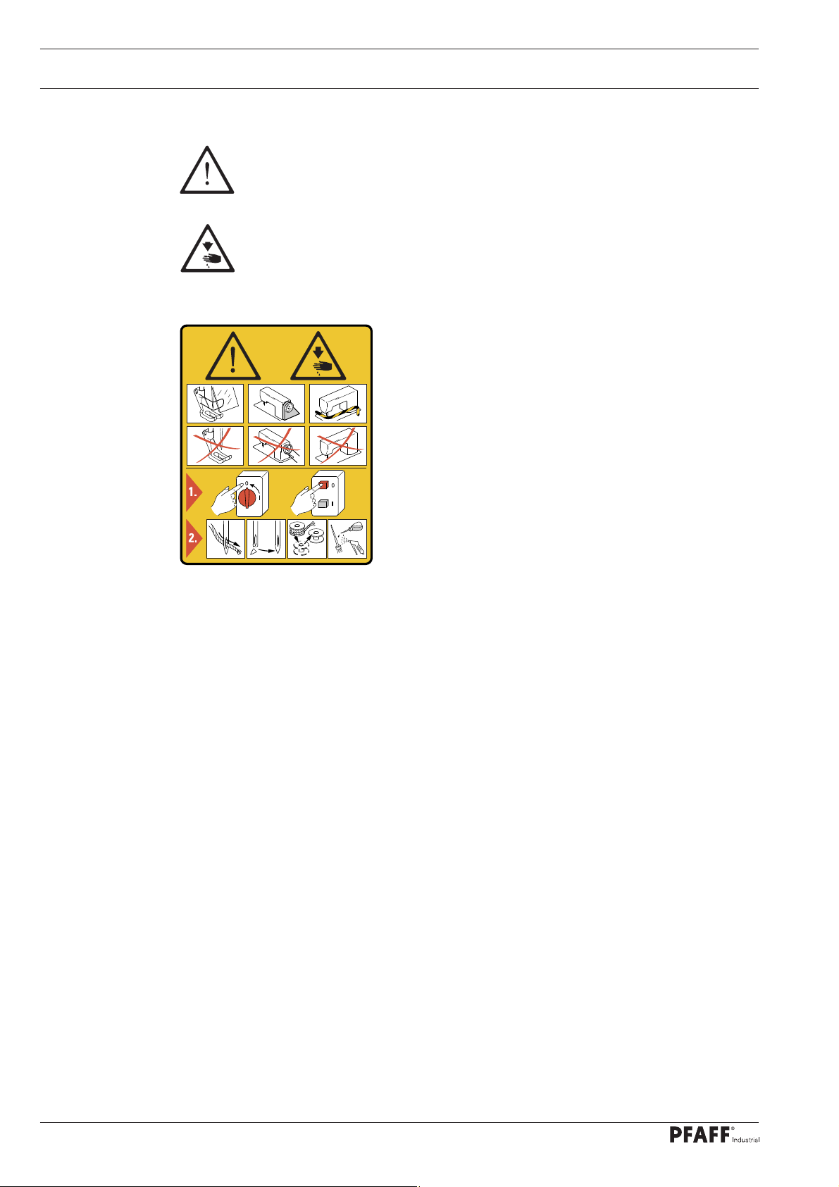
1.06 Danger warnings
A working area of 1 m must be kept free both in front of and behind
the machine, so that easy access is possible at all times.
Never put your hands in the sewing area during sewing!
Danger of injury by the needle!
While setting or adjusting the machine do not leave any objects on the table nor
in the needle plate area! Objects may be trapped or slung out of the machine!
Fig. 1 - 01
3
2
6
Only operate the machine with cover 1 closed!
Danger of injury from moving machine parts!
Do not operate the machine without fi nger guard 2!
Danger of injury from the needle!
4
1
5
Do not operate the machine without eye shield 3!
Danger of injury from needle fragments which might fl y out!
Do not place hands in the knife area 4!
Danger of injury from the knife!
Do not operate the machine without belt covers 5 and 6!
Danger of injury from the drive belts!
8
Page 9
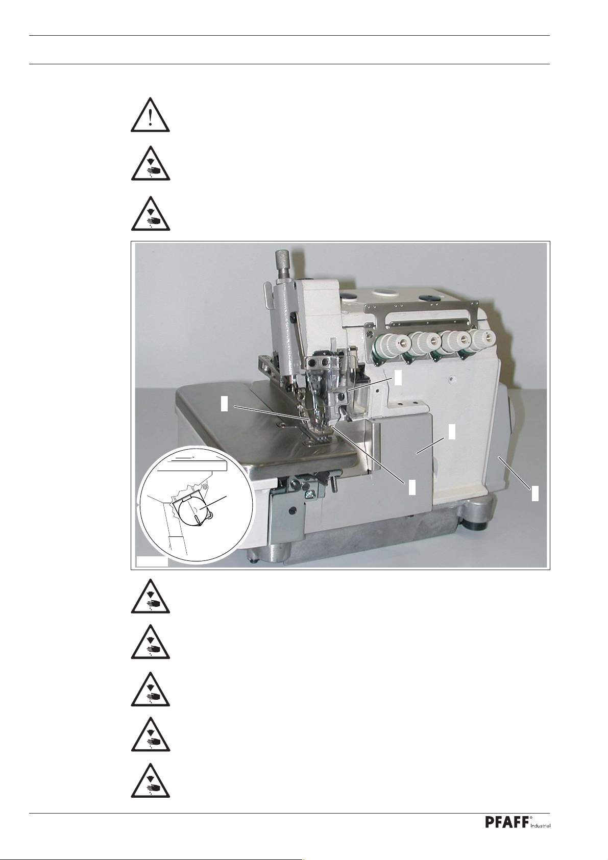
2 Proper use
The machines of the series PFAFF 6300 are single or double-needle overedge sewing
machines with stub arm and differential bottom feed.
The machines of the series PFAFF 6500 are single or double-needle overedge sewing
machines with differential bottom feed.The machines of the series
PFAFF 6700 are single or double-needle overedge sewing machines with differential top
and bottom feed.
These machines are used for producing closing and blindstitch seams.
Proper use
Any and all uses of this machine which have not been approved of by the
manufacturer are considered to be inappropriate! The manufacturer cannot be
held liable for any damage caused by the inappropriate use of the machine!
The appropriate use of the machine includes the observance of all operational,
adjustment, maintenance and repair measures required by the manufacturer!
9
Page 10

Specifi cations
3 Specifi cations▲
3
.01 General specifi cations
Stitch type: ................................................................................................................. see table
Needle system: .............................................................................................................. DCx27
Needle size: ..............................................................................................65 – 130 Nm (#9-21)
Motor data: .................................................................................see motor specifi cation plate
Noise data:
Emission sound level at workplace at a speed of 4800 spm: ....................... LpA = 80.0 dB(A)
(Noise measurement in accordance with DIN 45 635-48-B-1, ISO 11204, ISO 3744, ISO 4871)
Sewing head dimensions:
Length: ............................................................................................................approx. 300 mm
Width: .............................................................................................................. approx. 370 mm
Height: ............................................................................................................ approx. 250 mm
■
Standard base dimensions:
Length: .......................................................................................................... approx. 1060 mm
Width: .............................................................................................................. approx. 600 mm
Height: ............................................................................................................ approx. 820 mm
Net weight (sewing head): ....................................................................................approx. 29 kg
Gross weight of sewing head (with packaging): ..................................................approx. 39 kg
▲
Subject to alterations
■
KpA = 2,5 dB
10
Page 11
Specifi cations
3.02 Specifi cations of the 6504
Typ of machine
6504-01/S23-4
6504-02/S33-4
6504-32R2/S23-1,5
6504-32R2/S23-3
6504-82/S23-4
6505-12/S23-4
Number of needles
1 3 - 3; 4 3,8 5 8500 504
1 3 - 3; 4 3,8 5 8500 504
1 3 - 1,5 3,2 5 7000 504
1 3 - 1,5 3,2 5 7000 504
1 3 - 3; 4 3,8 5 8500 504
1 3 - 3; 4 3,8 5,5 8500 505
Number of threads
Number of threads
3.03 Specifi cations of the 6314, 6514, 6714
Seam width (mm)
Stitch length (mm)
Material clearance
(mm)
Max. sewing speed
(spm)
Stitch type
Typ of machine
6514-01/S34-2x4 2 4 2 3, 4, 5 3,8 5 8000 514
6514-03/M34-2x4 2 4 2 3, 4, 5 3,8 5,5 7500 514
6514-83/M34-2x4 2 4 2 3, 4, 5 3,2 5 7500 514
6714-03/M34-2x4 2 4 2 3, 4 3,8 5,5 7500 514
6314-03/M34-2x4 2 4 2 3, 4, 5 3,8 5,5 7500 514
6314T-03/M34-2x4 2 4 2 3, 4, 5 3,8 5,5 7500 514
Number of needles
Number of threads
Number of threads
Seam width (mm)
Stitch length (mm)
Material clearance
(mm)
Max. sewing speed
(spm)
Stitch type
11
Page 12

Specifi cations
3.04 Specifi cations of the 6516, 6716
Typ of machine
6516-02/S25-3x5 2 5 3 4, 5 3,8 5 7500 516
6516-03/S35-5x5 2 5 5 5, 6 3,8 5 7500 516
6716-03/S35-5x5 2 5 5 5, 6 3,8 5 7500 516
6516H-05/H35-5x6 2 5 6 5, 6 5 5 6000 516
Number of needles
3.05 Specifi cations of the 6544
Number of threads
Number of threads
Seam width (mm)
Stitch length (mm)
Material clearance
(mm)
Max. sewing speed
(spm)
Stitch type
12
Typ of machine
6544-53/M36-5x2x4 3 6 5x2 4 3,8 5,5 7000 401;
Number of needles
Number of threads
Number of threads
Seam width (mm)
Stitch length (mm)
Material clearance
(mm)
Max. sewing speed
(spm)
514
Stitch type
Page 13

Disposal of Machine
4 Disposal of Machine
● Proper disposal of the machine is the responsibility of the customer.
● The materials used for the machine are steel, aluminium, brass and various plastic
materials. The electrical equipment comprises plastic materials and copper.
● The machine is to be disposed of according to the locally valid pollution control regula-ti-
ons; if necessary, a specialist ist to be commissioned.
Care must be taken that parts soiled with lubricants are disposed of separately
according to the locally valid pollution control regulations!
13
Page 14

Transportation, packing and storage
5 Transportation, packing and storage
5
.01 Transportation to customer‘s premises
The machines are delivered completely packed.
5.02 Transportation inside the customer‘s premises
The manufacturer cannot be made liable for transportation inside the customer‘s premises
nor to other operating locations. It must be ensured that the machines are only transported
in an upright position.
5.03 Disposal of packing materials
The packing materials of this machine comprise paper, cardboard and VCE fi bre. Proper dis-
posal of the packing material is the responsibility of the customer.
5.04 Storage
If the machine is not in use, it can be stored as it is for a period of up to six months, but It
should be protected against dust and moisture.
If the machine is stored for longer periods, the individual parts, especially the surfaces of
moving parts, must be protected against corrosion, e.g. by a fi lm of oil.
14
Page 15

Explanation of symbols
6 Explanation of symbols
In this instruction manual, work to be carried out or important information is accentuated by
symbols. These symbols have the following meanings:
Note, information
Cleaning, care
Lubrication
Maintenance, repairs, adjustment, service work
(only to be carried out by technical staff)
15
Page 16

Controls
7 Controls
7
.01 On/off switch
● The power supply to the machine is swit-
ched on or off by turning switch 1.
1
Fig. 7 - 01
7.02 Pedals (on machines without automatic presser-foot)
● With the on/off switch on
0 = Machine stop
+1 = Sew
0
+1
+2
+ 2 = Raise presser foot
16
Fig. 7 - 02
Page 17

Controls
7.03 Pedal (on machines with elektronic motor)
● With the on/off switch on
0 +1
0 = Machine stop
+1 = Sew
+ 2 = Raise presser foot
-1
Fig. 7 - 03
7.04 Stop button for stitch length adjustment
● To adjust the stitch length, press stop
button 1 and turn the balance wheel 2 at
the same time.
2
1
Fig. 7 - 04
17
Page 18

Controls
7.05 Sewing foot retracting lever
● After pressing lever 1, the sewing foot 2
can be retracted.
1
Fig. 7 - 05
Before retracing the sewing
foot, raise the needle bar to its
highest position by turning the
balance wheel.
2
7.06 Cloth plate stop lever
2
Fig. 7 - 06
● After pressing lever 1, the cloth plate 2
can be retracted.
1
18
Page 19

Controls
7.07 Lever for selecting the differential feed setting
● The differential feed setting is selected
on lever 1. Loosen the nut 2 to change
the setting.
● Use the adjustment screw 3 for fi ne ad-
justment.
3
2
Fig. 7 - 07
1
7.08 Lever for top feed setting (series 6700 only)
1
● The top feed setting is selected on l
ever 1. Loosen the nut 2 to change the
setting.
● Use the adjustment screw 3 for fi ne
adjustment.
2
3
Fig. 7 - 08
19
Page 20

Controls
7.09 Adjustment screw for sewing foot pressure
● Sewing foot pressure must be set in
such a way as to ensure correct feed of
the work piece.
● The setting is adjusted on the adjustment
screw 1.
1
Fig. 7 - 09
20
Page 21

Installation and commissioning
8 Installation and commissioning
The machine must only be mounted and commissioned by qualifi ed personnel!
All relevant safety regulations are to be observed!
If the machine is delivered without a table, it must be ensured that the frame
and the table top which you intend to use can hold the weight of the machine
and the motor. It must be ensured that the supporting structure is suffi ciently
sturdy, including during all sewing operations.
8.01 Installation
The site where the machine is installed must be provided with suitable connections for the
electric current, see Chapter 3 Specifi cations.
It must also be ensured that the standing surface of the machine site is fi rm and horizontal,
and that suffi cient lighting is provided.
8.01.01 Adjusting the table-top height
1
2
Fig. 8 - 01
● Loosen screws 1 and 2 and set the desired table-top height
● Tighten screws 1 well.
1
● Adjust the position of the pedal so that you can operate it comfortably and tighten screw 2.
21
Page 22

Installation and commissioning
8.01.02 Tightening the V-belt
● Loosen nut 1.
● By swinging the motor 2, tighten the
Vbelt accordingly.
● Tighten nut 1.
Please note the instructions
in the operating manual of
the drive.
1
2
Fig. 8 - 02
.01.03 Fitting the top belt guard
8
● Attach belt guard 1 to the machine case
with the screws 2.
22
2
1
Fig. 8 - 03
Page 23

Installation and commissioning
.01.04 Mounting the bottom V-belt guard
8
● Adjust bottom -V-belt guard 1 so that the
motor pulley and V-belt run freely.
Please note the instructions
in the operating manual of
the drive.
1
Fig. 8 - 04
8.01.05 Chain for securing the pedal
1
● Secure chain 1 for raising the sewing foot
to lever 2 and to the right pedal.
Fig. 8 - 05
23
Page 24

Installation and commissioning
8.01.06 Mounting the reel stand
24
Fig. 8 - 06
● Mount the reel stand as shown in Fig. 8-06.
● Afterwards insert the stand in the hole in the table top and attach it with the nuts
provided
Page 25

Installation and commissioning
8.01.07 Connecting the plug-in connections and earth cables
1
Fig. 8 - 07
● Connect all plug connections as described in the operations manual of the drive.
● Attach ground cables for machine, main switch, control unit and motor to ground point 1.
1
8.02 Commissioning
● Check the machine, particularly its electrical wiring , for any damage.
● Clean the machine thoroughly and oil it (see chapter 10 Care and maintenance).
● Have skilled personnel check if the machine can be operated with the available mains vol-
tage.
Do not operate the machine if there is any discrepancy.
The machine may only be connected to an earthed socket!
25
Page 26

Installation and commissioning
8.03 Switching the machine on/off
● Switch the machine on (see Chapter
1
7.01, On/off switch).
● When the machine is running, the
balance wheel should turn away from the
operator.
● Carry out a test run, making sure that oil
can be seen in inspection glass 1.
Fig. 8 - 08
26
Page 27

Setting up
9 Setting up
All instructions and regulations in this instruction manual must be observed.
Special attention must be given to all safety regulations!
All setting-up work must only be done by personnel with the necessary train-
ing. For all setting-up work the machine must be isolated from its power supply
by turning off the on/off switch or removing the machine plug from the electric
power socket!
9.01 Inserting the needle / Threading the thread
1
Fig. 9 - 01
Switch the machine off!
Danger due to unintentional starting of the machine!
Only use needles from the system intended for the machine, see Chapter 3
Specifi cations.
● By turning the balance wheel, bring the needle bar to its t.d.c.
● Loosen screw 1.
3
2
● Insert the needle as far as possible.
● The long needle groove must be facing forwards.
● Tighten screw 1.
● Thread the sewing thread on the inside of the cover 2 as shown in the threading diagram.
● Adjust the relevant needle thread tension by turning milled nuts 3.
27
Page 28

Care and maintenance
10 Care and maintenance
10
.01 Maintenance intervals
Clean the machine ........................ once a day, more often when in continuous operation
Clean the hook compartment ........ once a day, more often when in continuous operation
Check the oil level ..................................................................................................... daily
Change the oil ............................... 4 weeks after commissioning, then every six months
Oil the thread lubrication .................................................................................. as required
Oil the machine ..................................... during commissioning and after long downtimes
Change the knife .............................................................................................. as required
These maintenance intervals are calculated for the average running time of a
single shift operation. If the machine is operated more than this, shorter inter-
vals are recommended.
10.02 Cleaning the machine
The cleaning cycle required for the machine depends on following factors:
● Single or several shift operation
● Amount of dust resulting from the workpiece
It is therefore only possible to stipulate the best possible cleaning instructions for each indi-
vidual case.
For all cleaning work the machine must be disconnected from the mains by
switching off the on/off switch or by disconnecting the mains plug!
Danger of injury if the machine starts accidentally!
To avoid breakdowns, the following cleaning work is recommended for single shift operation:
● Clean hook compartment and needle area several times a day.
● Clean the entire machine at least once a day.
28
Page 29

Care and maintenance
10.03 Cleaning the hook compartment
Switch off the machine!
Danger of injury if the machine
is started accidentally!
● Open the hook compartment cover 1.
● Clean the hook compartment.
● Close the cover 1.
1
Fig. 10 - 03
.04 Checking the oil level
10
● When the machine is at a standstill,
2
check whether the oil level in inspection
glass 1 is between both markings.
● If necessary, remove plug 2 and pour in
oil to the top marking.
● Replace plug 2.
1
Fig. 10 - 04
We recommend PFAFF sewing-machine oil, part
No. 280-1-120 144.
Only use oil with a viscosity of
22.0 mm2/s at 40° C and a density of 0.865 g/cm3 at 15°C!
29
Page 30

Care and maintenance
10.05 Oiling the machine
Fig. 10 - 05
Switch off the machine!
Danger of injury if the machine starts accidentally!
● Before commissioning and before operation after long downtimes, a few extra drops of
oil should be applied to the needle bar and hook bar (see arrow).
Only use oil with a viscosity of 22.0 mm2/s at 40° C and a density of 0.865 g/cm3
at 15°C!
We recommend PFAFF sewing-machine oil, part No. 280-1-120 144.
30
Page 31

Care and maintenance
10.06 Oiling the thread lubrication
2
1
Fig. 10 - 05
Switch off the machine!
Danger of injury if the machine starts accidentally!
● There must always be oil in oil tank 1 and felt pad 2.
● When required, fi ll oil into oil tank 1 or soak felt pad 2 with oil.
We recommend PFAFF thread lubricating oil, part no. 280-1-120 217.
31
Page 32

Care and maintenance
10.07 Changing the oil
2
1
Fig. 10 - 07
3
4
Fig. 10 - 07a
Switch off the machine!
Danger of injury if the machine starts accidentally!
● Place a suitable vessel in position and remove screw 1.
● Let the oil drain off completely.
● Retighten screw 1 with a new sealing ring 2.
● Remove the plug 3 to add fresh machine oil; fi ll up to the top marking on the
sight glass 4.
● Replace plug 3.
● Carry out a test run and check whether the oil in inspection glass 3 is visible.
Only use oil with a viscosity of 22.0 mm2/s at 40° C and a density of 0.865 g/cm3
at 15°C!
We recommend PFAFF sewing-machine oil, part No. 280-1-120 144.
32
Page 33

Care and maintenance
10.08 Changing the knife
1
Fig. 10 - 08
3
0,5 - 1 mm
4
5
2
0 - 0,3 mm
67
Switch off the machine!
Danger of injury if the machine starts accidentally!
Preparation
● Loosen screw 1, move knife holder 2 as far as possible to the left and slightly tighten
screw 1.
Changing the top knife
● Using the balance wheel, position knife holder 3 at t.d.c., unscrew screw 4 and remove
knife 5.
● Insert a new knife and slightly tighten screw 4.
Changing the bottom knife
● Unscrew screw 6 and remove knife 7.
● Insert new knife and slightly tighten screw 6.
Adjustment
● The knives 5 and 7 should be positioned so that
- the blade of the top knife 5 and of the bottom knife 6 overlap by 0.5 – 1.0 mm.
- the bottom knife 7 is 0.0 -0.3 mm below the needle plate and
- the knives 5 and 7 cross each other at their central points.
● Position knives 5 and 7 accordingly and tighten screws 4 and 6.
● Adjust the cutting pressure with knife holder 2 and tighten screw 1.
33
Page 34

PFAFF Industriesysteme
und Maschinen AG
Hans-Geiger-Str. 12 - IG Nord
D-67661 Kaiserslautern
Telefon: +49 - 6301 3205 - 0
Telefax: +49 - 6301 3205 - 1386
E-mail: info@pfaff-industrial.com
Gedruckt in der BRD / Printed in Germany / Imprimé en la R.F.A. / Impreso en la R.F.A
© PFAFF Industriesysteme und Maschinen AG 2009, PFAFF is the exclusive trademark of VSM Group AB.PFAFF Industriesysteme und Maschinen AG is an authorized licensee of the PFAFF trademark.
 Loading...