

Page 1

571
574
ADJUSTMENT MANUAL
591
This Adjustment Manual is valid for machines
from the following serial numbers onwards:
# 6 500 120
296-12-19 196/002
Justieranleitung engl. 07.12
Page 2

The reprinting, copying or translation of PFAFF Service Manuals, whether in whole or in part,
is only permitted with our previous authorization and with written reference to the source.
PFAFF Industriesysteme
und Maschinen AG
Hans-Geiger-Str. 12 - IG Nord
D-67661 Kaiserslautern
Page 3

Index
Contents ................................................................................ Page
1 Adjustment ........................................................................................................................... 5
1.01 Tools, gauges and other accessories .................................................................................... 5
1.02 Abbreviations ......................................................................................................................... 6
1.03 Explanation of the symbols .................................................................................................... 6
1.04 Adjusting the basic machine .................................................................................................. 7
1.04.01 Needle position in sewing direction (on the PFAFF 571 and 591) ......................................... 7
1.04.02 Needle position in sewing direction (on the PFAFF 574) ........................................................ 8
1.04.03 Preliminary adjustment of the needle height ......................................................................... 9
1.04.04 Needle rise, hook clearance, needle height and needle guard (on the PFAFF 571) .................10
1.04.05 Needle rise, hook clearance, needle height and needle guard (on the PFAFF 574) .................12
1.04.06 Needle rise, hook clearance, needle height and needle guard (on the PFAFF 591) .................14
1.04.07 Needle position crosswise to sewing direction (on the PFAFF 571) .................................... 16
1.04.08 Needle position crosswise to sewing direction (on the PFAFF 574) .................................... 17
1.04.09 Needle position crosswise to sewing direction (on the PFAFF 591) .................................... 18
1.04.10 Height and stroke of the bobbin case opener ...................................................................... 19
1.04.11 Height of the feed wheel (on the PFAFF 571) ...................................................................... 20
1.04.12 Height of the feed wheel (on the PFAFF 574) ...................................................................... 21
1.04.13 Height of the feed wheel (on the PFAFF 591) ...................................................................... 22
1.04.14 Stitch length control eccentric ............................................................................................. 23
1.04.15 Stitch length scale disk ........................................................................................................ 24
1.04.16 Shaft crank to feed wheel drive ........................................................................................... 25
1.04.17 Shaft crank to roller presser drive ........................................................................................ 26
1.04.18 Clearance between roller presser and feed wheel .............................................................. 27
1.04.19 Roller presser ....................................................................................................................... 28
1.04.20 Stitch length on stitch length scale ...................................................................................... 29
1.04.21 Synchronization of roller presser and feed wheel ................................................................ 30
1.04.22 Retainer (only on model 574) ............................................................................................... 31
1.04.23 Knee lever ............................................................................................................................ 32
1.04.24 Needle thread tension release ............................................................................................. 33
1.04.25 Thread check spring (PFAFF 571 and 591) ........................................................................... 34
1.04.26 Thread check springs (PFAFF 574)........................................................................................ 35
1.04.27 Bobbin winder ...................................................................................................................... 36
1.04.28 Pressure of roller presser .....................................................................................................37
1.04.29 Lubrication ...........................................................................................................................38
1.04.30 Re-engage safety coupling ...................................................................................................39
1.05 Adjusting the edge trimmer -725/04 .................................................................................... 40
1.05.01 Position of the knife holder (on model 571) ......................................................................... 40
1.05.02 Position of the knife holder (on models 574 and 591) .......................................................... 41
1.05.03 Knife stroke (on model 571) ................................................................................................. 42
3
Page 4

Index
Contents ................................................................................Page
1.05.04 Knife stroke (on models 574 and 591) .................................................................................. 43
1.05.05 Cutting stroke (on model 571).............................................................................................. 44
1.05.06 Cutting stroke (on models 574 and 591) .............................................................................. 45
1.05.07 Knife position ....................................................................................................................... 46
1.06 Adjusting the thread trimmer -900/83 .................................................................................. 47
1.06.01 Resting position of the roller lever / radial position of the control cam ................................ 47
1.06.02 Position of the thread catcher holder ...................................................................................48
1.06.03 Position of the thread catcher .............................................................................................. 49
1.06.04 Knife position and knife pressure ......................................................................................... 50
1.06.05 Bobbin thread retaining spring ............................................................................................. 51
1.06.06 Manual cutting test .............................................................................................................. 52
1.06.07 Releasing the tension .......................................................................................................... 53
1.06.08 Linkage rod (only for the PFAFF 574) ...................................................................................54
1.07 Adjustment of backtacking mechanism -911/.. ..................................................................... 55
1.07.01 Needle in needle hole (only for PFAFF 571 and 591) ........................................................... 55
1.07.02 Coupling for roller presser drive ........................................................................................... 56
1.07.03 Bevel gears for feed wheel drive ......................................................................................... 57
1.07.04 Bevel gear play ..................................................................................................................... 58
1.07.05 Adjusting the magnets ......................................................................................................... 59
1.08 Parameter settings ...............................................................................................................60
2 Block diagram ..................................................................................................................... 61
4
Page 5

Adjustment
1 Adjustment
Please observe all notes from Chapter 1 Safety of the instruction manual!
In particular care must be taken to see that all protective devices are refi tted
properly after adjustment, see Chapter 1.06 Danger warnings of the instruc-
tion manual!
If not otherwise stated, the machine must be disconnected from the electrical
power supply. Danger of injury due to unintentional starting of the machine!
Notes on adjustment
All following adjustments are based on a fully assembled machine and may only be carried
out by expert staff trained for this purpose.
Machine covers, which have to be removed and replaced to carry out checks and adjust-
ments, are not mentioned in the text.
The order of the following chapters corresponds to the most logical work sequence for
machines which have to be completely adjusted. If only specifi c individual work steps are
carried out, both the preceding and following chapters must be observed.
Screws, nuts indicated in brackets ( ) are fastenings for machine parts, which must be
loosened before adjustment and tightened again afterwards.
1.01 Tools, gauges and other accessories
● 1 set of screwdrivers with blade widths from 2 to 10 mm
● 1 set of open-ended wrenches with opening sizes from 7 to 13 mm
● 1 set of allen keys from 1.5 to 6 mm
● 1 clamp (Order No. 08-880 137-00)
● 1 metal rule (Order No. 08-880 218-00)
● 1 gauge (Order No. 08-880 136-01)
● Sewing thread and test material
5
Page 6

Adjustment
1.02 Abbreviations
1.03 Explanation of the symbols
TDC = top dead center
BDC = bottom dead center
In this adjustment manual, symbols emphasize operations to be carried out or important in-
formation. The symbols used have the following meaning:
Note, information
Service, repair, adjustment, maintenance
(work to be carried out by qualifi ed staff only)
6
Page 7
Adjustment
1.04 Adjusting the basic machine
1
.04.01 Needle position in sewing direction (on the PFAFF 571 and 591)
Requirement
With the stitch length set at its minimum, the needle should be positioned in the centre
of the needle hole, as seen in the direction of sewing.
1
Fig. 1 - 01
● Set the minimum stitch length.
● Adjust needle bar (screw 1) according to the requirement.
7
Page 8
Adjustment
61-078
1.04.02 Needle position in sewing direction (on the PFAFF 574)
Requirement
The needle should be positioned in the centre of the needle hole as seen in the direction
of sewing.
2
61-077
1
Fig. 1 - 02
● Adjust needle bar (screws 1 and 2) according to the requirement.
8
Page 9
Adjustment
1.04.03 Preliminary adjustment of the needle height
Requirement
When the needle bar is at TDC, there must be a clearance of approx. 21 mm between the
needle point and the needle plate.
2
1
21 mm
90-036
Fig. 1 - 03
● Adjust needle bar 1 (screw 2), without turning it, according to the requirement.
9
Page 10
Adjustment
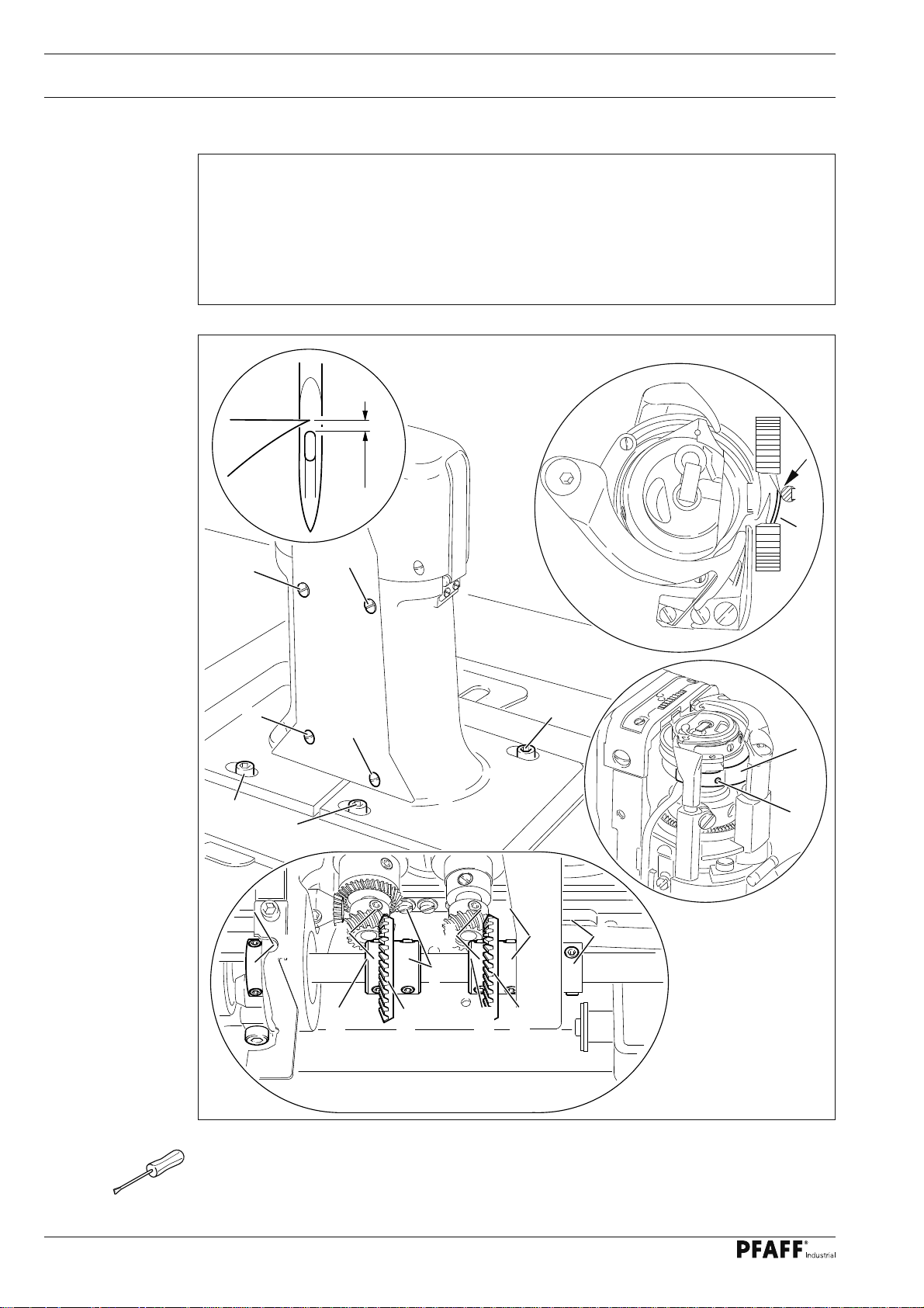
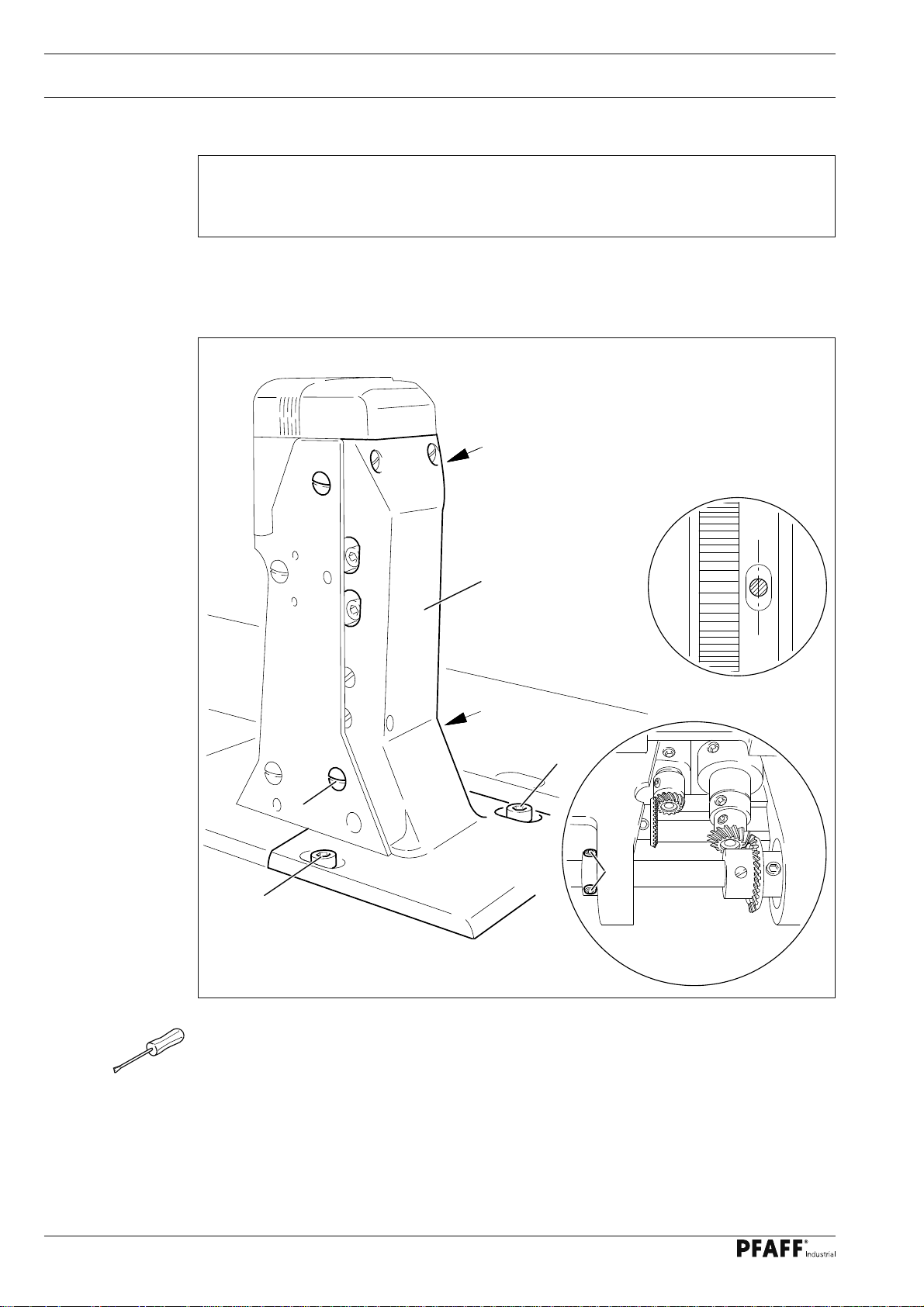
1.04.04 Needle rise, hook clearance, needle height and needle guard (on the PFAFF 571)
Requirement
With the needle bar positioned 2,4 mm after BDC and the stitch length set at "0.8"
1. the hook point must be at needle centre with a hook-to-needle clearance of
0.05 to 0.1 mm;
2. the top of the needle eye must be 0.8 to 1.0 mm below the hook point;
3. the needle guard 6 must touch the needle lightly.
6
9
2 3
7
8
1
6
4
129-002
10
5
Fig. 1 - 04
● Set stitch length at "0.8".
● Loosen both screws 1, 2, 3, 4 and 5.
● Bring needle bar to 2.4 mm past BDC:
5
61-023
0,8 - 1 mm
Page 11

Adjustment
● Set hook point at needle centre, making sure that the needle is not defl ected by needle
guard 6.
● Adjust needle height according to Requirement 2.
● Adjust hook post according to Requirement 1 and tighten screws 4 and 5.
● Making sure that there is some play in the bevel gear, tighten screws 1.
● With retaining collar 7 touching bevel gear 8 tighten screws 2 and 3.
● Adjust needle guard 6 (screw 9) according to requirement 3.
When the hook is changed, make sure that
the markings 10 and 11 are both on one side.
10
11
11
Page 12
Adjustment
1.04.05 Needle rise, hook clearance, needle height and needle guard (on the PFAFF 574)
Requirement
With the needle bar positioned 2,4 mm after BDC
1. the hook point must be at needle centre with a hook-to-needle clearance of
0.05 to 0.1 mm;
2. the top of the needle eye must be 0.8 to 1.0 mm below the hook point;
3. the needle guard 9 must touch the needle lightly.
0,8 - 1 mm
9
7
7
129-002
7
8
7
9
129-001
8
14
8
1
2
4
5
6
3
10 11
12
13
61-025
12
Fig. 1 - 05
● Loosen screws 1, 2, 3, 4, 5, 6 and 7.
● Loosen screws 8 slightly.
● Bring needle bar to 2.4 mm past BDC:
Page 13

Adjustment
● Set both hook points at needle centre, making sure that the needles are not defl ected by
needle guard 9.
● Adjust needle height according to Requirement 2.
● Adjust both hook posts according to Requirement 1 and tighten screws 8.
● Tighten screws 1 and 6.
● Making sure that there is some play in the bevel gear, tighten screws 3 and 5.
● With retaining collar 10 touching bevel gear 11 tighten screws 2.
● With retaining collar 12 touching bevel gear 13 tighten screws 4.
● Tighten screws 7 on both sides of the post.
● Adjust needle guard 9 (screw 14) on both hooks according to rRquirement 3.
When a hook is changed, make sure that
the markings 15 and 16 are both on one side.
15
16
13
Page 14
Adjustment
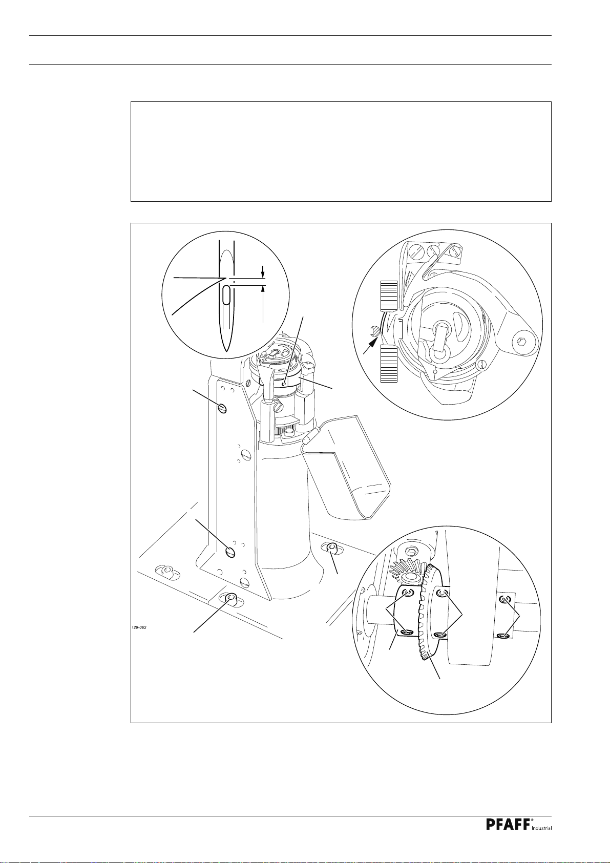
1.04.06 Needle rise, hook clearance, needle height and needle guard (on the PFAFF 591)
Requirement
With the needle bar positioned 2,4 mm after BDC
1. the hook point must be at needle centre with a hook-to-needle clearance of
0.05 to 0.1 mm;
2. the top of the needle eye must be 0.8 to 1.0 mm below the hook point;
3. the needle guard 6 must touch the needle lightly.
9
0,8 - 1 mm
5
6
129-051
5
4
1
2
3
61-028
4
7
14
8
Fig. 1 - 06
● Set stitch length at "0.8".
● Loosen screws 1, 2, 3, 4 and 5.
● Bring needle bar to 2.4 mm past BDC:
Page 15

Adjustment
● Set hook point at needle centre, making sure that the needle is not defl ected by needle
guard 6.
● Adjust needle height according to Requirement 2.
● Adjust hook post according to Requirement 1 and tighten screws 4.
● Making sure that there is some play in the bevel gear, tighten screws 2.
● With retaining collar 7 touching bevel gear 8 tighten screws 1.
● Screws 5 remain loosened for further adjustments.
● Adjust needle guard 6 (screw 9) according to Requirement 3..
When the hook is changed, make sure
that the markings 10 and 11 are both
on one side.
10
11
15
Page 16
Adjustment
1.04.07 Needle position crosswise to sewing direction (on the PFAFF 571)
Requirement
When the stitch length is set at its maximum, the needle must be positioned in the cen-
tre of the needle hole when entering and coming out of the needle plate.
2
2
1
2
2
Fig. 1 - 07
● Turn screws 1 (screws 2, on both sides of the post) according to the requirement.
61-029
16
Page 17
Adjustment
1.04.08 Needle position crosswise to sewing direction (on the PFAFF 574)
Requirement
As seen crosswise to the sewing direction, the needles must penetrate in the centre of
their needle holes.
Fig. 1 - 08
1
2
2
2
2
● Shift bearing plate 1 (screws 2, on both sides of the post) according to the requirement.
17
Page 18
Adjustment
1.04.09 Needle position crosswise to sewing direction (on the PFAFF 591)
Requirement
As seen crosswise to the sewing direction, the needle must penetrate in the centre of
the needle hole.
4
Fig. 1 - 09
1
4
2
4
90-035
3
2
18
● Adjust feed wheel post 1 (screws 2, 3 and 4) according to the requirement.
Page 19
Adjustment
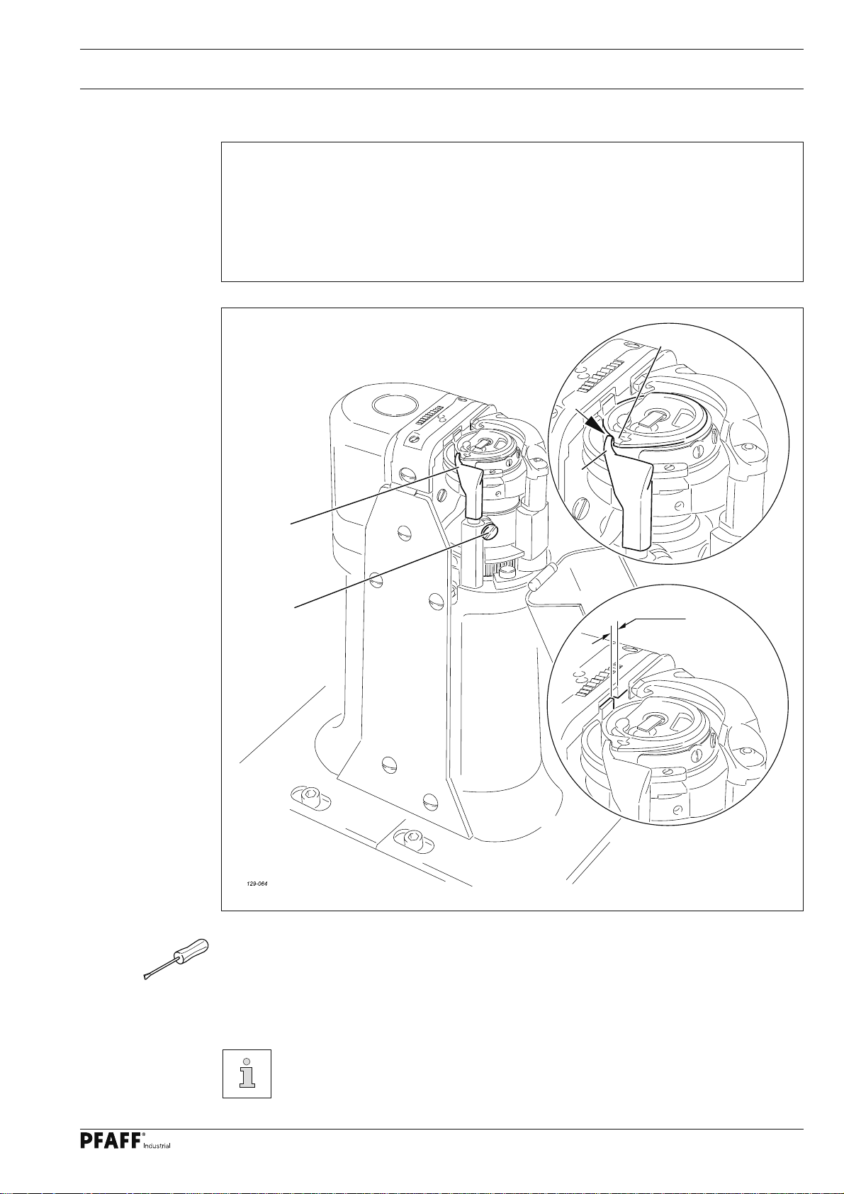
1.04.10 Height and stroke of the bobbin case opener
Requirement
1. The top edges of the bobbin case opener 1 and bobbin case base 3 should be on one
level.
2. When the bobbin case opener 1 has defl ected the bobbin case to its furthest point, the
catch of the bobbin case should be 0.3 – 0.5 mm from the back edge of the needle plate
recess.
3
129-006
1
Fig. 1 - 10
1
2
0,3 - 0,5 mm
129-007
● Adjust bobbin case opener 1 (screw 2) in accordance with requirement 1.
● Turn the balance wheel until the bobbin case opener has defl ected the bobbin case to its
furthest point.
● Adjust bobbin case opener 1 (screw 2) in accordance with requirement 2.
On the PFAFF 574 these adjustments must be repeated on the right post.
Depending on the thread size, a variation of the setting in Requirement 2 is
permitted.
19
Page 20
Adjustment
1.04.11 Height of the feed wheel (on the PFAFF 571)
Requirement
1. When pressure is applied to the feed wheel 4, it should protrude from the needle plate
by tooth height (approx. 0.8 mm)
2. When no pressure is applied to the feed wheel 4 , it should have a vertical play of ap-
prox. 0.3 mm.
4
0,8 mm
Fig. 1 - 11
0,3 mm
1
5
2
1
3
20
● Swing out the roller presser.
● Loosen screws 1 and 2.
● Adjust drive wheel 3 according to requirement 1, taking care to see that the teeth of
drive wheel 3 and feed wheel 4 lock into each other properly.
● Tighten screws 1.
● Adjust guide 5 according to requirement 2 and tighten screws 2.
Page 21

Adjustment
1.04.12 Height of the feed wheel (on the PFAFF 574)
Requirement
1. When pressure is applied to the feed wheel 4, it should protrude from the needle plate
by tooth height (approx. 0.8 mm)
2. When no pressure is applied to the feed wheel 4 , it should have a vertical play of ap-
prox. 0.3 mm.
4
0,8 mm
Fig. 1 - 12
0,3 mm
2
1
5
1
3
● Swing out the roller presser.
● Loosen screws 1 and 2 (two screws each).
● Adjust drive wheel 3 according to requirement 1, taking care to see that the teeth of
drive wheel 3 and feed wheel 4 lock into each other properly.
● Tighten screws 1.
● Adjust guide 5 according to requirement 2 and tighten screws 2.
21
Page 22

Adjustment
1.04.13 Height of the feed wheel (on the PFAFF 591)
Requirement
The feed wheel should protrude from the needle plate by tooth height (approx. 0.8 mm)
61-039
0,8 mm
1
3
Fig. 1 - 13
2
● Swing out the roller presser.
● Loosen screws 1.
● Adjust eccentric 3 (fastening screw accessible through hole 2) according to the require-
ment.
● Tighten screws 1.
61-035
22
Page 23

Adjustment
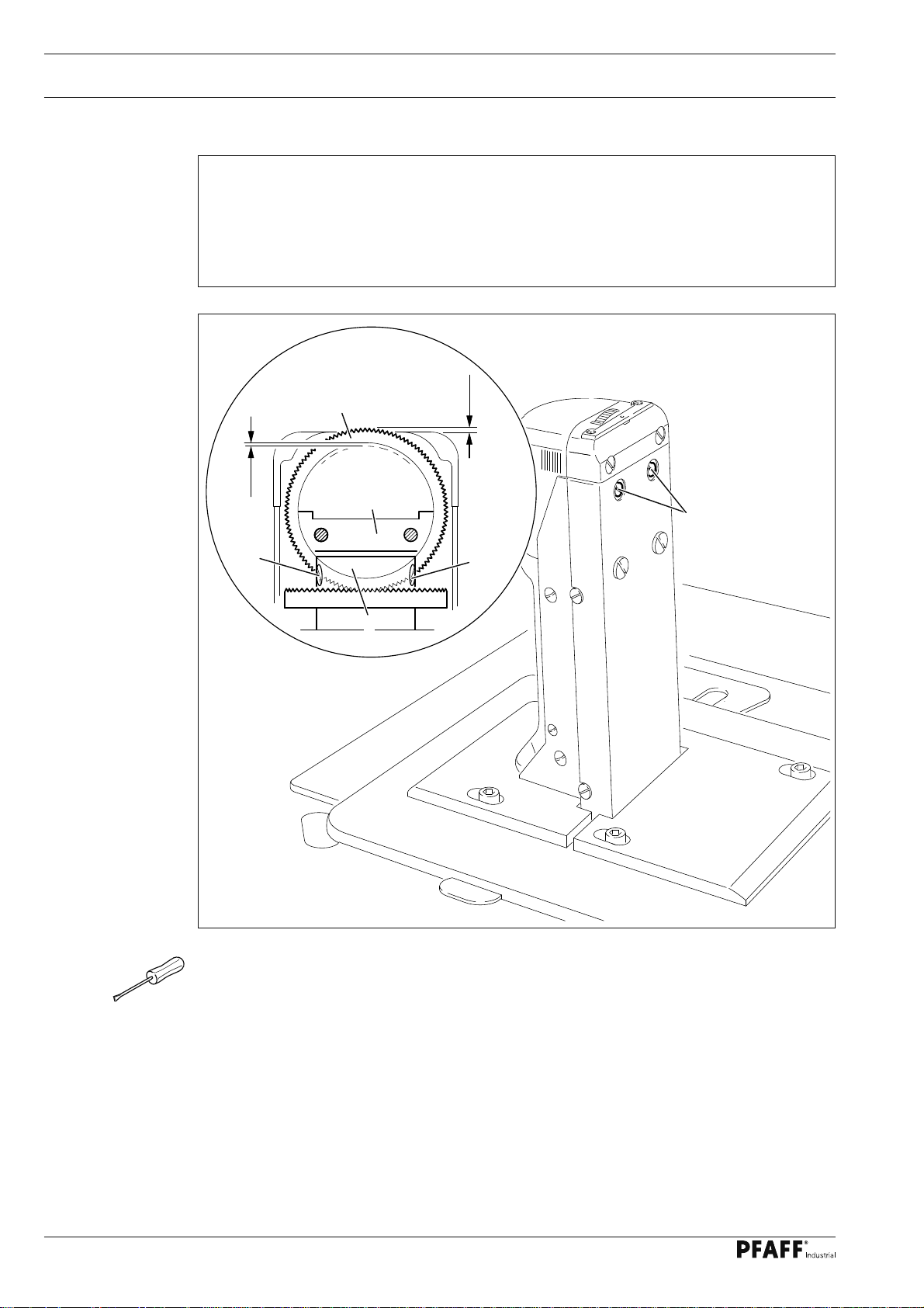
1.04.14 Stitch length control eccentric
Requirement
When the needle (with maximum stitch length set), coming from TDC, is 3 mm above the
needle plate, the crank 3 must have reached its front point of reversal.
1
2
2
3
Fig. 1 - 14
● Set the maximum stitch length.
● lTurn stitch length control device 1 (screws 2) according to the requirement.
23
Page 24

Adjustment
1.04.15 Stitch length scale disk
Requirement
When the stitch length control device is engaged and the stitch length is set at “0”, the
marking line on scale disk 1 should be positioned opposite the lower edge 3 of the guard
belt opening.
3
2
Fig. 1 - 15
● Set stitch length "0".
● Turn stitch length control device 1 (screws 2) according to the requirement.
61-038
1
24
Page 25
Adjustment
1.04.16 Shaft crank to feed wheel drive
Requirement
When the maximum stitch length is set, the linkage rod 3, or linkage rods 3 and 4 on the
models 571 and 591, must be able to move freely when the balance wheel is turned.
PFAFF 571
PFAFF 591
3
4
2
1
3
2
1
Fig. 1 - 16
● Set the maximum stitch length.
● Twist or shift the shaft crank 1 (screw 2) according to the requirement.
PFAFF 574
25
Page 26

Adjustment
1.04.17 Shaft crank to roller presser drive
Requirement
When the maximum stitch length is set, the linkage rods 3 and 4 must be able to move
freely at their left and right point of reversal when the balance wheel is turned.
3
1
2
4
Fig. 1 - 17
● Set the maximum stitch length.
● Twist clamp crank 1 (screw 2) according to the requirement.
26
Page 27

Adjustment
1.04.18 Clearance between roller presser and feed wheel
Requirement
When the presser bar lifter is raised, the clearance between the roller presser and the
feed wheel must be 7 mm.
2
1
Fig. 1 - 18
● Raise the presser bar lifter.
● Adjust the presser bar 1 (screws 2) according to the requirement. Make sure that the
roller presser is parallel to the feed wheel.
7 mm
61-040
27
Page 28

Adjustment
1.04.19 Roller presser
Requirement
When the roller presser 1 is touching the feed wheel 5 it must
1. be parallel to feed wheel 5, as seen in the direction of sewing,
2. be in the centre of the needle (on model 574 the left needle), as seen in the direction
of sewing,
3. be as near as possible to the needle (on model 574 the left needle), as seen crosswise
to the direction of sewing.
4
5
3
1
Fig. 1 - 19
● Raise the roller presser.
● Always observe requirement 1 for subsequent adjustments.
● Adjust roller presser 1 (screw 2) according to requirement 2.
● Lower roller presser 1 to rest on feed wheel 5.
2
28
● Adjust roller presser bracket 3 (screw 4) according to requirement 3.
When sewing very tight curves, the roller presser 1 must be moved a little to-
wards the operator.
Page 29

Adjustment
1.04.20 Stitch length on stitch length scale
Requirement
When the stitch length is set at "3", and after the needle has entered a strip of leather 11
times, the total length from the fi rst to last needle penetration must be 30 mm.
PFAFF 571
PFAFF 591
Fig. 1 - 20
2
1
2
1
2
PFAFF 574
● Set stitch length "3".
● By turning the balance wheel, let the needle enter 11 times and measure the total length.
● Adjust clamp 1 (screw 2) according to the requirement.
Clamp 1 must not be positioned diagonally to the rock shaft!
29
Page 30

Adjustment
1.04.21 Synchronization of roller presser and feed wheel
Requirement
After 30 needle penetrations in a strip of leather the total length from the fi rst to the last
penetration should be the same, both in the lower and the upper leather layer.
2
2
1
Fig. 1 - 21
● Set stitch length "3".
● By turning the balance wheel, let the needle enter 30 times.
● Compare the total sewn length of the lower and upper leather layer.
● Adjust clamp 1 (screw 2) according to the requirement.
30
Clamp 1 must not be positioned diagonally to the rock shaft.
Page 31

Adjustment
1.04.22 Retainer (only on model 574)
Requirement
The retainer 1 must
1. be as close as possible to the needle, as seen in the direction of sewing and
2. be in the centre of the needle, as seen crosswise to the direction of sewing.
3. When the roller presser is lowered, the distance between the retainer 1 and the work-
piece must be 0.2 - 0.3 mm.
2
1
Fig. 1 - 22
● Adjust retainer 1 (screw 2) according to requirement 3.
● Adjust bracket 3 (screw 4) according to requirement 1 and 2.
3
4
129-010
31
Page 32

Adjustment
61-079
1.04.23 Knee lever
Requirement
1. Before the roller presser rises, the knee lever must still have a slight play.
2. When the knee lever is raised as far as possible, the lever for the roller presser must
drop automatically.
3. Knee lever bar 5 must be at an angle of approx. 75° to the bedplate.
5
75°
6
4
3
Fig. 1 - 23
● Adjust screw 1 (nut 2) according to requirement 3.
● Adjust screw 3 (nut 4) according to requirement 2.
● Set bar 5 (Screws 6) according to requirement 3.
2
1
32
Page 33

Adjustment
1.04.24 Needle thread tension release
Requirement
1. When the presser bar lifter is raised, the tension discs 3 should be pressed at least
0.5 mm apart.
2. When the roller presser is lowered, the tension must be fully effective.
0,5 mm
3
1
2
61-043
Fig. 1 - 24
● Align tension mounting plate 1 and pressure plate 2 according to the requirement.
33
Page 34

Adjustment
1.04.25 Thread check spring (PFAFF 571 and 591)
Requirement
1. The movement of thread check spring 7 should be completed when the needle point
penetrates the fabric (spring stroke approx. 7 mm).
2. When the largest thread loop is formed while the thread is passed around the hook,
the thread check spring 7 should rise slightly from its support
4
61-046
5
7 mm
6
1
7
3
Fig. 1 - 25
● Adjust support 1 (screw 2) according to requirement 1.
● To adjust the spring tension turn screw 3 (screw 4).
● Adjust the thread regulator 5 (screw 6) according to requirement 2.
For technical reasons it may be necessary to deviate from the specifi ed spring
stroke or spring tension.
Move the thread regulator 5 (screw 6) towards "+" (= more thread) or "-" (= less
thread).
2
34
Page 35

Adjustment
1.04.26 Thread check springs (PFAFF 574)
Requirement
1. The movement of thread check springs 3 and 6 should be completed when the need-
le points penetrate the fabric (spring stroke approx. 7 mm).
2. When the largest thread loop is formed while the thread is passed around the hook,
the thread check springs 3 and 6 should rise slightly from supports 1 and 9.
5
61-046
11 12
7 mm
3
1
8
6
2
9
4
10
Fig. 1 - 26
● Adjust support 1 (screw 2) according to requirement 1.
● To adjust the spring tension of thread check spring 3 turn screw 4 (screw 5).
● To adjust the spring tension of thread check spring 6 turn bush 7 (screw 8).
● Adjust support 9 (screw 10) according to requirement 1. (If the adjustment range is too
low, support 9 can be screwed into another hole).
7
● Adjust the thread regulator 11 (screw 12) according to requirement 2.
For technical reasons it may be necessary to deviate from the specifi ed spring
stroke or spring tension.
Move the thread regulator 11 (screw 12) towards "+" (= more thread) or "-" (=
less thread).
35
Page 36

Adjustment
1.04.27 Bobbin winder
Requirement
1. When the bobbin winder is engaged, the winding spindle must be driven reliably.
When the bobbin winder is disengaged, the friction wheel 5 must not be moved by
drive wheel 1.
2. The bobbin winder must switch itself off, when the fi lled thread is about 1 mm from
the edge of the bobbin.
1
5
2
61-047
4
3
36
Fig. 1 - 27
● Position drive wheel 1 (screws 2) according to requirement 1.
● Position bolt 3 (screw 4) according to requirement 2.
Page 37

Adjustment
1.04.28 Pressure of roller presser
Requirement
The material must be fed smoothly. No pressure marks should be visible on the material.
1
Fig. 1 - 28
● Adjust roller presser pressure with screw 1 according to the requirement.
37
Page 38

Adjustment
1.04.29 Lubrication
Requirement
After a running time of 10 seconds a fi ne line of oil should form on a strip of paper held
next to the hook.
1
129-011
Fig. 1 - 29
● Check whether oil has been fi lled in and that there is no air in the oil lines.
● Let the machine run for 2-3 min.
While the machine is running do not place hands in the needle or hook area!
Danger of injury from moving parts!
● With the machine running hold a strip of paper on the hook and check the requirement.
● If necessary, adjust the oil fl ow on screw 1.
38
Page 39
Adjustment
1.04.30 Re-engage safety coupling
The coupling 1 is set by the manufacturer. When the thread jams, the coupling
1 disengages in order to avoid damage to the hooks.
A description of how to engage the coupling follows.
1
2
Fig. 1 - 30
● Remove jammed thread.
● Hold coupling 1 with screw 2 and turn the balance wheel, until you feel coupling 1
snap back into place again.
129-012
39
Page 40

Adjustment
1.05 Adjusting the edge trimmer -725/04
1
.05.01 Position of the knife holder (on model 571)
Requirement
When the thread trimmer is engaged and the adjusting wheel has been turned to its high-
est position
1. the knife holder 2 must be parallel to the post and
2. the top edge of the needle plate must be in the centre of the angular knife opening.
2
61-051
3
1
Fig. 1 - 31
● Turn the adjusting wheel 1 to its highest position and engage edge trimmer.
● Adjust knife holder 2 (screw 3) according to the requirements.
61-050
40
Page 41

Adjustment
1.05.02 Position of the knife holder (on models 574 and 591)
Requirement
When the thread trimmer is engaged, the centre of the angular knife opening must be le-
vel with the top edge of the needle plate.
2
3
1
4
61-052
Fig. 1 - 32
● Switch off the machine and engage the edge trimmer.
● Loosen screw 1.
● By turning sccentric 2, position the knife in the centre of its adjustment range.
● Adjust knife holder 3 according to the requirement and tighten screw 1.
● Position locking ring 4 on the knife holder 3.
Depending on the material thickness, changes in the basic setting of
eccentric 2 are possible.
41
Page 42

Adjustment
1.05.03 Knife stroke (on model 571)
Requirement
The knife stroke can be adjusted over a range from 1.0 to 3.5 mm, allowing the best
possible adaption to all materials used.
3
1
2
2
3,5
3,5
42
Fig. 1 - 33
● Turn eccentric 1 (screws 2) so that the marking of the desired cutting stroke is opposite
the marking on clamp collar 3.
Page 43

Adjustment
1.05.04 Knife stroke (on models 574 and 591)
Requirement
The knife stroke can be adjusted over a range from 2.0 to 3.5 mm, allowing the best
possible adaption to all materials used.
1
2
Fig. 1 - 34
● Adjust crank 1 (nut 2) in slotted lever 3 according to the requirement.
3
43
Page 44

Adjustment
1.05.05 Cutting stroke (on model 571)
Requirement
When the edge trimmer is engaged and the needle is in the needle hole, the stroke of
knife 1 should be half in front of and half behind the needle, when the motor shaft is tur-
ned by hand.
1
1
2
1/2
1/2
44
Fig. 1 - 35
● Switch off the machine and engage the edge trimmer.
● Adjust knife 1 (screw 2) according to the requirement.
Page 45

Adjustment
1.05.06 Cutting stroke (on models 574 and 591)
Requirement
When the edge trimmer is engaged and the needle is in the needle hole, the stroke of
knife 3 should be half in front of and half behind the needle, when the motor shaft is tur-
ned by hand.
3
1/2
1/2
2
1
Fig. 1 - 36
● Switch off the machine and engage the edge trimmer.
● Adjust knife holder 1 (screw 2) according to the requirement.
61-052
45
Page 46

Adjustment
1.05.07 Knife position
Requirement
When the edge trimmer is engaged, the knife should rest lightly on the needle plate in-
sert, but no whistling sound should occur during trimming.
3
4
2
61-055
1
Fig. 1 - 37
PFAFF 571
● Adjust screw 1 (screw 2) according to the requirements.
46
● Carry out a cutting test and repeat adjustment if necessary.
PFAFF 574 und 591
● Adjust knife 3 (screw 4) according to the requirements.
● Carry out a cutting test and repeat adjustment if necessary.
Page 47

Adjustment
1.06 Adjusting the thread trimmer -900/83
1
.06.01 Resting position of the roller lever / radial position of the control cam
Requirement
1. When the thread trimmer is in is resting position, lever 5 should be touching piston 6
and the roller of roller lever 7 should be 0.3 mm away from control cam 3.
2. When the take-up lever is at t.d.c., control cam 3 should just have placed roller lever 7
in its resting position.
7
0,3 mm
9
4
8
3
1
Fig. 1 - 38
● Having made sure that piston 6 is positioned against the left stop, adjust magnet 1 (2
screws) in accordance with requirement 1.
6 5
10
● Adjust control cam 3 (screws 4) in accordance with requirement 2.
● Attach collar 8 (screw 9) to roller 10.
47
Page 48

Adjustment
1.06.02 Position of the thread catcher holder
Requirement
1. There should be a minimum amount of play between toothed wheel 3 and toothed
segment 4.
2. Both in the neutral position and the foremost position of the catcher, the distance bet-
ween the toothed segment 4 and the outer edge of the thread catcher holder 1 should
be the same (see arrow).
1
4
3
1
129-015
4
1
2
4
Fig. 1 - 39
● Adjust the thread catcher holder 1 (screws 2) according to the requirements.
If requirement 2 cannot be fulfi lled, loosen screw 2 and move the toothed
segment 4 by one tooth.
2
48
Page 49

Adjustment
1.06.03 Position of the thread catcher
Requirement
1. The bottom edge of the thread catcher 1 should be at a distance of 0.1 mm from the
positioning fi nger of the bobbin case 5.
2. When the thread trimmer is in its resting position, the front edge of thread catcher 1
should be fl ush with the edge of knife 6.
6
1
0,1 mm
5
5
1
129-017
3
1
86-044
129-019
4
2
Fig. 1 - 40
● Move thread catcher 1 (screws 2, two screws) in accordance with requirement 1.
● Turn thread catcher 1 (screw 3) in accordance with requirement 2.
Thread catcher 1 must be parallel to the surface of the thread catcher holder 4.
49
Page 50

Adjustment
1.06.04 Knife position and knife pressure
Requirement
The knife pressure should be set as low as possible but the cutting operation should still
be carried out reliably.
50
1
2
129-050
Fig. 1 - 41
● Adjust eccentric 1 (screw 2) in accordance with the requirement.
129-020
Page 51

Adjustment
1.06.05 Bobbin thread retaining spring
Requirement
The tension of the bobbin thread clamp spring should be as low as possible, but it should
reliably hold the bobbin thread after trimming.
3
2
1
129-060
Fig. 1 - 42
● Adjust bobbin thread clamp spring 1 (screws 2) in accordance with requirement.
Control
● After the thread has been cut, sew a few stitches by turning the balance wheel, checking
whether the bobbin thread is drawn out of the bobbin thread clamp spring between the
1st and 3rd stitches. If necessary, correct the tension.
129-021
51
Page 52

Adjustment
1.06.06 Manual cutting test
Requirement
1. When thread catcher 1 is on its forward stroke, it must not carry bobbin thread 3 for-
ward too.
2. When thread catcher 1 is in its front position, bobbin thread 3 must be held reliably by
hook 4.
3. After the trimming action, both the needle thread and the bobbin thread must be
perfectly cut and bobbin thread 3 retained.
3
2
1
52
3
Fig. 1 - 43
● Sew a few stitches.
● Turn off the on/off switch.
● Carry out the cutting operation manually.
● Check requirement 1 and 2, and if necessary readjust thread catcher 1 in accordance
with Chapter 1.06.03 Position of the thread catcher.
● Check requirement 3, and if necessary readjust the bobbin thread retaining spring 2 in
accordance with Chapter 1.06.05 Bobbin thread retaining spring.
4
61-108
Page 53

Adjustment
1.06.07 Releasing the tension
Requirement
When the magnet is activated, tension discs 3 must be at least 0.5 mm apart.
0,5 mm
3
1
2
61-043
Fig. 1 - 44
● Activate the magnet.
● Detach the tension bearing plate 1 and adjust pressure plate 2 in accordance with the re-
quirement.
It is possible to set the time for releasing the tension with the parameter
functions, see Chapter 1.08 Parameter settings.
53
Page 54

Adjustment
1.06.08 Linkage rod (only for the PFAFF 574)
Requirement
When the thread trimmer is in its resting position, the drive levers 1 must be parallel.
1
2
Fig. 1 - 45
● Adjust drive levers 1 (screws 2) in accordance with the requirement.
1
54
Page 55

Adjustment
1.07 Adjustment of backtacking mechanism -911/..
1
.07.01 Needle in needle hole (only for PFAFF 571 and 591)
Requirement
When the maximum stitch length is set, the needle must be the same distance from the
inside edge of the needle hole, both for forward and reverse stitch.
2
1
Fig. 1 - 46
● Turn crank 1 (screws 2) according to the requirement.
55
Page 56

Adjustment
1.07.02 Coupling for roller presser drive
Requirement
1. When the roller foot is touching the feed wheel and the magnets are extended, the
top coupling half 1 should be touching the bottom coupling half.
2. There must be a distance of 3 mm between coupling half 1 and locking disc 3 of the
drive mechanism.
2
3
1
Fig. 1 - 47
● Adjust coupling half 1 (screw 2) according to the requirement.
3 mm
56
Page 57

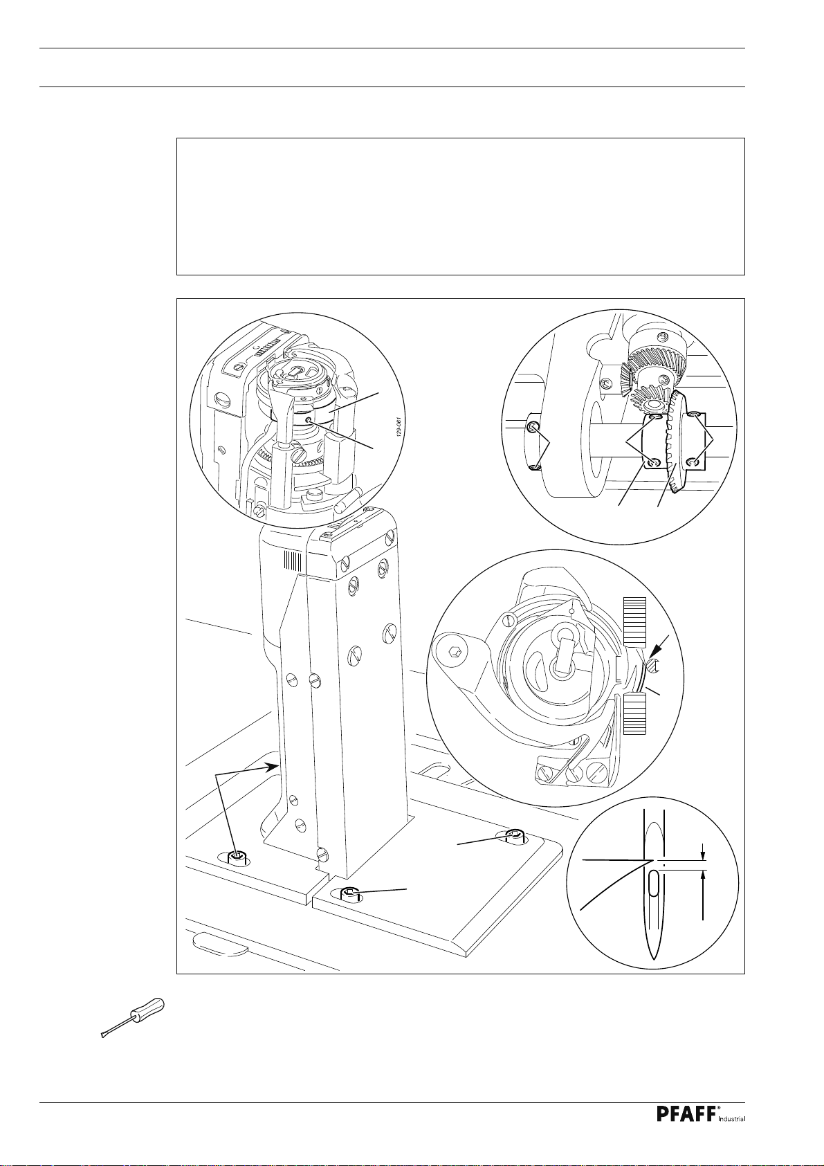
Adjustment
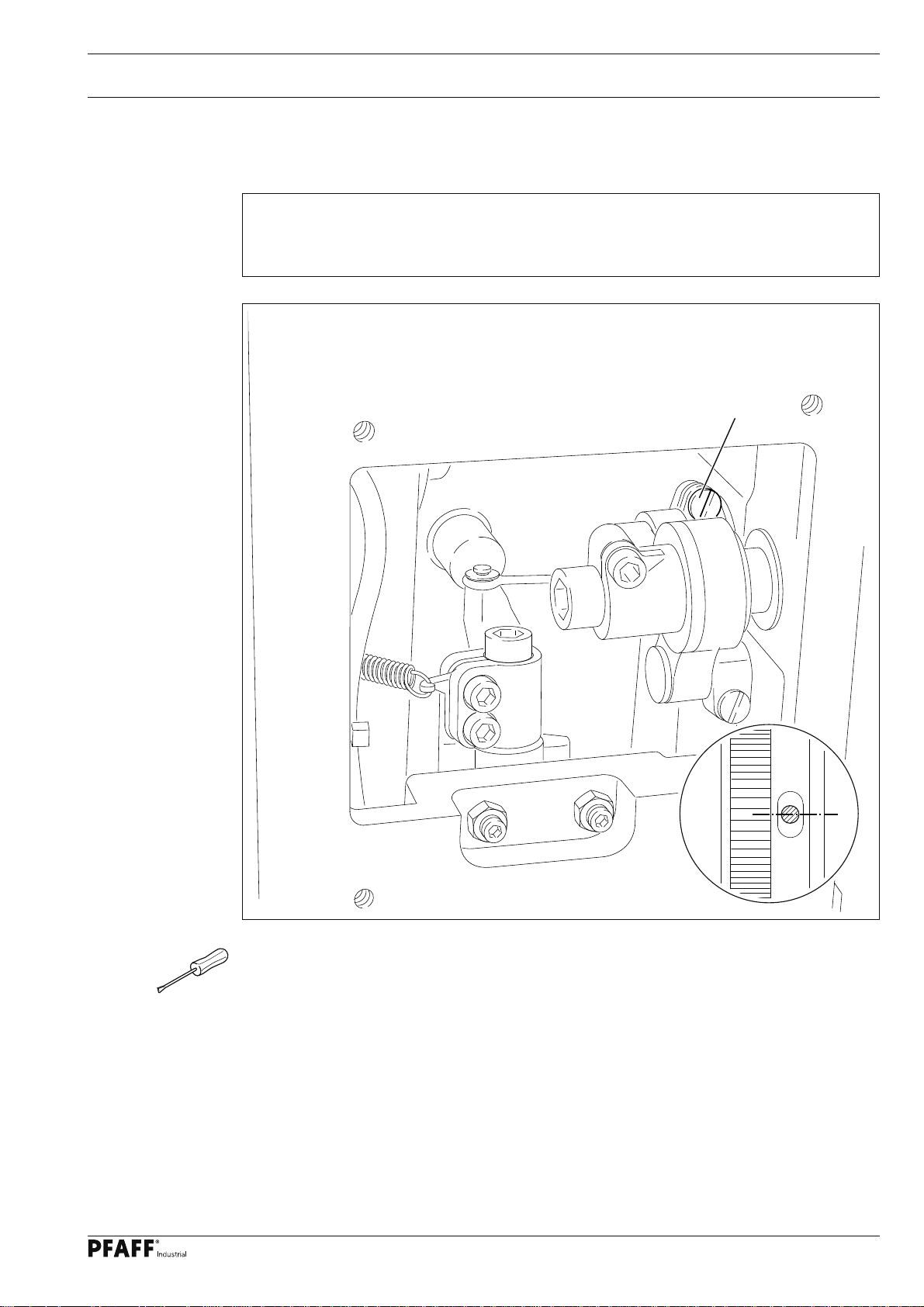
1.07.03 Bevel gears for feed wheel drive
Requirement
1. Bevel gear 3 must fi t well on the left side.
2. There must be a distance of 15 mm between bevel gear 3 and bevel gear 5.
15 mm
2
2
3
5
6
4
1
2
Fig. 1 - 48
● Remove control unit 1 (screws 2).
● Adjust bevel gear 3 (screws 4) according to requirement 1.
● Adjust bevel gear 5 (screws 6) according to requirement 2.
The cogs of bevel gears 3 and 5 must be aligned.
57
Page 58

Adjustment
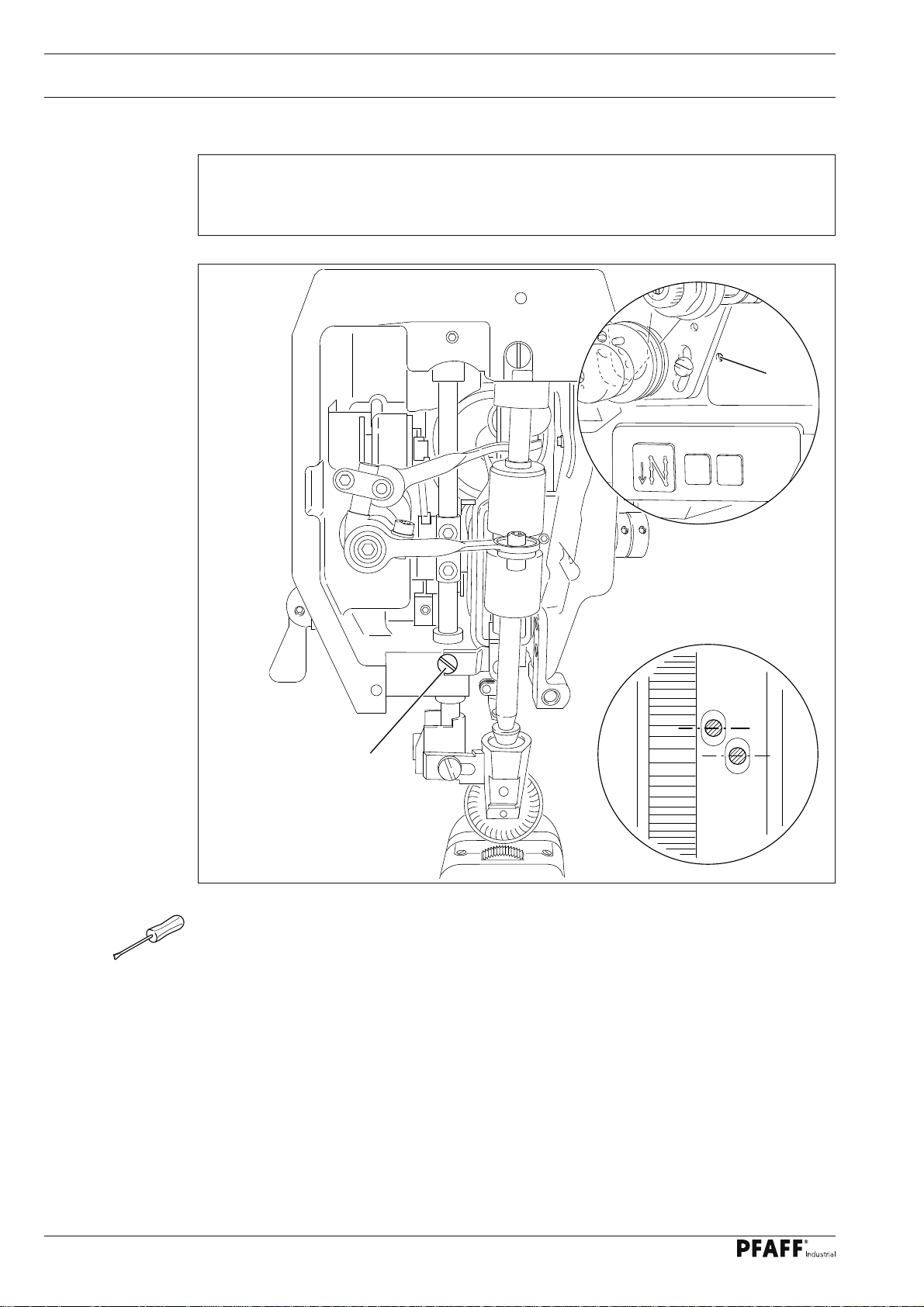
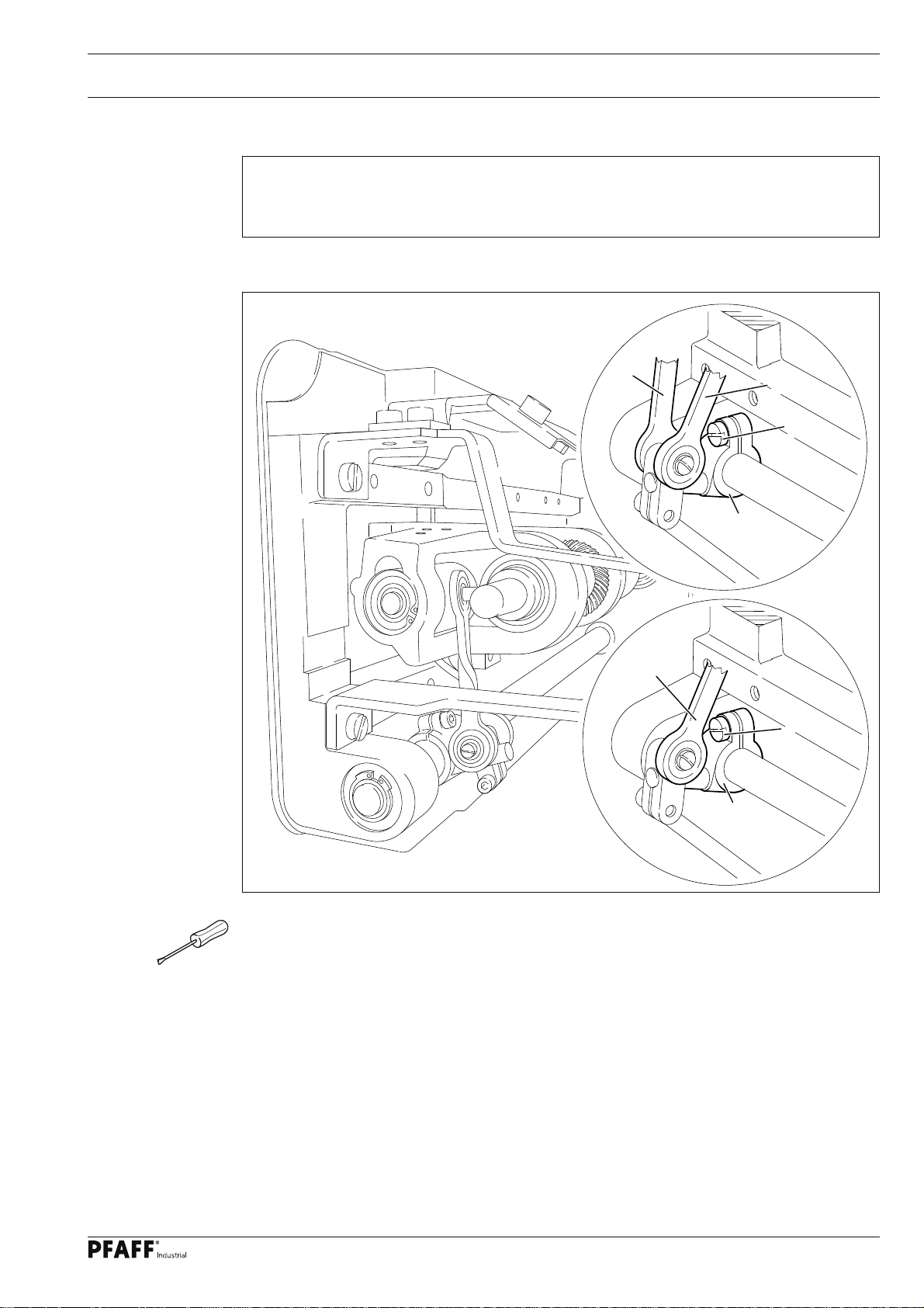
1.07.04 Bevel gear play
Requirement
1. When sewing forwards, there must be a slight play between bevel gears 6 and 7.
2. When sewing backwards, there must be a slight play between bevel gears 6 and 8.
3. The clearance between bevel gear 6 and the shaft 10 must be 0,2 mm.
1
Fig. 1 - 49
2
2
10
8
9
7
0,2 mm
6
5
4
3
58
● Adjust bracket 1 (screws 2) according to requirement 1.
● Move unit 3 by hand as far as possible to the left.
● Adjust screw 4 (nut 5) according to requirement 2.
● Bevel gear 6 ( screws 9 ) according to requirement 3 .
Page 59

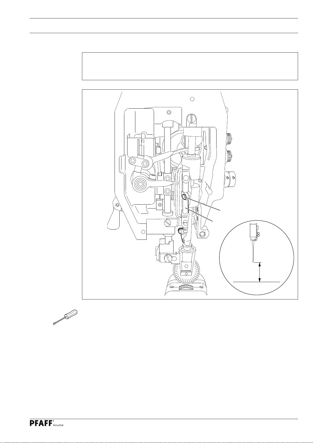
Adjustment
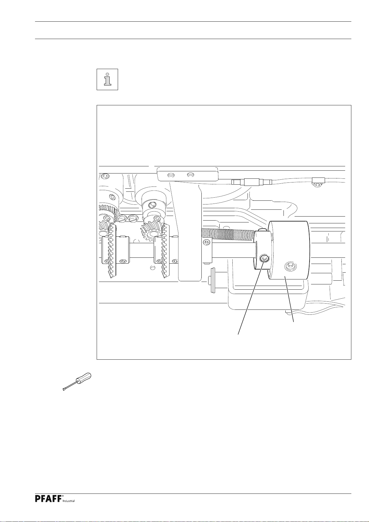
1.07.05 Adjusting the magnets
Requirement
When switch unit 1 is in its left stop position
1. The magnet frame 2 should be positioned at the top stop position and
2. The magnet tappet 4 should be completely extended.
3. When the magnet tappet 4 is extended, there should be no play between the magnet
tappet and lever 5.
4
21
5
Fig. 1 - 51
● Manually slide switch unit 1 as far as possible to the left (see arrow).
● Adjust magnet frame 2 (screws 3) in accordance with the requirements.
3
3
59
Page 60

Adjustment
1.08 Parameter settings
● Parameter settings are described in the separate operations manual for
the drive, and may only be changed by qualifi ed technicians!
60
Page 61

Version 04.02.08 Block diagram
2 Block diagram
2
.01 PFAFF 570 / 590 with control unit P44 PD-L
570/590
Synchronizer PD3
only on the 574
BDF - PICO TOP
Speedcontrolunit
Control unit P44 PD-L
PC
Drive / Ministop long
incremental transducer
for
software
download
power switch
Control package P44 PD-L
LS = Light barrier
VR1 = Roller presser release
VR2 = Feed switch-over
VR3 = VR3 – magnet (needle) only on the 571 + 591
FSL = Thread tension release
PFA = Automatic presser foot lift
-900 = Thread trimmer
STOP = Start inhibitor
Mains plug
61
Page 62

Block diagram
2.02 PFAFF 570 / 590 with MD-4-57-220-CE
VR1
VR2
FSL
-900
VR3
570 / 590
PFA
Control panel
C-200-1.0
STOP
Speedcontrolunit
Control unit MD-4-57-220-CE
VR1 = Roller presser release
VR2 = Feed switch-over
VR3 = VR3 – magnet (needle) only on the 571 + 591
FSL = Thread tension release
PFA = Automatic presser foot lift
-900 = Thread trimmer
STOP = Start inhibitor
power switch
Mains plug
62
Page 63

Block diagram
2.03 PFAFF 570 / 590 with MJ-0-00-215-CE
Synchronizer
570 / 590
Control uni MJ-0-00-215-CE
power switch
Mains plug
63
Page 64

PFAFF Industriesysteme
und Maschinen AG
Hans-Geiger-Str. 12 - IG Nord
D-67661 Kaiserslautern
Phone: +49 - 6301 3205 - 0
Fax: +49 - 6301 3205 1386
E-mail: info@pfaff-industrial.com
Hotlines:
Technical service: +49 - 175/2243-101
Application consultance: +49 - 175/2243-102
Spare-parts hotline: +49 - 175/2243-103
Printed in Germany
© PFAFF Industriesysteme und Maschinen AG 2009, PFAFF is the exclusive trademark of VSM Group AB.PFAFF Industriesysteme und Maschinen AG is an authorized licensee of the PFAFF trademark.
 Loading...