

Page 1
PFAFF
5642
Service
Manual
296-12-13925
Justieranl.
engi.
7.92
Page 2
Notesonsafety
•
The
machine
operatedbypersons
•
The
machine
•
Useofthe
•
When
bobbin)
must
be isolated from
mains
On
mechanically
the
motor
• General servicing work
• Repairs, conversion
or
persons
• For
service
compressed
Exceptionstothis
technicians.
• Work on
appropriately
must
must
machine
gauge
part
during
threading,
plug.
has
stopped.
with
appropriate
or repair work on
air
supply
the
electrical
trained
onlybecommissioned
with
appropriate
onlybeused
without
are
exchanged
the
operated
must
and
special
for
the
safety
when
the
mains by switching off
clutch
motors
onlybecarried
maintenance
training.
pneumatic
system.
are
only
adjustments
equipment
persons.
in full
training.
the
purpose
devices
(e.g.
needle,
workplace
knowledgeofthe
intended.
belonging
presser
is left,
and
the
without
systems
and
start
out
by appropriately trained
work
must
the
function
checks
must only be carried
to it is
foot,
during
not
needle
service
instruction
permitted.
plate,
work,
book
feed
the
main switch or disconnecting
inhibitor it is
necessary
to wait until
persons.
only be carried
machine
made
out
by electrical
outbytechnicians
mustbeisolated
by appropriatelytrained
engineers
and
dog
and
machine
the
from
the
• Work on parts and systems under electric current are not permitted, except as specified
in
regulations
• Conversions or
adherencetoall
• For repairs, only
Please
note:
This service manual
Divergencies in
DIN
57105orVDE 0105.
changestothe
safety
regulations.
replacement
applies
the
illustrations have no bearing on
machine must be authorized by us and only be made on
parts
approved
for
the
single-needle-aswell as for
by us
the
must
be used.
adjustments.
the
multi-needle version.
or
Tools,
gauges
Setofscrewdrivers
Set
of alien
and
other
with
keys
from 1.5to6 mm
equipment
blades
from2to10mm
needed
for
Adjustment pin, 3 mm dia. (flattened to 2.3 mm at
Positioning pin, 5 mm dia.,
Positioning pin, 6 mm, with 3 mm end dia.,
C-clamp,
Adjusting
Metal
Packetofsystem
Sewing
part
gauge(5and
rule,
part
thread
No.
08-880137-00
No.
5640
and
part
7 mm),
08-880218-00
needles
testing
fabric
No.
13-030341-05
part
No. 61-111643-54
part
adjustment
one
end), part No. 61-111643-55
No. 61-111643-53
Page 3
Contents
Notesonsafety
The
most
important
1 Preliminary
2
Looper
3
Feed
Spreader
4
5
Feed
6
Feed
6.1
Crosswisetosewing
6.2Insewing
7
Feed
8
Positionofneedleinneedle
8.1
Crosswisetosewing
8.2Insewing
9
Looper-to-needle
sewing
9.1 In
9.2
Crosswisetosewing
10
Needle
11
Spreader
11.1 In
sewing
adjustmentofneedle
drive
lifting
eccentric
drive
driving
dog
position
direction
dog
height
direction
direction
bar
height
position
direction
11.2 Crosswise to sewing direction
12
Needle
guard
13
14
15
16
17
18
Regulating
Needle
Stitch
Fabric
Knee
Tension
thread
length
clearance
lever
release
the
rest
eccentric
eccentric
eccentric
clearance
looper
regulation
limitation
position
adjustment
and
needle
direction
direction
direction
thread
and
and
data
hole
and
take-up
stroke
In brief 4
bar
height
bar
frame
drive
looper
lever
guard
limitation
Page
2
6
7
9
10
11
12
12
13
14
15
15
16
17
17
18
19
20
20
21
22
23
24
25
26
28
29
Page 4
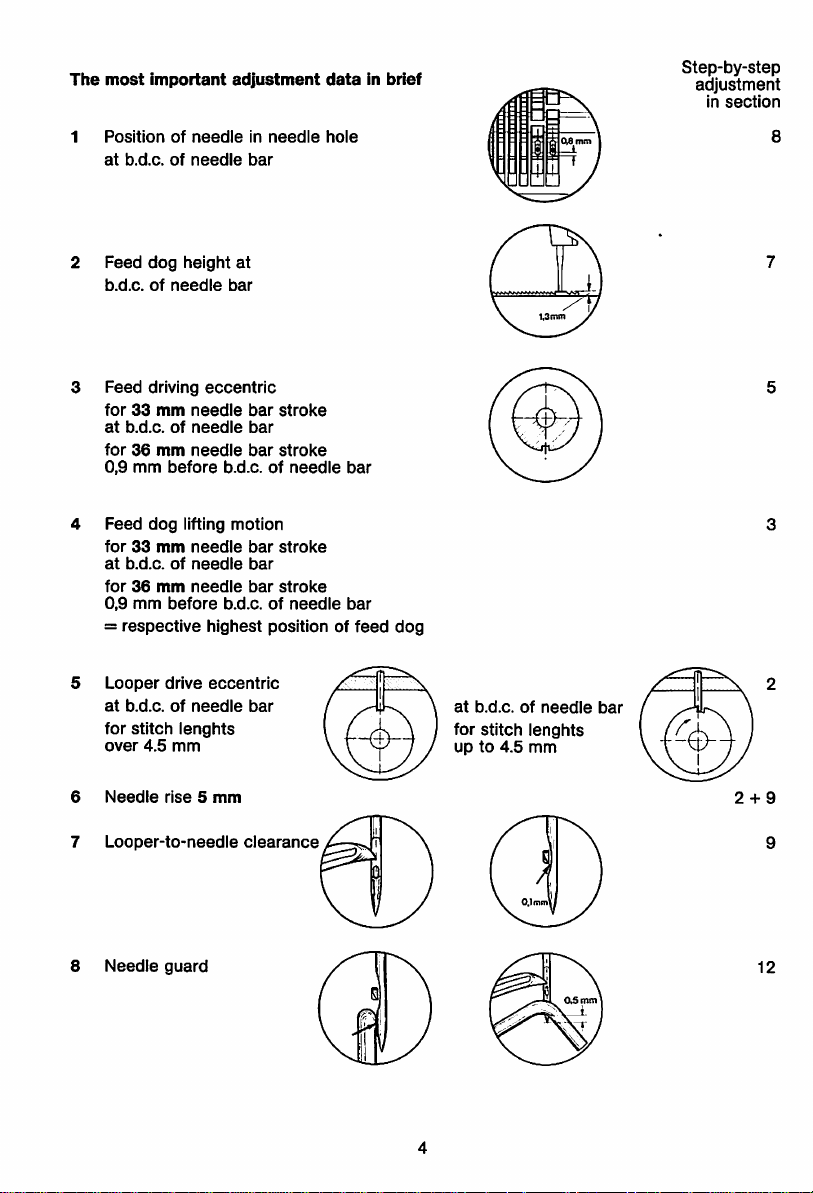
The
most
1
Position
at
Feed
b.d.c.ofneedle
Feed
for33mm
at
for36mm
0,9
Feed
for33mm
at
for36mm
0,9
=
important
of
needle
b.d.c.ofneedle
dog
height
driving
eccentric
mm
mm
dog
needle
needle
before
lifting
needle
needle
before
b.d.c.ofneedle
b.d.c.ofneedle
respective
adjustment
in
needle
bar
at
bar
bar
stroke
bar
bar
stroke
b.d.c.ofneedle
motion
bar
stroke
bar
bar
stroke
b.d.c.ofneedle
highest
positionoffeed
dataInbrief
hole
bar
bar
dog
Step-by-step
adjustment
In
section
8
Looper
at
b.d.c.ofneedle
for
stitch
over
6
Needle
7
Looper-to-needie
8
Needle
drive
4.5
mm
rise5mm
guard
eccentric
lenghts
bar
clearance
at
b.d.c.ofneedle
for
stitch
upto4.5
bar
lenghts
mm
2 + 9
12
Page 5
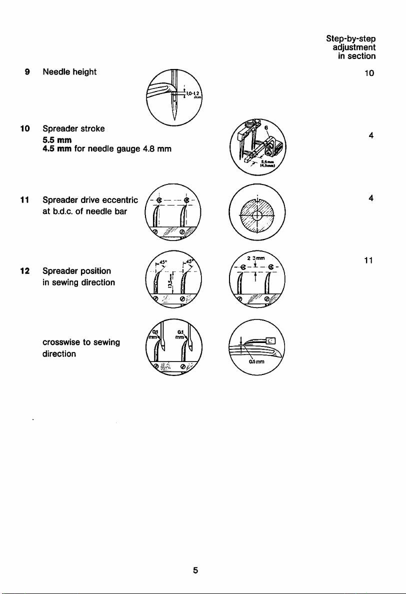
9
10
11
12
Needle
height
Spreader
5.5
mm
4.5mmfor
Spreader
at
b.d.c.ofneedle
Spreader
in
sewing
stroke
needle
drive
eccentric
position
direction
gauge
bar
4.8
mm
(4,5aMl)
Step-by-step
adjustment
in
section
10
11
crosswisetosewing
direction
Page 6
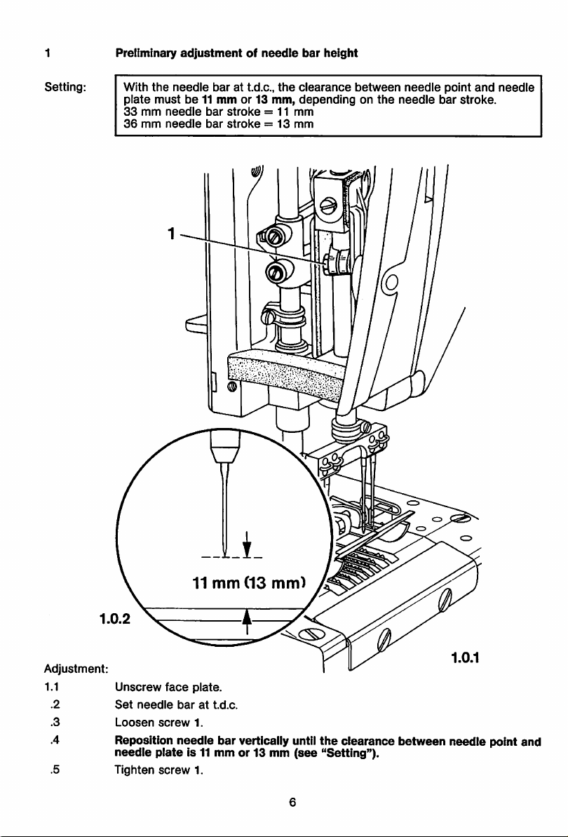
Preliminary
adjustmentofneedle
bar
height
Setting:
With
the
plate
33
36
needle
mustbe11mmor 13
mm
needle
mm
needle
bar
at t.d.c.,
bar
stroke
bar
stroke=13
j ^
the
clearance
mm,
dependingonthe
= 11
mm
mm
between
needle
needle
point
bar
and
stroke.
needle
Adjustment:
1.0.2
Unscrew
Set
Loosen
Reposition
needle
Tighten
needle
plate
face
plate.
barattd.c.
screw
1.
needle
bar
is 11 mmor13 mm
screw
1.
vertically until
(see
the
clearance
"Setting").
between
needle
point
and
Page 7
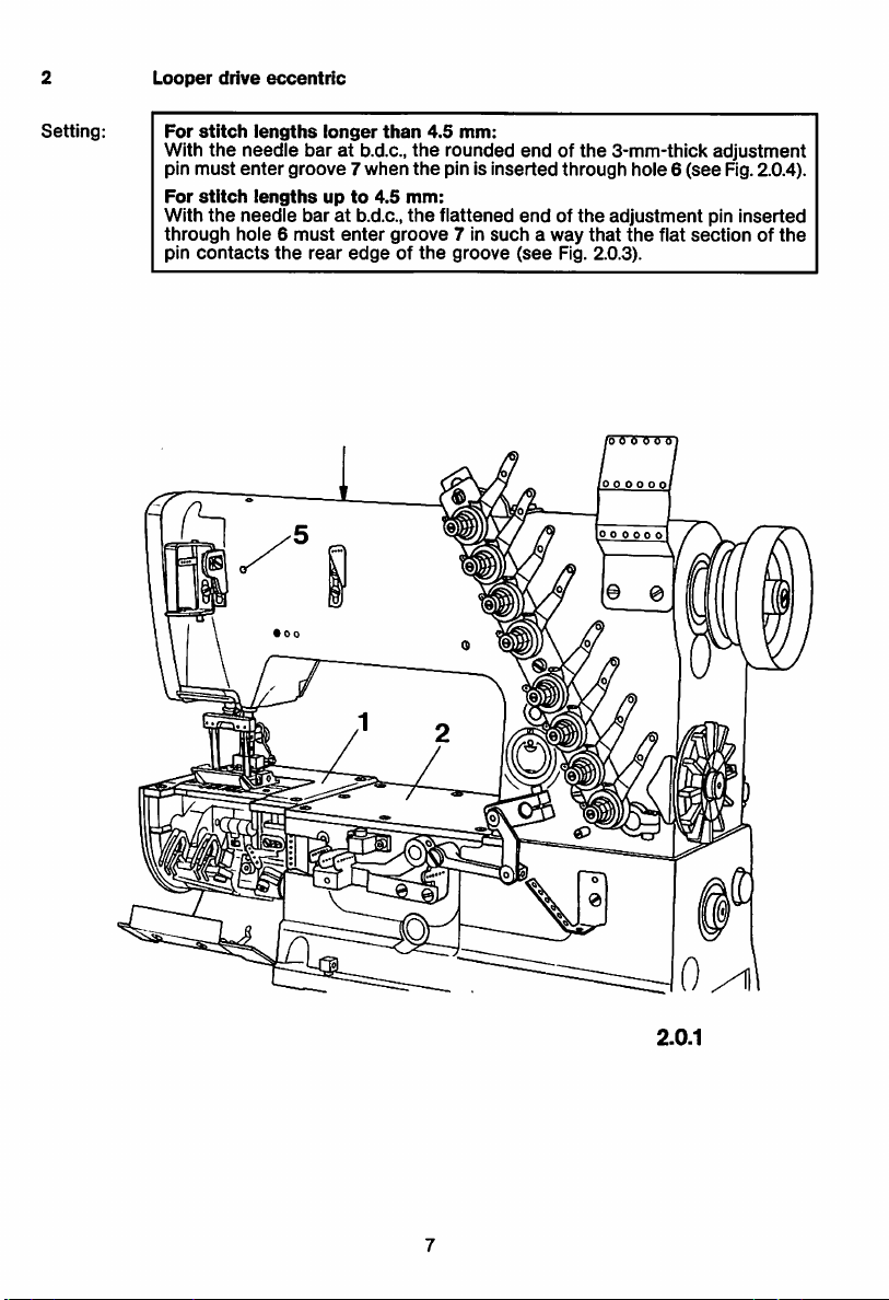
2
Looper
drive
eccentric
Setting:
For
stitch
With
pin
must
For
stitch
With
the
through
pin
contacts
lengths
the
needle
enter
lengthsupto
needle
hole6must
longer
baratb.d.c.,
groove
baratb.d.c.,
the
rear
than
7 when
4.5
mm:
the
enter
groove
edgeofthe
4.5
mm:
the
rounded
the
pin is insertedthrough hole6
flattened
groove
7 in
suchaway
endofthe
endofthe
(see
Fig. 2.0.3).
that
3-mm-thlck
(see
adjustment
the
flat
o o O O O O
adjustment
Rg. 2.0.4).
pin
inserted
sectionofthe
2.0.1
Page 8
2.0.3
2.0.4
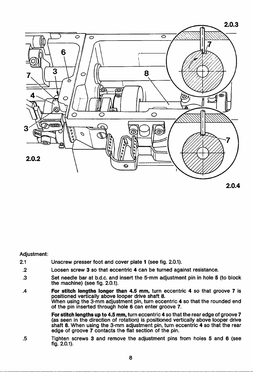
Adjustment:
2.1
.2
.3
Unscrew
Loosen
Set
the
For
positioned
When
of
For
(as
shaft8.When
edgeofgroove7contacts
Tighten
fig. 2.0.1).
presser
screw3so
needle
machine)
stitch
using
the
pin
inserted
stitch
lengthsupto
seeninthe
screws3and
foot
and
that
baratb.d.c.
(see
fig. 2.0.1).
lengths
vertically
the
longer
3-mm
above
adjustment
through
directionofrotation)ispositioned
using
the
cover
plate1(see
eccentric4canbeturned
and
insert
the
than
4.5
looper
mm,
drive
pin,
hole6can
4.5
mm,
turn
eccentric4so
3-mm
adjustment
the
flat
sectionofthe
remove
the
8
adjustment
fig. 2.0.1).
5-mm
adjustment
turn
shaft
turn
eccentric4so
enter
groove
pin,
8.
against
eccentric4so
resistance.
pin in
that
7.
that
the
rear
vertically
turn
eccentric4so
pin.
pins
from
hole5(to
that
the
groove
rounded
block
7 is
end
edgeofgroove
above
looper
drive
that
the
rear
holes5and6(see
7
Page 9
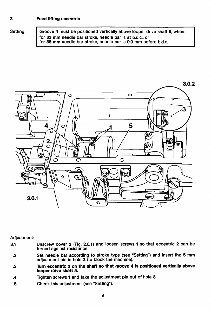
3
Feed
tiffing
eccentric
Setting:
Groove4mustbepositioned
for33mm
for36mm
needle
needle
bar
bar
stroke,
stroke,
vertically
needle
needle
above
barisat
baris0.9
looper
b.d.c.,
mm
drive
or
before
shaft5,when:
b.d.c.
3.0.2
Adjustment:
3.1
.2
Unscrew
turned
Set
adjustment
.3 Turn
looper
.4 Tighten
.5
Check
cover
against
needle
2 (Fig. 2.0.1)
resistance.
bar
accordingtostroke
pin In
eccentric2on
drive
shaft
screws1and
this
adjustment
hole
the
5.
take
and
3 (to
block
shaftsothat
the
adjustment
(see
"Setting").
loosen
type
the
screws1so
(see
machine).
groove4is
pin
out
that
"Setting")
positioned
of hole 3.
eccentric2can
and
Insert
the
vertically
be
5 mm
airave
Page 10

4
Spreader
drive
eccentric
Setting:
4.0.2
With
the
vertically
The
needle
4.8
needle
above
strokeofspreader
gauge,orneedle
mmiscontained,
baratb.d.c.,
looper
drive
bracket6mustbe5.5
gauge
this
stroke
groove
shaft
4 of
5.
combinationsinwhich
mustbe4.5
eccentric2mustbepositioned
mm.Onmachines
mm.
the
needle
with
4.8
gauge
mm
of
Adjustment:
4.1
.2
.3
.4
Loosen
Set
the
Tum
looper
Reposition
(4.5
.5 Tighten
.6
.7 Fit
Check
screws1so
needle
bar
machine).
eccentric2on
drive
shaft
eccentric
mm)
(see
screws1and
this
adjustment
the
covertothe
that
at b.d.c.
the
5.
2 axlallysothat
"Setting").
take
gear
eccentric2canbeturned
and
insert
the
5-mm
adjustment
shaftsothat
the
adjustment
(see
"Setting").
case.
groove
the
strokeofspreader
pin
10
against
4 Is
positioned
outofhole
resistance.
pin in hole 3 (to block
vertically
bracket
6 Is
above
5.5
mm
3.
Page 11

5
Feed
driving
eccentric
and
needle
bar
frame
drive
Setting: Groove 4 of
when:
for33mm
for36mm
5.0.2
feed
needle
needle
driving
bar
bar
eccentric
stroke,
stroke,
2 must be positioned exactly
needle
needle
barisat
baris0.9
b.d.c.,
mm
before
above
shaft 5,
or
b.d.c.
5.0.1
Adjustment:
5.1
.2
.3
Unscrew
Loosen
Set
the
screws1so
needle
adjustment
Turn
feed
at)ove
Tighten
Loosen
housing
linesofdrive
Fig. 5.0.3).
Tighten
Check
Replace
driving
the
center
screws
screws6and,
(see
screws6and
this
gear
gear
coveratthe
that
bar
accordingtostroke
pin in
hole
3 (to block
eccentric2on
of
shaft
1.
arrow
making
in Fig. 8.0.3),
crank8and
take
adjustment
(see
cover.
undersideofthe
eccentric2canbeturned
type
(see
"Setting")
connecting
crank8so
rod7are
pin
outofhole
its
5.
sure
tum
connecting
the
adjustment
the
machine).
shaftsothat
that
drive
"Setting").
11
machine
stand.
against
and
groove
4 is
rod7does
that
the
paralleltoeach
3.
resistance.
insert
positioned
not
imaginary
the
exactly
contact
other
5-mm
the
center
(see
Page 12

6
6.1
Feed
dog
position
Crosswisetosewing
direction
Setting:
The
them.
feed
dog
mustbecenteredInthe
needle
plate
slots
and
move
freely In
Adjustment:
6.1.1
.2
.3
.4
.5
.7
Unscrew
Loosen
Set
Fit
Position
feed
the
cover
slots.
cover
plateatthe
screws
1, 2, 3,
maximum
plate
together
feed
mechanism7so
Push fixing collars 5
and
4.
Check
this
adjustment
stitch
and
and
length.
with
6 up
(see
4.
backofthe
needle
plate.
that
against
"Setting").
12
arm-bed.
the
feed
feed
mechanism7and
dog
is laterally
centeredinthe
tighten
screws
3
Page 13

6.2
In
sewing
direction
Setting: With
hole4with
for33mm
for36mm
6.0.5
the
maximum stitch length
Its
3-mm
end,
needle
bar
needle
bar
when:
stroke,
stroke,
set,
needle
needle
the
6-mm
barIsat
barIs0.9
adjustment
b.d.c.,
or
mm
before
pin
b.d.c.
must
fit Into
6.0.3
Adjustment:
6.2.1
.2
.3
.4
.5
Set
the
type
(see
Insert
insert
that
the
Tighten
Check
maximum
stitch
"Setting").
the
5-mm
adjustment
the
6-mm
3-mm
adjustment
endofthe
screws5and6,and
this
adjustment
0
length
and
position
pin In
hole
1 (to
pininhoie2,repositioning
adjustment
(see
take
"Setting").
the
13
pin
adjustment
fits
the
block
needle
into
bar
accordingtostroke
the
machine).
connecting
hoie
4.
pins
outofholes1and
pin3so
2.
Page 14

Feed
dog
7
height
Setting:
7.0.2
With
the
the
front
(see
Fig. 7.0.3).
When
position
needle
teethofthe
using
the
contact
baratbottom
feed
dog
adjustment
the
gauge
dead
must
gauge,
(see
center
protrude
the
Fig. 7.0.4).
and
the
maximum
from
the
teethofthe
3
mm
needle
feed
stitch
length
plateby1.3
dog
mustinthis
3
mm
set,
mm
7.0.4
Adjustment:
7.1
.2
.3
.4
.6
.7
.8
.9
.10
.11
Unscrew
Loosen
Set
Loosen
stitch
Set
the
Tighten
Tighten regulating
teethofthe
plate
(The inclination of
Remove
the
cover
plate
and
the
needle
plate.
nut 1
and
turn
out
regulating
needle bar at t.d.c., push locking lever 3 to
screw4,replace
length.
cover
plate
screw
2 by 2 to 3 turns.
the
and
needle
left and swing out
plate,
and
set
the
the
loopers.
maximum
needle bar at b.d.c. and Insert the 5-mm adjustment pin in hole 5 (to block
machine).
screw4Just
feed
by 1.3 mm or,
cover
lightly.
screw2through
dog
(as
when
the
feed
plate
and
needle
seeninfeeding
the
using
gauge
dog
results from this
plate.
hole In
the
direction)
needle
protrude
No. 61-111643-37,
procedure.)
plate
from
contact
until
the
the
the
needle
gauge.
front
Lock regulating screw 2 with nut 1, tighten screw 4, and take the 5-mm adjust
ment
pin
Replace
Check
outofhole
cover
this
adjustment
plate
5.
and
needle
(see
plate
"Setting").
14
and
fix
them
with
the
screws.
Page 15

8
Position
of
needleinneedle
hole
8.1
Setting:
Crosswisetosewing
Crosswisetothe
in
the
center
(see
ti
direction
sewing
dash-dot
direction,
the
line in Fig. 8.0.4).
needles
must
enter
0 6 6 6 6 6)
000000
© ©
the
needle
holes
Adjustment:
8.1.1
.2
.3
.4
.5
.6
8.0.1
Insert
new
Loosen
Turn
Make
needle
Adjust
are
cutout,
Tighten
screws1(see
the
balance
sure
holes
the
exactly
adjustitaccordingly.
screws
(system
5640)
arrows
wheeltoset
that
the
needles
(as
seeninfeed
needle
bar
framesothat,
centeredinthe
1.
needles
in Figs. 8.0.1
the
are
the
direction);
needle
15
(the
long
groove
and
8.0.2)
needles
same
just
distance
adjust
crosswisetothe
holes,ifthe
must
and
above
from
the
needle
take-up
facetothe
screw3(see
the
needle
the
front
holder,ifnecessary.
feed
direction,
lever
strikes
8.0.2
right).
Fig. 8.0.3).
holes.
edgesofthe
the
needles
against
its
Page 16

8.2
In
sewing
direction
Setting:
With
the
the
needles
needle
and
baratb.d.c.,
the
front
edgesofthe
there
mustbea
needle
distanceof0.8
holes.
O o <9
mm
8.0.3
between
8.0.4
Adjustment:
8.2.1
Set the needle bar at b.d.c. and insert the 5-mm adjustment pin In hole 2 (to
block
the
machine).
Unscrew
Loosen
is a distanceof 0.8 mm
holes
Tighten
Check
the
coveratthe
screw3and
(Fig. 8.0.4).
screw3and
this
adjustment
backofthe
position
between
take
the
(see
machine.
the
needle
the
needles
adjustment pin
"Setting").
barinsewing
and
the
out
of hole 2.
directionsothat
front
edgesofthe
there
needle
Page 17

9
9.1
Looper-to-needle
In
sewing
direction
clearance
.Setting:
Requirement:
9.0.2
Ata needle bar position 5.0mm past
tioned
exactlyatthe
Theloopers mustbe inserted
needle
center
fully
b.d.c.,
lines.
the looper points must be posi
inthe guide slotof the looper
the looper drive eccentric must be adjusted according to chapter 2.
0
o
holders
and
Adjustment:
9.1.1
.2
.3
Remove cover plate with needle plate and unscrew
Set
needle
barata position 5.0 mm
Adjust the looper holders so that
center
lines.
Tighten
clamp
screw
1.
past
b.d.c.
and
the
looper points are opposite the needle
17
the
feed dog.
loosen
screw
1.
Page 18

9.2
Crosswisetosewing
direction
Setting:
When
the
clearance
looper
points
of 0.1 mm
are
between
a
opposite
looper
Q o
the
points
needle
and
center
needles.
lines,
A
there
must
be a
Adjustment:
9.2.1
.2
.3
.4
.5
.6
.7
.8
.9
.10
.11
9.0.3
Loosen
Is
placed
Loosen
Making
looper
Tighten
Loosen
Adjust
of
0.1
Tighten
Replace
Adjust
clearance
Tighten
Check
screws1and
In a
grooveInholder
screws
sure
that
holder3so
screws
screws
the
loopersothat
mm.
screws
the
other
the
looperssothat
of
0.1
screws
this
adjustment
2.
2.
4 of
4.
mm.
1.
the
that
the
loopers
take
out
looper
pointIsopposite
the
looper
right
between
and
(see
"Setting").
the
loopers
3.
looper
tighten
between
18
point
just
its
(except
contacts
a little.
point
screws
their
the
and
1 lightly.
points
the
needle
the
the
right one).
center
needle.
needle
and
the
The
line,
thereisa
needles
right
looper
re-posltlon
clearance
thereisa
Page 19
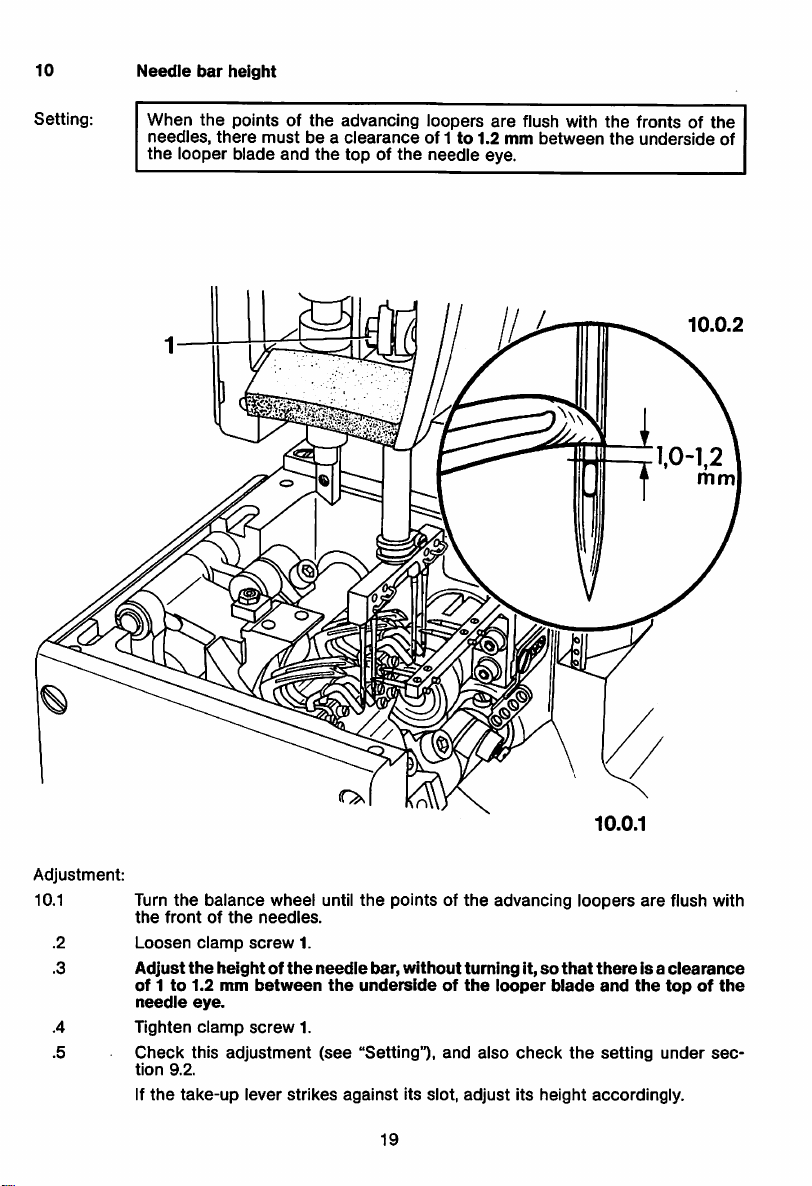
10
Needle
bar
height
Setting:
When
the
needles,
the
looper blade
pointsofthe
there
mustbea
and
advancing
clearance
the
top of
loopers
of 1to1.2mmbetween
the
needle
are
eye.
flush with
the
the
fronts of
underside
the
of
Adjustment:
10.1
.2
.3
.4
.5
Turn
the
frontofthe
Loosen
Adjust
of1to
needle
Tighten
Check
tion
9.2.
if
the
the
balance
clamp
the
wheel
needles.
screw
heightofthe
1.2mmbetween
eye.
clamp
screw
this
adjustment
take-up
lever
until
1.
needle
1.
(see
strikes
the
pointsofthe
bar,
the
without
undersideofthe
"Setting"),
against
its slot,
19
and
m
advancing
tuming
it,sothat
looper
blade
also
check
adjust
its height accordingly.
10.0.1
loopers
thereisa
the
and
setting
are
the
under
flush with
clearance
topofthe
sec
Page 20

11
11.1
Spreader
in
sewing
position
direction
Setting:
Note:
11.0.3
The
spreader
be
13.5
Also, with
distance
The
looper
flush
with
However,
have
dropped
1
points must have a 45®-incllnatlonto
mm
away
from
the
the
from
threads
the
undersideofthe
before
off
11.0.2
maximum
the
spreader
mustberetainedbythe
the
needle
the
stitch
thread
spreader.
spreader
length
pointstothe
ioopers.
drops
bracket.
set
needle
spreaders
off
and
the
the
the
needle
centers
looper,
right,
and
baratb.d.c.,
mustbe2to3 mm.
until
the
needle
the
looper
they must
points
thread
must
the
are
Adjustment
11.1.1
Set
the
Position
thereisa
in
this
right.
Tighten
Loosen
Adjust
the
spreader
Tighten
Check
maximum
spreaders2so
distance
position,
screws
screw4and
spreader
screw
this
turn
1.
bracket3so
points
4.
adjustment
stitch
length
that
of
13.5
mm.
spreaders2so
set
needle
and
the
(see
and
loosen
between
baratb.d.c.
that
thereisa
needle
"Setting").
20
their
that
centers.
screws
points
their
distance
1.
points
and
spreader
are
inclined
of2to3mm
brackets
45°tothe
between
3
Page 21

11.2
Crosswisetosewing
direction
and
looper
Setting:
Note;
11.0.6
At t.d.c. of
between
At l.d.c. of
between
the
spreader
spreader
the
spreader
spreader
brackets3there
point
and
brackets3there
point
and
The spreaders must not touch
11.0.5
0,1 -
0,2
mm
\
looper
spreader
the
mustbea
(Fig. 11.0.5).
mustbea
(Fig.11.0.6).
loopers at any position.
clearance
clearance
of 0.1to0.2
of 0.1to0.2
mm
mm
Adjustment:
11.2.1
Loosen
directly
Adjust
0.2 mm
Tighten
Turn
Position
the
spreader
Tighten
Check
screw4and
above
the
height of
above
screw
the
balance
spreader
screws
this
adjustment
the
the
4.
wheel
bracket3so
points
5.
turn
the
backsofthe
spreader
backsofthe
until
spreader
and
the
loopers
(see
"Setting").
balance
loopers.
bracket
loopers
that
there
21
wheel until
2 so
(Fig. 11.0.5).
bracket
is a
(Fig. 11.0.6).
the
spreaders2are
that
the
spreader
3 is in l.d.c.
clearanceof0.1to0.2mmbetween
and
points
loosen
11.0.4
positioned
are
0.1
screw
to
5.
Page 22
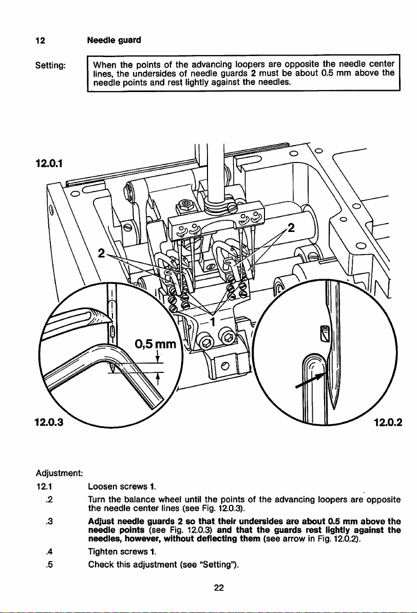
12
Needle
guard
Setting: When the points of the advancing loopers are opposite the needle center
lines,
the
needle
undersidesofneedle
points
and
rest
lightly against
guards 2
the
mustbeabout
needies.
0.5 mm
above
the
o
Adjustment:
12.1
.2 Turn
.3
.4
.5
Loosen
the
the
needle
Adjust
needle
needles,
Tighten
Check
screws
balance
needle
points
however,
screws
this
1.
wheel
center
lines
guards2so
(see
without
1.
adjustment
until
(see
Fig. 12.0.3).
that
Fig. 12.0.3)
deflecting
(see
"Setting").
the
pointsofthe
their
and
22
undersides
that
the
them
(see
advancing
are
about
guards
arrow
loopers
0.5
rest
mm
lightly
in Fig. 12.0.2).
are
above
against
opposite
the
the
Page 23
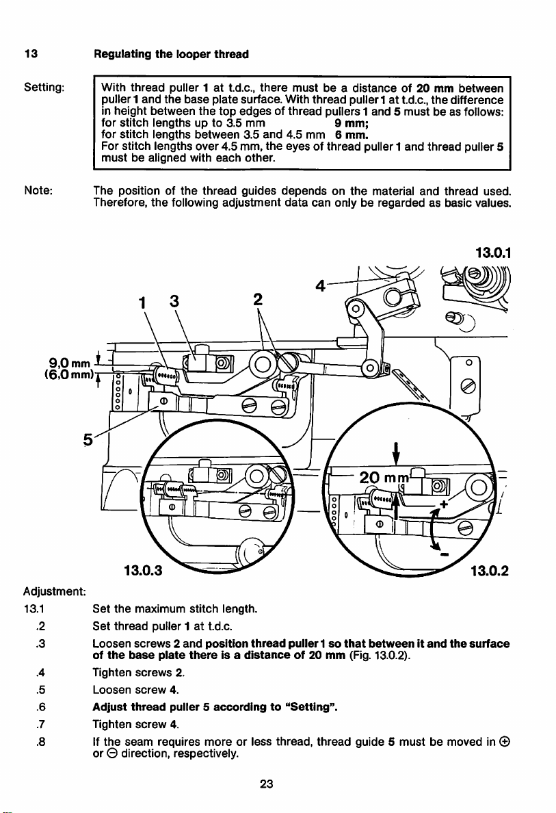
13
Regulating
the
looper
thread
Setting:
Note:
9,0
(6.0
With
puller1
in height
for
for
For
mustbealigned
The
Therefore,
mm
mm)
thread
and
between
stitch
lengths
stitch
lengths
stitch
lengths
position of
the
'•••do
puller 1attd.c.,
the
base
plate
the
top
there
surface.
mustbea
With
edgesofthread
up to 3.5 mm 9 mm;
between
over
with
the
following
4.5 mm,
each
thread
adjustment
3.5
and
other.
guides
the
4.5 mm 6
eyesofthread
dependsonthe
data
thread
puller 1attd.c.,
pullers 1
and5mustbeas follows:
mm.
distanceof20
puller1
and
material
can
onlyberegardedasbasic
mm
the
thread
and
between
difference
puller 5
thread
values.
13.0.1
used.
Adjustment:
13.1
.2
.3
.4
.5
.6
.7
.8
13.0.3
Set
the
Set
thread
Loosen
of
the
Tighten
Loosen
Adjust
Tighten
If
the
maximum
screws2and
base
screws
screw
thread
screw
seam
stitch
length.
puller 1att.d.c.
plate
position
thereisa
2.
4.
puller5accordingto"Setting".
4.
requires more or less thread, thread guide 5 must be moved in ©
or © direction, respectively.
thread
distanceof20
puller1so
23
that
mm
(Fig. 13.0.2).
betweenitand
the
13.0.2
surface
Page 24
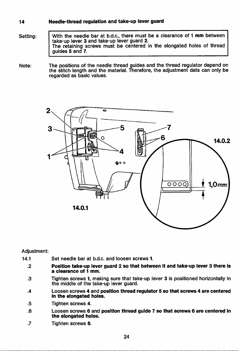
14
Setting:
Needle-thread
With
the
take-up
needle
lever 3
regulation
baratb.d.c.,
and
take-up
and
take-up
there
lever guard 2.
lever
mustbea
The retaining screws must be centered In
guides5and
7.
guard
clearance
the
elongated holes of thread
of 1
mm
between
Note:
The positions of
the
stitch
regardedasbasic
length
14.0.1
the
needle thread guides and
and
the
material.
Therefore,
values.
the
thread regulator
the
adjustment
data
depend
can
only
on
be
14.0.2
Adjustment:
14.1
Set
needle
Position
a
clearance
Tighten
the
middleofthe
Loosen
in
the
Tighten
Loosen
the
elongated
Tighten
baratb.d.c.
take-up
lever
of1mm.
screws1,making
take-up
screws4and
elongated
screws
screws6and
screws
holes.
4.
holes.
6.
and
guard2so
sure
lever
position
position
loosen
that
thread
thread
screws
that
take-up
guard.
24
1.
betweenItand
lever
regulator5so
guide7so
3 is
positioned
that
that
screws6are
take-up
lever3there
screws4are
horizontally In
centered
centered
is
in
Page 25
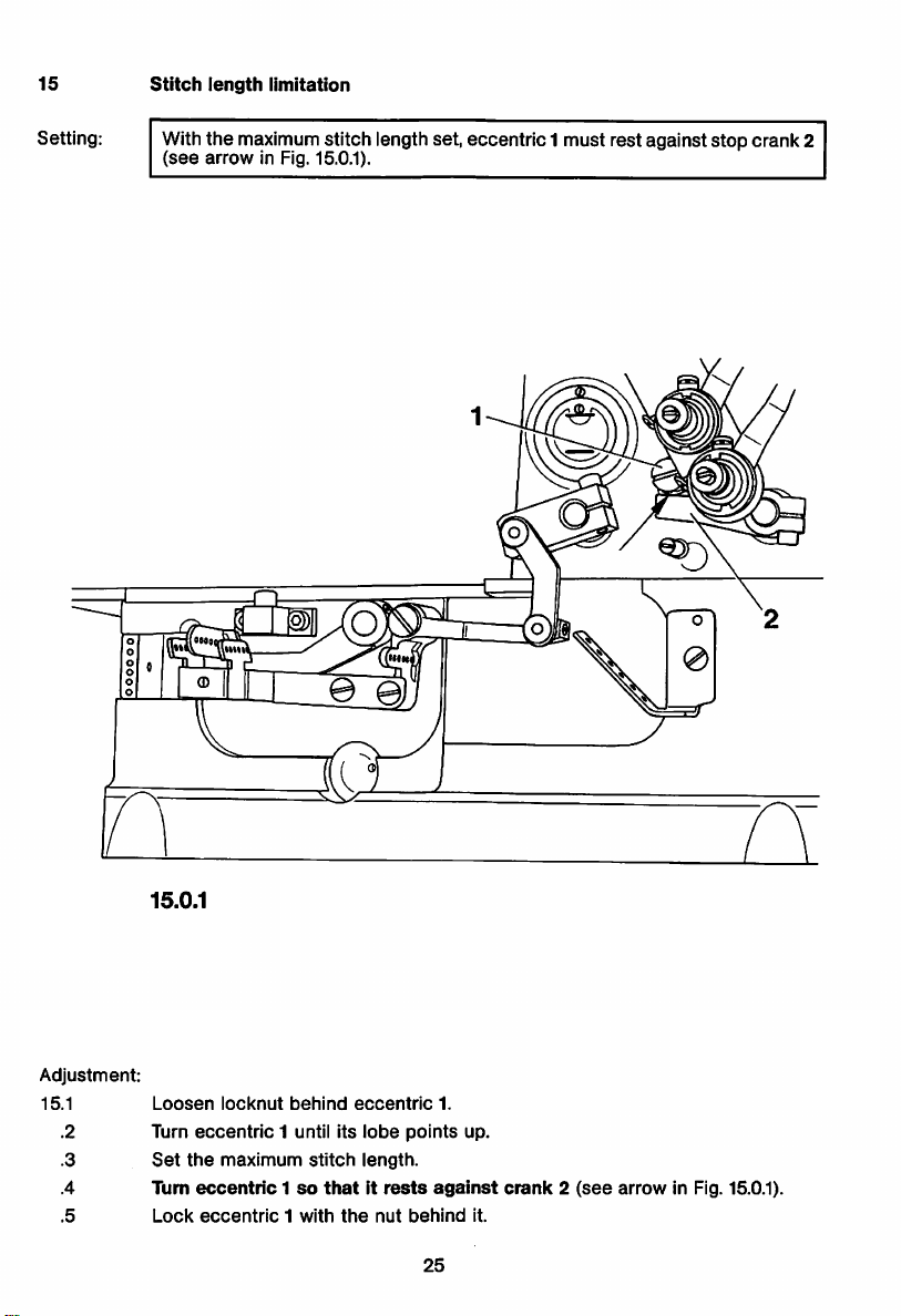
15
Stitch
length
limitation
Setting:
With
(see
the
maximum stitch length set, eccentric1 must rest againststop crank2
arrow
in Fig. 15.0.1).
Adjustment:
15.1
.2
.3
.4
.5
15.0.1
Loosen
Turn
eccentric
Set
the
Turn
eccentric1so
Lock
eccentric1with
iocknut
1 until its
maximum
behind
stitch
thatitrests
the
eccentric
lobe
length.
nut
points
against
behind
25
1.
up.
crank2(see
it.
arrow
in Fig. 15.0.1).
Page 26

Fabric
16
clearance
Setting:
0,3
min
With presser bar lifter 3 raised, there must be a clearance of 7 mm between
presserfoot and needle plate. On machines withfloatingfoot, raisingpresser
bar
lifter 3
must
begins
to lift
clearofthe
On machines with plain hinged
0.3
mm
first raise
iowered
between
and
the
collar 6
presser
16.0.3
the
presser
needle
bar
plate.
presser
and
presser
bar
foot is resting on
by 0.3 mm
foot,
there
bushing 7
the
needie
before
must
when
plate.
the
be a
presser
clearance
the
feed
foot
dog
of
is
16.0.1
16.0.2
26
Page 27

Adjustment;
16.1
Set
needle
baratt.d.c.
.2 Reduce the pressure on presser bar 1 by turning out the regulating screw (see
arrow
in Fig. 16.0.3).
.3 Refit feed dog, cover plate with needle plate, and
.4*
Turn
knurled
nut2until
its
face
sideisflush
with
presser
the
screw.
foot.
.5 Raise the presser bar lifter,loosen screws 4, and place the 7-mm adjustment
gauge
under
the
presser
.6 Push presser bar 1 down until the presser foot rests
gauge
(without pressure),
sewing
presser
direction.
foot.)
(The
foot
and
needles
hinge.
is parallel with
mustbecentered
the
needle
in
lightly
on the adjustment
plate
cutoutasseen
the
needle
holesofthe
.7 Tightenscrews 4 and take the adjustment gauge out from under the presserfoot.
.8* Lower
presser
bar lifter 3 just sufficiently to allow
the
presser
foot to
contact
needle plate with its entire straight sole without exerting any pressure.
.9* Inthis position, loosen screw 5, push collar 6 down until it contacts presser bar
bushing7,then
.10 On
machines
clearanceof0.3 mm
Is
lowered
.11 Turn in
the
pressureonthe
.12* Turn knurled nut 2 to adjust
at varying
.13
Screwonthe
tighten
with plain hinged
betweenItand
and
the
presser
pressure
regulating
presser
speeds
face
(and
plate.
screw5again.
presser
presser
footIsrestingonthe
screw
barsothat
the
proper
the
pressuresothat
material
does
foot
adjust
collar6so
bar
bushing7when
needle
(see
arrow in Fig. 16.0.3) to
feeding is
ensured
proper
not flag).
plate.
even at
feeding Is
that
the
increase
top
ensured
there
feed
speed.
in
the
Is a
dog
the
even
* =
Does
not
applytopresser
feet
without
knurled
nut
2.
27
Page 28

Knee
lever
rest
17
position
and
stroke
limitation
Setting;
When
the
own weight,
more
than7mm.
Also,
the
foot.
17.0.1
knee
knee
lever Is fully
and
the
lever
presser
must
actuated,
foot
must
haveaslight
the
presser
lift
clearofthe
amountofplay
bar
before
lifter
needle
must
plate
lifting
drop
by a little
the
presser
by its
Adjustment:
17.1
.2
.3
.4
.5
.6
.8
.9
.10
Make
sure
that
foot
onto
Loosen
TurnInscrew
Turn
screw1backbyabout
the
knee
Loosen
Raise
the
ment
gauge
Push
the
adjustment
Hold
the
Release
the
nut.
Check
this
the
the
needle
nutofscrew1and
1 until
lever
mustbeat
nutofscrew2and
presser
under
knee
gauge.
knee
leverinthis
the
knee
adjustment
knee
lever is
platebymeansofthe
turn
the
presser
half a
about
turn
foot
with
the
levertothe
the
presser
right
position
lever,
turn
screw2backbyabout
(see
"Setting").
inserted
out
screw
foot
turn
right
the
screw
lifting
foot
from
until
and
28
in its
connection,
lifting lever.
by a
few
beginstolift
and
tighten
anglestothe
out
by a
lever
and
place
the
rear.
the
presser
turn
the
left
then
lower
turns.
from
the
needle
its locknut. (In
base
plate.)
few
turns.
the
10-mm-thick
foot
beginstolift
screwinas
half a
turn
and
the
presser
plate.
this
position,
adjust
off
the
farasit willgo.
lock
it with
Page 29

18
Tension
release
Setting:
When
the
tensions6mustbereleased.
presser
foot Is raised with
•
00
the
knee
lever by
fo 6 6 6 6 6
about
10 mm,
thread
Adjustment:
18.1
.2
.3
18.0.2
Loosen
Raise
the
screw
presser
Turn fixing
pieceofcrank
this
position,
In
by
about1mm.
Tighten
Check
clamp
this
Screwoncover
1.
foot
collar
2 (In
4.
push
screw
adjustment
plateatthe
with
the
knee
leverbyabout
directionofarrow)
tension
release
1.
(see
"Setting").
backofthe
29
plate
until
crank
5 fully
machine.
10 mm
and
3 Is
resting
downwards,
retain this position.
against
then
the
angle
haveItreturn
Page 30

PFAFF
PFAFF
Postfach
KonigstraRe
D-6750
Telefon;
Telefax;
Telex:
Weber
PrintedinWest-Germany
3020/3040
154
Kaiserslautern
(0631)
(0631)17202
45753
200-0
 Loading...