

Pfaff 5483, 5483H Service Manual
k.®
5483
Service
5483
Manual
H
Pfaff,D6750
Kaiserslautem,
Postfach
Telefax
3020/3040,
(0631)
17202
Telefon
(0831)
200-0,
Telex
45753
Service
Notesonsafety:
The
When
Service
Work on live
VDE
Please
The
chainstitch,
Pfaff
Manual
machine
0105.
must
converting
and
repair
partsisnot
note:
illustrationsinthis
high-speed
5483-814/01
Differing or additional
660-91)
are
givenonpage
mechanisminthe
The
machine
for
the
onlybeused
it to
another
work
must
sewing
single-
adjusting
Pfaff
for
version, ali valid
onlybeperformedbyqualified
permitted,
Manual
and
38,
show
machine,
two-needle
instructions
and
5483
the
purposeithas
safety
rules
apart
from
exceptions
the
Pfaff
5483-814/01
whereas
for
machinesinversionHand
machines.
for
machines
the
Appendicesonpages40and44respectively.
versionisindicatedonthe
model
plateonthe
been
designed
mustbefollowed.
personnel.
according
single-needle,
adjusting
instructions
with floating
with -911/..
arm
for.
to DIN
foot
standard.
57105
two-thread
applytothe
(No. 91-055
backtacking
and
Tools,
gauges
Setofscrewdrivers
Setofalien
Setofopen-ended
Spanner/wrench,
Metal
rule
C-clamp
Adjustment
Gauge
Gauge
Packetofneedles
Needle
Spacers;
Shims:
Thread
and
keysofsizes
No.
08-880137-00
pin(5mm
No.
61-111642-19or08-880179-00
No.
61-111643-06
system:
0.3, 0.5,
0.3or0.6
and
material
other
equipment
with
blades
1.5to6.0
spanners/wrenches
22
mm
wide
dia.) No.
4463-35
in
version
in
versionHwithout
in
version
in
version
0.8
mm
or 1.2
thick
for
-911/..,
-814/01
-814/02
mm
(for
testing
needed
from2to10mm
mm
13-030341-05
5463-35
HO,
HO,
thick
subcl.
for
from7to14mm
-911/..,UY128
4463
4463-8FLand
-911/..)
purposes
KK
adjusting
wide
GAS
the
wide
4463-8
Pfaff
FR
5483:
1
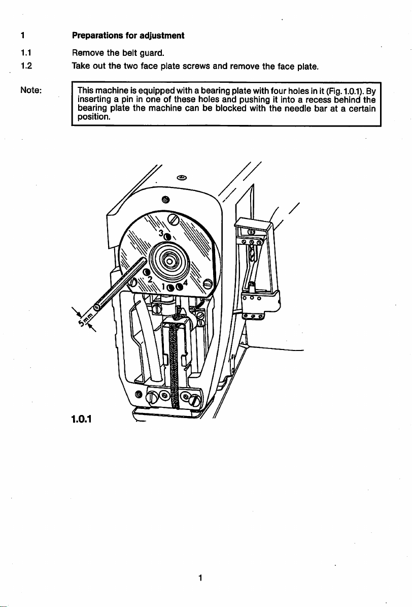
Preparations
for
adjustment
1.1
Remove
1.2 Take
Note:
This machineIs
Inserting a pin In
bearing
position.
out
the
the
plate
belt
two
equipped
the
guard.
face
plate
oneofthese
machine
screws
and
remove
the
face
plate.
with a bearingplatewithfour holes InIt (Fig.
holes
and
canbeblocked
pushing It Into a
with
the
needle
recess
barata
behind
1.0.1).
certain
By
the
1.0.1
P
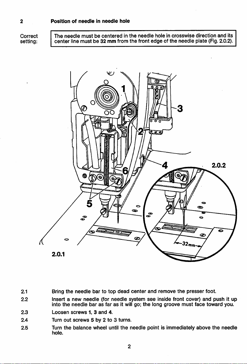
Position
of
needieinneedie
hoie
Correct
setting:
The
center
needle
mustbecenteredInthe
line
mustbe32mmfrom
the
needle
front
edgeofthe
holeIncrosswise
needle
direction
plate
(Fig. 2.0.2).
and
Its
2.1 Bring
2.2
insertanew
Into
2.3
2.4
2.5
Loosen
Turn
Turn
hole.
the
out
the
the
needle
needle
screws
screws
balance
bartotop
needle
(for
dead
needle
barasfarasIt will go;
1, 3
and
4.
5 by 2to3
wheel
until
turns.
the
center
system
needle
and
the
see
remove
Inside
long
the
front
groove
pointIsImmediately
presser
cover)
must
face
above
foot.
and
toward
push
the
It up
you.
needle
2.6
Adjust
the
the
positionofthe
needle
holeIncrosswise
distanceof32
lineofthe
needle.
mm
between
2.7 In this position, tighten
screw
1,pull
2.8 Using
Then
2.9
Loosen
has
occurredinthe
2.10 Tighten
bar.
tighten
screw3again,
both
screw
screws
the
1.
needle
needle
screw
guide
stud
turn
the
bar
5, making
bar
direction
the
front
3 Just lightly
behind it
balance
frame,
sure
that
framesothat
and
thatInsewing
edgeofthe
and
screw
against
the
wheel
a few
then
tighten
slotted
guide
the
needleIscentered
direction
needle
plate
4 securely.
eyeofneedle
turnstomake
screw
3 again.
6 is parallel to
there
and
the
center
bar
frame
surenotwist
the
needle
In
Is a
2.
2.11
Check
this
adjustment
(see
"Correct
setting").
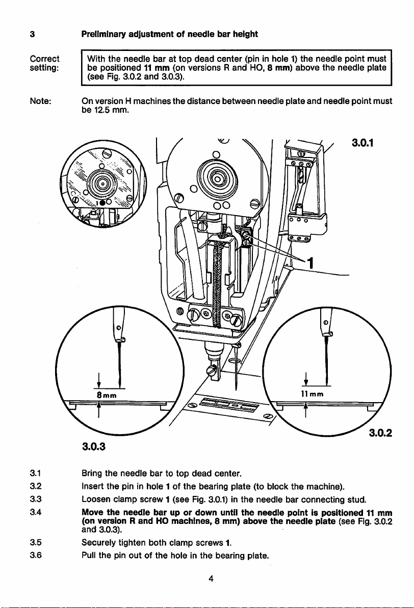
Preliminary
adjustmentofneedle
bar
height
Correct
setting;
Note:
With
the
be
(see
On
be
needle
positioned11mm
Fig.
3.0.2
versionHmachines
12.5
mm.
barattop
and
3.0.3).
dead
(on
versionsRand
the
distance
center
between
(pin In
HO, 8
needle
hole1)the
mm)
above
plate
and
needle
the
needle
point
needle
point
must
plate
must
3.0.3
3.1 Bring
3.2 Insert
the
the
needle
pin In
3.3 Loosen clamp
3.4
Move
the
needle
(on version R
and
3.0.3).
3.5
3.6
Securely
Pull
the
tighten
pin
bartotop
hole
1 of
the
screw1(see
barupor
andHOmachines,
both
clamp
outofthe
holeInthe
dead
center.
bearing
Fig. 3.0.1) in
down
until
8 mm)
screws
1.
bearing
plate
the
the
above
(to
needle
needle
plate.
block
the
machine).
bar
connecting
pointispositioned11mm
the
needle
plate
(see
stud.
Fig. 3.0.2
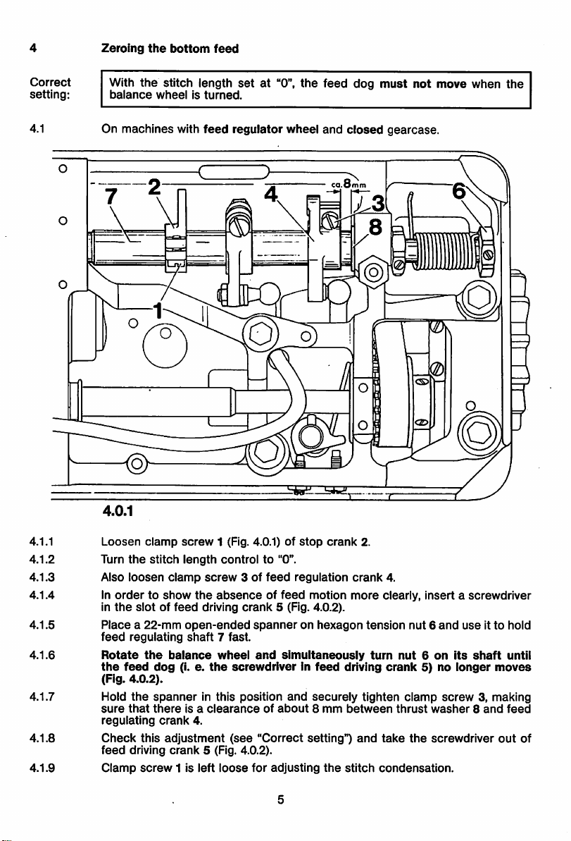
Zeroing
the
bottom
feed
Correct
setting;
4.1
With
the
balance
stitch
wheelIsturned.
On machines with
length
feed
setat"0",
regulator
the
wheel
feed
and
dog
closed
©
must
gearcase.
not
move
0
when
the
4.0.1
4.1.1
4.1.2
Loosen
Turn
4.1.3 Also
4.1.4 In
In
4.1.5
4.1.6
Placea22-mm
feed
Rotate
the
(Fig.
4.1.7 Hold
sure
regulating
4.1.8
4.1.9
Check
feed
Clamp
clamp
the
stitch
loosen
clamp
ordertoshow
the
slotoffeed
regulating
the
4.0.2).
the
that
this
driving
screw
balance
dog
spanner
there
crank
adjustment
crank
11s
feed
screw
1 (Fig. 4.0.1)ofstop
length
controlto"0".
screw
the
absenceoffeed
driving
open-ended
shaft
7 fast.
wheel
(1.e.the
screwdriverinfeed
In this
Is a
clearance
4.
(see
5 (Fig. 4.0.2).
left
loose
3 of
feed
regulation
crank
spanneronhexagon
and
position
of
"Correct
for
motion
5 (Fig. 4.0.2).
simultaneously
and
securely
about8mm
setting")
adjusting
crank
the
2.
crank
more
tension
driving
tighten
between
and
stitch
4.
clearly,
nut6and
turn
nut6on
crank
5) no
clamp
thrust
take
the
condensation.
Insertascrewdriver
useItto
its
ionger
shaft
hold
untii
moves
screw3,making
washer8and
screwdriver
feed
out
of
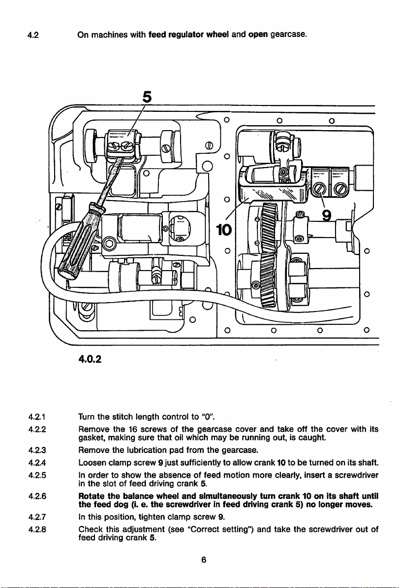
4.2
On
machines
with
feed
regulator
wheel
and
open
gearcase.
4.0.2
4.2.1 Turn
4.2.2
Remove
gasket,
4.2.3
4.2.4
4.2.5
4.2.6
Remove
Loosen
In
in
the
Rotate
the
4.2.7 In
4.2.8
Check
feed
the
stitch
the16screwsofthe
making
the
lubrication
clamp
screw9just
ordertoshow
slotoffeed
the
balance
feed
dog
(i.e.the
this
position,
this
adjustment
driving
crank
length
controlto"0".
sure
that
pad
the
absenceoffeed
driving
wheel
screwdriverinfeed
tighten
clamp
(see
5.
gearcase
oil
which
mayberunning
from
the
gearcase.
sufficientlytoallow
motion
crank
5.
and
simultaneously
screw
9.
"Correct
setting")
cover
and
take
off
out,iscaught.
crank10tobeturnedonits
more
clearly,
insertascrewdriver
tum
crank5)no
and
take
crank10on
the
screwdriver
driving
the
cover
Its
longer
shaft
moves.
with
out
its
shaft.
until
of
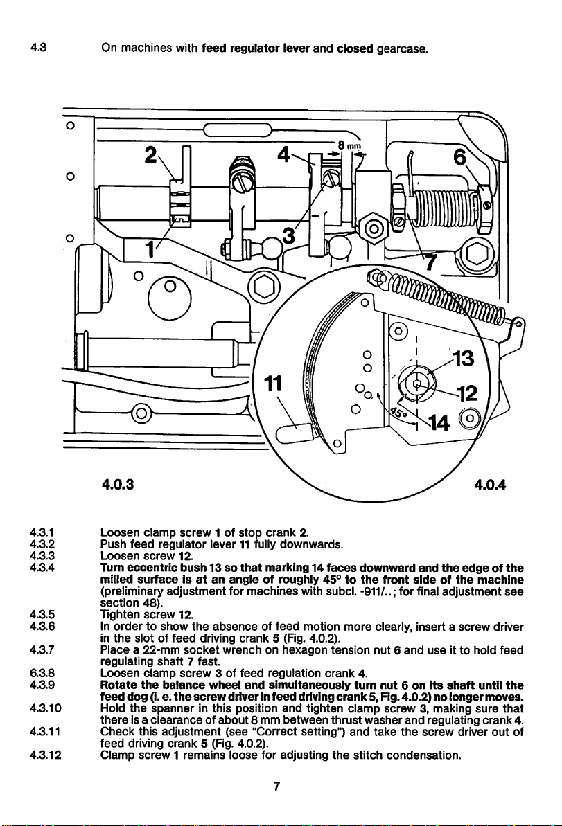
4.3
On
machines
with
feed
regulator
lever
and
closed
gearcase.
©
4.3.1
4.3.2
4.3.3
4.3.4
4.3.5
4.3.6
4.3.7
6.3.8
4.3.9
4.3.10
4.3.11
4.3.12
Loosen
Push
Loosen
Turn
milled
(preliminary
section
Tighten
In
In
Placea22-mm
regulating
Loosen
Rotate
feed
Hold
there
Check
feed
Clamp
clamp
screw
feed
regulator
screw
eccentric
surfaceisatanangleofroughly
adjustment
48).
screw
ordertoshow
the
slotoffeed
shaft7fast.
clamp
the
balance
dog
(i.e.
the
spannerInthis
Isa
clearanceofabout
this
adjustment
driving
crank
screw1remains
12.
bush13so
12.
the
driving
socket
screw
the
screw
5 (Fig. 4.0.2).
1 of
lever
for
absenceoffeed
wrenchonhexagon
3 of
wheel
driver in
(see
loose
stop
crank
11 fully
downwards.
that
marking14faces
machines
crank
5 (Fig. 4.0.2).
feed
regulation
and
simultaneously
feed
position
8 mm
"Correct
for
adjusting
2.
with
motion
driving
and
tighten
between
setting")
downward
45°tothe
subcl.
-911/..; for final
more
tension
crank
4.
turn
crank
clamp
thrust
washer
and
the
stitch
and
front
sideofthe
clearly,
Insertascrew
nut6and
nut6on
use
its
5, Fig.4.0.2)no
screw3,making
and
take
regulating
the
screw
condensation.
the
edgeofthe
machine
adjustment
It to
hold
shaft
until
longer
moves.
sure
crank
driver
see
driver
feed
the
that
out
4.
of
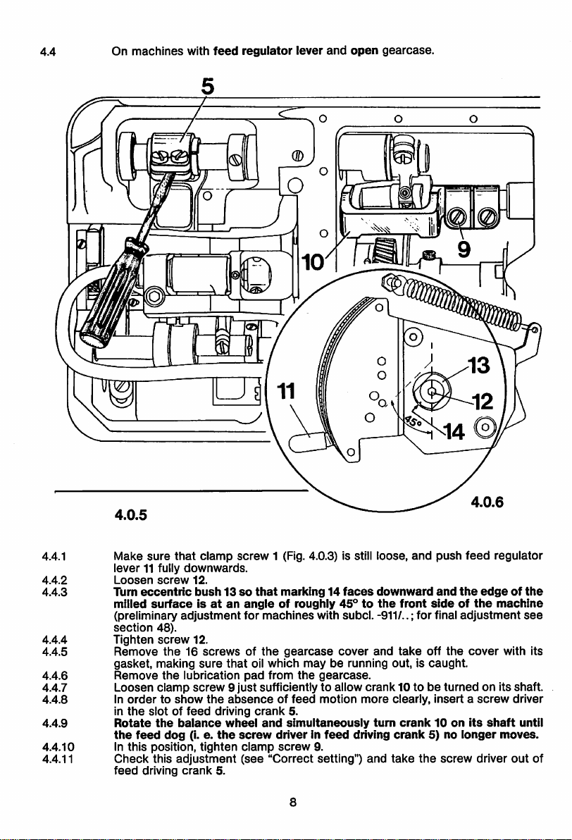
4.4
On
machines
with
feed
regulator
lever
and
open
gearcase.
4.4.1
4.4.2
4.4.3
4.4.4
4.4.5
4.4.6
4.4.7
4.4.8
4.4.9
4.4.10
4.4.11
4.0.5
Make
sure
that
clamp
lever
11 fully
Loosen
Turn
eccentric
milled
(preliminary
section
Tighten
Remove
gasket,
Remove
Loosen
In
ordertoshow
in
the
Rotate
the
feed
In
this
Check
feed
downwards.
screw
12.
surfaceisatanangleofroughly
adjustment
48).
screw
12.
the16screwsofthe
making
the
lubrication
clamp
screw9just
slotoffeed
the
balance
dog
(i. e.
position,
this
adjustment
driving
crank
screw
bush13so
sure
that
the
absenceoffeed
driving
wheel
the
screw
tighten
5.
for
pad
clamp
(see
1 (Fig. 4.0.3) is still loose,
that
marking14faces
machines
gearcase
oil
which
from
45°tothe
with
subcl.
cover
mayberunning out, is
the
gearcase.
sufficiently to allow
motion
crank
5.
and
simultaneously
driverinfeed
screw
"Correct
8
driving
9.
setting")
and
downward
front
-911/..; for final
and
take
off
crank
10 tobeturnedonits
more
clearly,
turn
crank10on
crank
and
take
the
push
feed
and
the
adjustment
the
cover
edgeofthe
sideofthe
caught.
insertascrew
its
5) no
longer
screw
driver
regulator
machine
with its
shaft.
driver
shaft
moves.
out
see
until
of
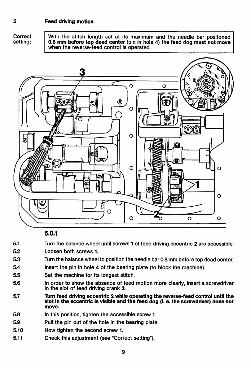
Feed
driving
motion
Correct
setting:
With
0.8
when
the
mm
the
stitch length
before
top
reverse-feed
setatits maximum
dead
center
(pin in
controlisoperated.
and
hole4)the
the
feed
needle
dog
bar positoned
must
not
move
5.0.1
5.1 Turn
5.2
Loosen
5.3 Turn
5.4
5.5
5.6
Insert
Set
In
in
5.7
Turn
slotInthe
move.
5.8
5.9
5.10
5.11
In
Pull
Now
Check
the
balance
both
screws
the
balance
the
pin in
the
machine
ordertoshow
the
slotoffeed
feed
driving
eccentricIsvisible
this
position,
the
pin
outofthe
tighten
the
this
adjustment
wheel
until
screws1of
1.
wheel
to position
hole
4 of
the
for
its
longest
the
absenceoffeed
driving
crank
eccentric2while
tighten
the
accessible
holeinthe
second
screw
(see
"Correct
the
bearing
stitch.
3.
and
the
bearing
1.
9
feed
needle
plate
motion
operating
feed
screw
setting").
bar
(to
dog
1.
plate.
driving
0.8 mm
block
more
the
reverse-feed
(I. e.
eccentric2are
before
top
the
machine).
clearly,
insertascrewdriver
the
control
screwdriver)
accessible.
dead
center.
until
does
the
not
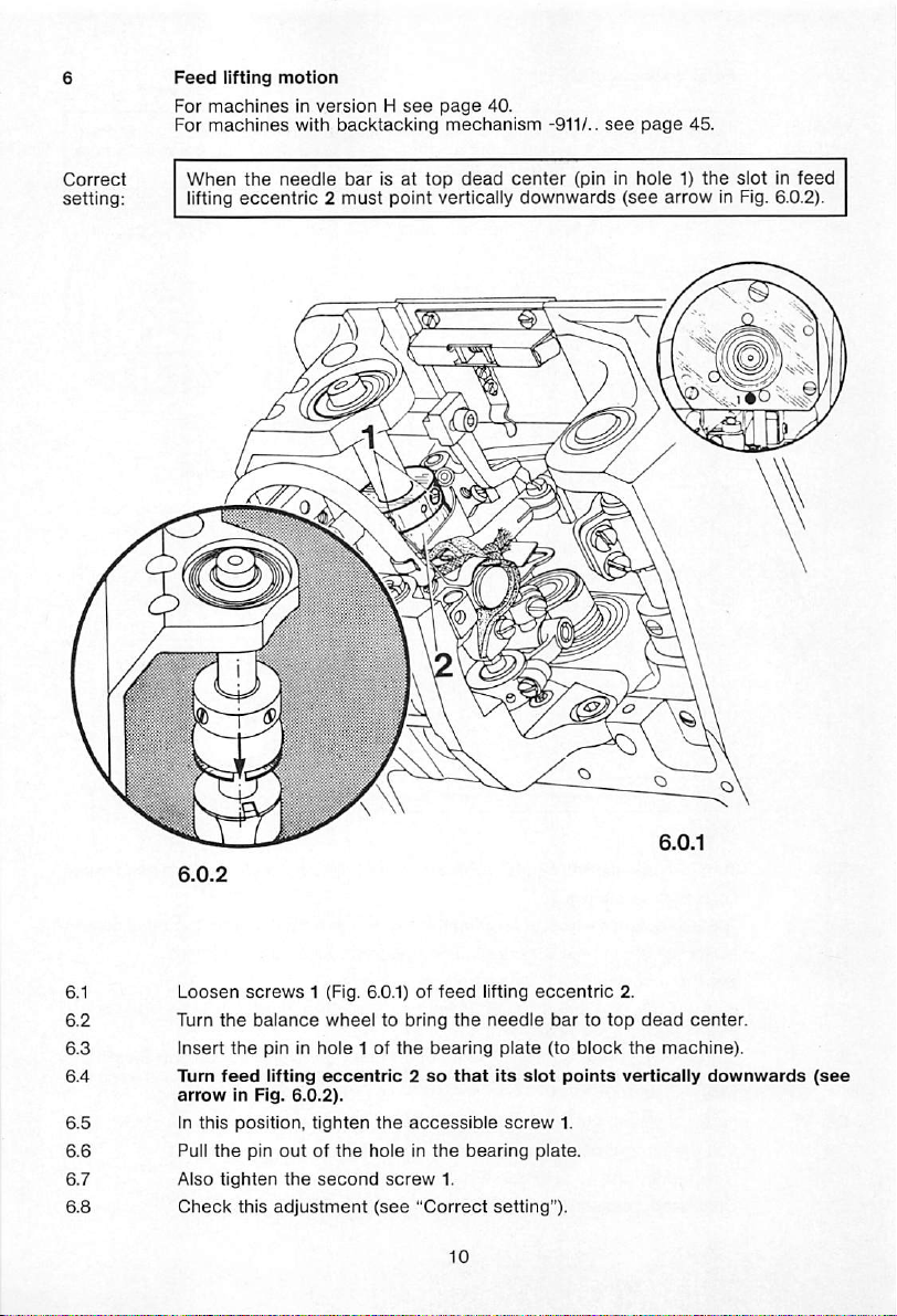
Feed
lifting
motion
For
machinesInversionHsee
For
machines
When
lifting
w/ith
backtacking
the
needle
eccentric2must
bar is at
point
page
mechanism
top
dead
vertically
40.
center
downwards
-911/..
see
(pin in hole 1)
(see
page
45.
arrow
the
slot in
in Fig. 6.0.2).
feed
Loosen
Turn
insert
Turn
arrow
In
this
Pull
Also
Check
screws
the
balance
the
pininhole1of
feed
lifting
in Fig.
position,
the
pin
tighten
this
1 (Fig. 6.0.1) of
wheeltobring
eccentric2so
6.0.2).
tighten
outofthe
the
second
adjustment
the
bearing
the
accessible
holeinthe
screw
(see
"Correct
feed
the
that
1.
lifting
needle
plate
its
bearing
setting").
slot
screw
eccentric
bartotop
(to
block
points
1.
plate.
2.
dead
the
machine).
vertically
center.
downwards
(see
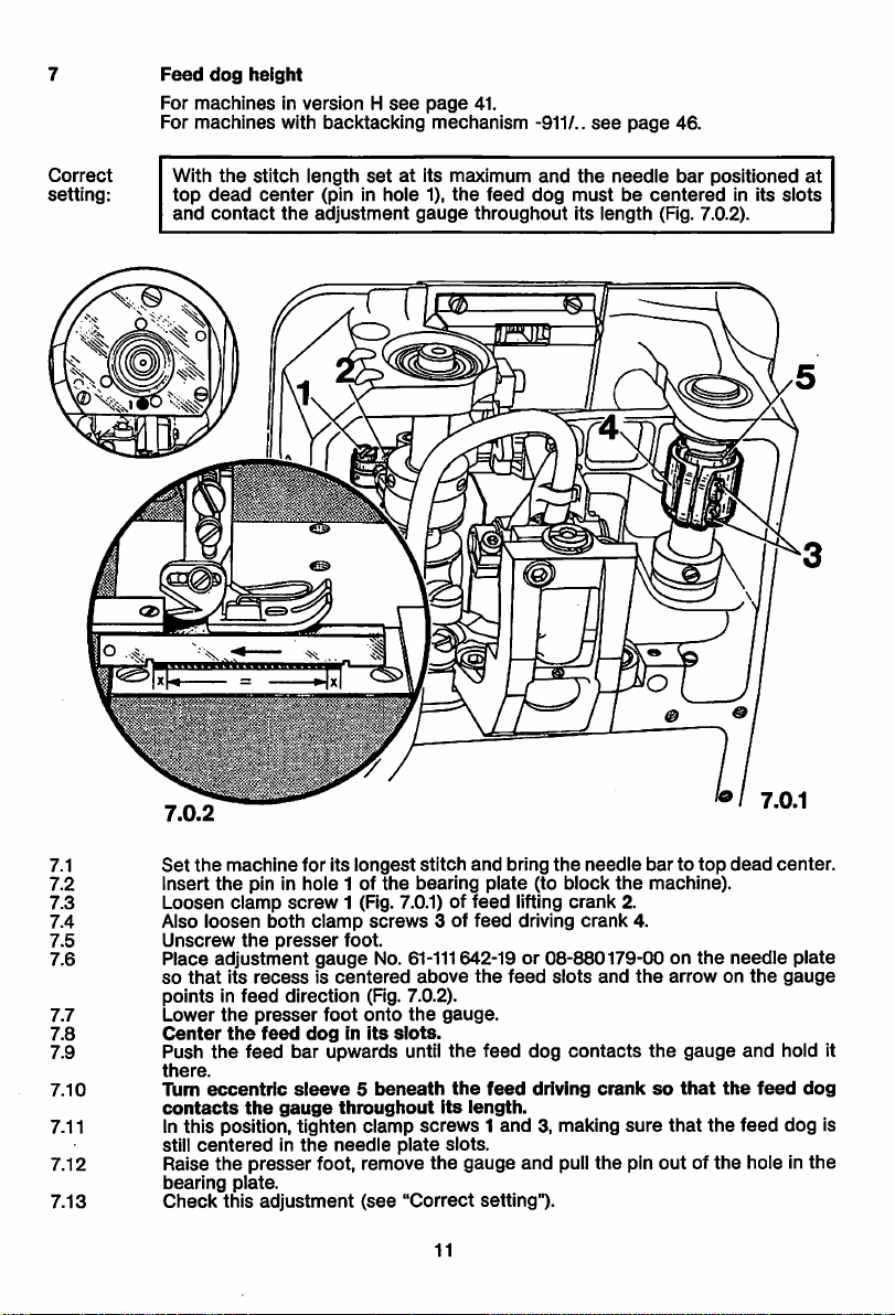
7
Feed
dog
height
For
machinesinversionHsee
For
machines
with
backtacking
page
41.
mechanism
-911/..
see
page
46.
Correct
setting:
With
top
and
7.0.2
the
dead
contact
stitch
center
the
length
setatits maximum
(pin in
adjustment
hole
1),
gauge
the
feed
throughout
and
the
dog
needle
mustbecentered
its
length
bar
positioned
(Fig. 7.0.2).
f
in its
at
slots
7.0.1
7.1
7.2 Insert
7.3
7.4 Also
7.5
7.6
7.7
7.8
7.9 Push
7.10
Set
the
machine
the
Loosen
pin in hole 1 of
clamp
loosen
Unscrew
Place
so
adjustment
that
its
the
recessiscentered
pointsinfeed
Lower
the
Center
there.
Turn
contacts
presser
the
the
feed
eccentric
the
for its
screw
both
clamp
presser
gauge
direction (Fig. 7.0.2).
foot
feed
doginits
bar upwards until
sleeve5beneath
gauge
7.11 In this position, tighten
still
7.12 Raise
7.13
bearing
Check
centeredinthe
the
presser
plate.
this
adjustment
needle
foot, remove
longest
1 (Fig. 7.0.1) of
foot.
the
screws
stitch
bearing
3 of
and
plate
feed
feed
bring
(to block
lifting
driving
the
needle
crank
crank
No. 61-111642-19 or 08-880179-00 on
above
the
feed
slots
and
onto
the
gauge.
siots.
the
feed
dog
contacts
the
feed
driving
throughout
clamp
plate
(see
"Correct
its
length.
screws1and
slots.
the
gauge
setting").
11
and
cranksothat
3, making
pull
the
bartotop
the
2.
4.
the
the
sure
pin
machine).
the
arrowonthe
gauge
that
the
outofthe
dead
needle
and
the
feed
hole in
feed
center.
plate
gauge
hold it
dog
dog
the
is
stitch
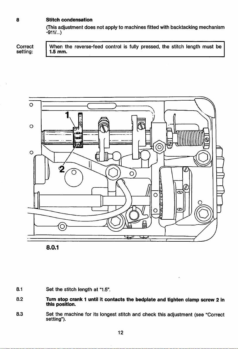
(This
-911/..)
condensation
adjustment
does
not
applytomachines
fitted
with
backtacking
mechanism
Correct
setting:
When
1.5
mm.
the
reverse-feed
control
is fully
pressed,
©
the
stitch
'VW
length
mum
Q)
must
be
8.0.1
8.1
Set
8.2 Turn
this
8.3
Set
setting").
the
stitch
lengthat"1.5".
stop
crank
position.
1 until it
the
machine for Its longest stitch
contacts
the
bedplate
and
12
check
and
tighten
clamp
this adjustment
(see
screw
"Correct
2 in
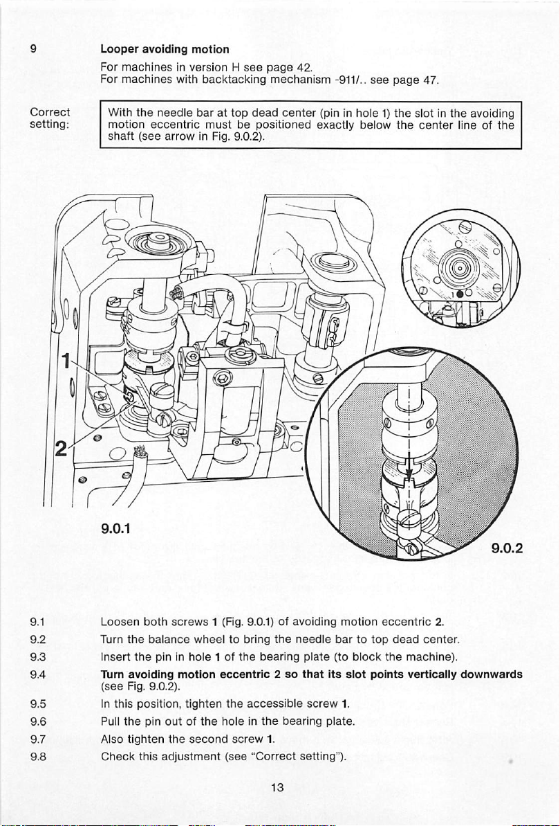
Looper
For
For
I
avoiding
machinesinversionHsee
machines
With
the
motion
shaft
eccentric
(see
motion
with backtacking
needle
barattop
arrow
in Fig. 9.0.2).
page
mechanism
dead
mustbepositioned
center
42.
-911/..
(pininhole1)the
exactly
see
below
page
the
47.
slotinthe
center
avoiding
line of
the
Loosen
Turn
Insert
Turn
(see
In
this
Pull
Also
Check
both
the
balance
the
avoiding
Fig.
9.0.2).
position,
the
pin
tighten
this
screws
wheeltobring
pin in
hole
motion
tighten
outofthe
the
second
adjustment
1 (Fig. 9.0.1)ofavoiding
the
needle
1 of
the
bearing
eccentric2so
the
accessible
holeinthe
screw
(see
bearing
1.
"Correct setting"). ,
plate
that
screw
motion
bartotop
(to
block
Its
slot
1.
plate.
eccentric
the
points
dead
machine).
vertically
2.
center.
downwards
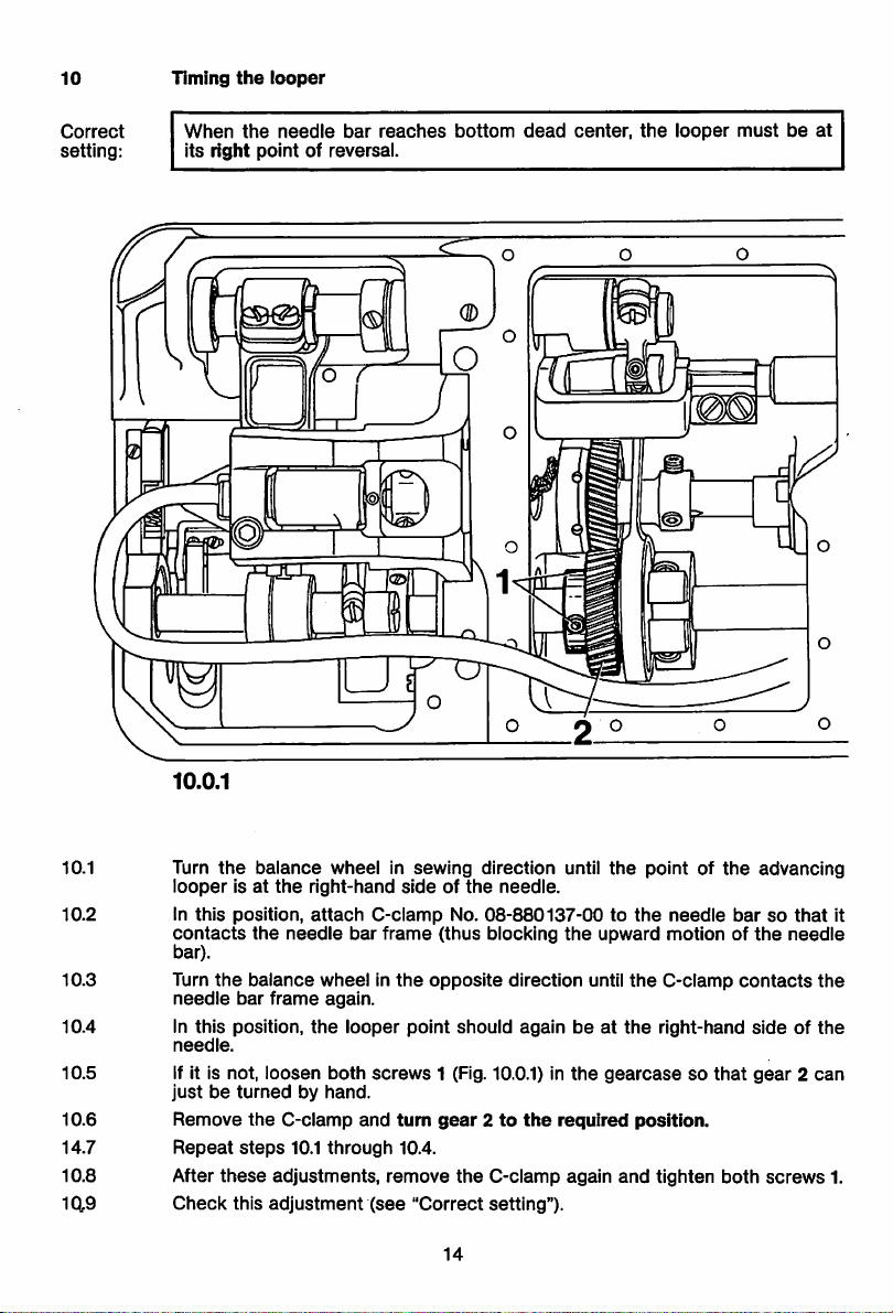
Timing
the
10
looper
Correct
setting:
When
its
right
the
needle
point
bar
reaches
of reversal.
J
bottom
dead
center,
the
looper
mustbeat
10.0.1
10.1 Turn
10.2 In
10.3
10.4 in
the
looperisat
this
position,
contacts
bar).
Turn
the
needle
this
position,
needle.
10.5 if it is not,
justbeturnedbyhand.
10.6
14.7
10.8 After
1(19
Remove
Repeat
Check
these
this
balance
the
the
needle
balance
bar
frame
loosen
the
C-clamp
steps
adjustments,
adjustment
wheel in
right-hand
attach
wheelinthe
again.
the
both
10.1
through
C-clamp
bar
frame
looper
screws
and
(see
sewing
sideofthe
(thus
opposite
point
1 (Fig. 10.0.1) in
tum
gear2to
10.4.
remove
"Correct
14
direction until
needle.
No.
08-880137-00tothe
blocking
the
direction
should
againbeat
the
the
required
the
C-clamp
setting").
again
the
pointofthe
needle
upward
until
motionofthe
the
C-clamp
the
right-hand
gearcasesothat
position.
and
tighten
advancing
barsothat
contacts
sideofthe
gear2can
both
screws
it
needle
the
1.

11
Looper
For
heightonmachines
machines
in version H
without
see
page
subcl.
43.
-900/..
For machines with backtacking mechanism -911/..
see
page
48.
Correct
setting:
When
the
looper
holder
of 0.7 mm
needle
On
front
between
plate on single-needle machines (Fig.
two-needle
looper
machines,
and
is in its vertical position,
the
highest
the
there
needle
pointofthe
mustbea
plate.
there
and
mustbea
the
looper
11.0.2).
clearanceof1.0
clearance
undersideofthe
mm
between
the
11.1
11.2
11.3
11.4
11.5
11.6
Remove
Place
the
Turn
Loosen
Turn
highest
of
In
Continuedonnext
the
presser
balance
eccentric
1.0
this
bed
slide,
needle
foot
wheel
clamp
pointofthe
mm
between
position,
screw1and
bearing
tighten
cover
plate
onto
Inposition
the
until
stud3until
looper
front
clamp
page.
plate,
needle
the
screw
and
looper
looper
needle
plate
again
and
plate.
holderisvertical.
2 of
eccentric
there
the
undersideofthe
and
needle
screw1and
15
and
feed
dog.
operate
is a
the
bearing
clearanceof0.7
needle
plateontwo-needle
screw
2.
presser
stud
plate
bar
lifter to lower
3.
mm
between
(or a
clearance
machines).
the

11.7 Ifa
proceedasfollows;
clearance
of 0.7 mm (or 1.0mm on
two-needle
machines)
cannotbeobtained,
10.7.1 Raise
11.7.2
11.7.3 Fitanappropriate
11.7.4
11.7.5
11.7.6
11.8
11.9
Loosen
spacer).
the
looper
Set
the
liminary
Replace
foot
onto
Check
between
when
If
necessary,
Check
the
presser
clamp
into
looper
adjustment)
the
needle
the
that
there
the
the
looper
this
adjustment
screw
needle
highest
repeat
foot
and
remove
4 in
looper
spacer
looper
blade
(see
holder5againasfarasit will go.
roughly parallel to
and
tighten
plate
and
the
holder5and
inside
clamp
operate
needle
front
the
plate.
is a
clearance
pointofthe
holder
is in its vertical position.
steps
(see
11.3
"Correct
of 0.7
looper
through
mm
11.6.
setting").
plate.
take
off
the
cover)onthe
the
front
screw
4.
presser
(or 1.0 mmontwo-needle
and
the
looper
edgeofthe
bar
liftertolower
undersideofthe
looper
(do
neck
and
bedplate
the
machines)
needie
not
push
(pre
presser
plate
lose
16
 Loading...