

Page 1
481
Service
PFAFF
INDUSTRIEMASCHINEN
Manual
GMBH
KAiSERSLAUTERN
Page 2
Instructions
and
Illustrated Guide for
for Adjusting
Tape-Recorded
the
Instructions
Pfaff 481
Important
Never
damage
length
with the reverse-feed control depressed, that means with the machine
wardsata
note
use a
C-clamp
Its
special
of "0"on
stitch
on the needle bar of
coating.
Model
lengthof1.5
Furthermore,
N machines have to be carried out at a stitch length of 1.5mmand
mm.
Pfaff
480 series
all adjustments
machines
which
are to be made at a
because this
set
for sewing back
would
stitch
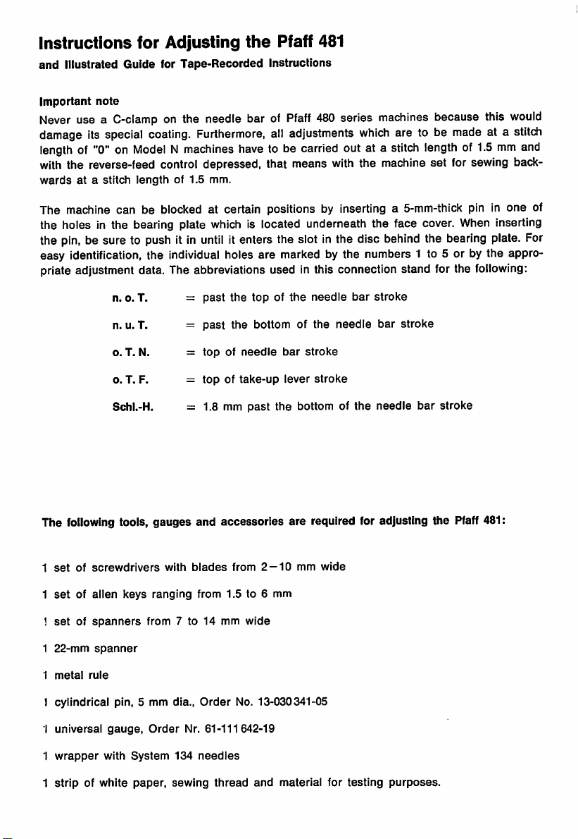
The machine can be blocked at certain positions by Inserting a 5-mm-thlck pin In one of
the holes In the bearing plate
the
pin,
be sure to push ItInuntil
which
Is located underneath the face cover.
Itenters the slotInthe disc
behind
the bearing plate. For
When
Inserting
easy Identification, the Individual holes are marked by the numbers 1 to 5 or by the appro
priate adjustment data. The abbreviations used In this connection stand for the
n. o. T. =
n. u. T. =
o. T. N. =
o. T. F. =
Schl.-H. = 1.8 mm
past
the
topofthe
past
the
bottom of
topofneedle
topoftake-up
past the
bar
stroke
lever
bottom of
needle
the
stroke
bar
needle
the
stroke
bar
needle
stroke
bar
following:
stroke
The following tools, gauges and accessories are required for adjusting the Pfaff481;
1
setofscrewdrivers
1
setofalien
1
setofspanners
1
22-mm
spanner
1
metal
rule
1 cylindrical pin, 5 mm dia..
1
universal
1
wrapper
1
stripofwhite
gauge.
with
keys
System
paper,
with
ranging
from
Order
blades
from
7 to 14 mm
Order
Nr.
61-111642-19
134
needles
sewing
thread
from
2 —10mm
1.5
to 6 mm
wide
No. 13-030341-05
and
material
wide
for
testing
purposes.
Page 3
1.
Preparations
for
adjusting
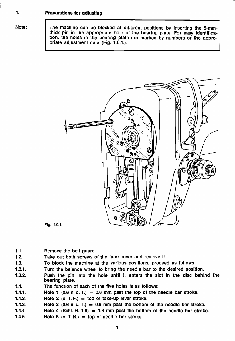
Note:
The machine can be blocked at different positions by inserting the 5-mm-
thick pin in the appropriate hoie of the bearing plate. For easy identifica
tion,
the
priate
holes in
adjustment
the
bearing plate
data
(Fig. 1.0.1.).
are
marked by numbers or
the
appro
Fig.
1.0.1.
1.1.
1.2.
1.3.
1.3.1.
1.3.2.
1.4.
Remove
Take
To
Turn
Push
bearing
The
the
belt
out
both
screws
block
the
machineatthe
the
balance
the
pin into
plate.
functionofeachofthe
guard.
of
the
wheeltobring
the
hole
five
1.4.1. Hole 1 (0.6 n. o. T.) = 0.6 mm
1.4.2.
1.4.3.
1.4.4.
1.4.5.
Hole
2 (o. T. F.) =
Hole
3 (0.6 n. u. T.) = 0.6 mm
Hole
4 (Schl.-H. 1.8) = 1.8 mm
Hole
5 (o. T. N.) =
topoftake-up
topofneedle
face
cover
various
the
until it
holesisas
past
lever
past
past
bar
1
and
positions,
needle
enters
the
topofthe
stroke.
the
bottomofthe
the
bottomofthe
stroke.
remove
it.
proceedasfollows:
bartothe
the
follows:
desired
slotinthe
needle
needle
needle
bar
position.
disc
stroke.
bar
stroke.
bar
behind
stroke.
the
Page 4
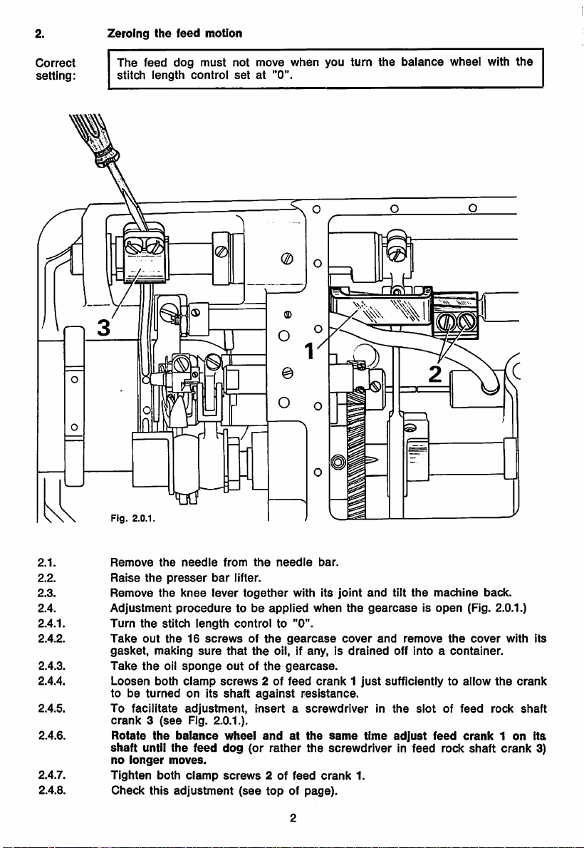
2.
Zeroing
the
feed
motion
Correct
setting:
The
stitch
feed
length
dog
must
control
not move
setat"0".
when
you turn
%
the
balance
wheel with
the
2.1.
2.2.
2.3.
2.4.
2.4.1.
2.4.2.
2.4.3.
2.4.4.
2.4.5.
2.4.6.
2.4.7.
2.4.8.
Fig. 2.0.1.
Remove
Raise
Remove
Adjustment
Turn
Take
gasket,
Take
Loosen
tobeturnedonits
To
crank3(see
Rotate
shaft
no
Tighten
Check
the
needle
the
presser
the
knee
proceduretobe
the
stitch
iength
out
the16screwsofthe
making
the
oil
sponge
both
clamp
faciiitate
longer
the
until
both
this
adjustment,
Fig. 2.0.1.).
balance
the
feed
moves.
clamp
adjustment
sure
from
the
bar
iifter.
lever
together
controlto"0".
that
the
outofthe
screws
2 of
shaft
against
insertascrewdriver
wheel
andatthe
dog
(or
screws
2 of
(see
topofpage).
needle
with
applied
gearcase
oil, if
gearcase.
feed
rather
feed
bar.
its
joint
when
the
cover
any,isdrained
crank1just
resistance.
same
the
screwdriver
crank
1.
and
tilt
the
machine
gearcaseisopen
and
remove
off
intoacontainer.
sufficientlytoallow
in
the
slotoffeed
time
adjust
feed
in feed rock
back.
(Fig. 2.0.1.)
the
cover
crank1on
shaft
the
rock
crank
with
crank
its
shaft
Its
3)
Page 5
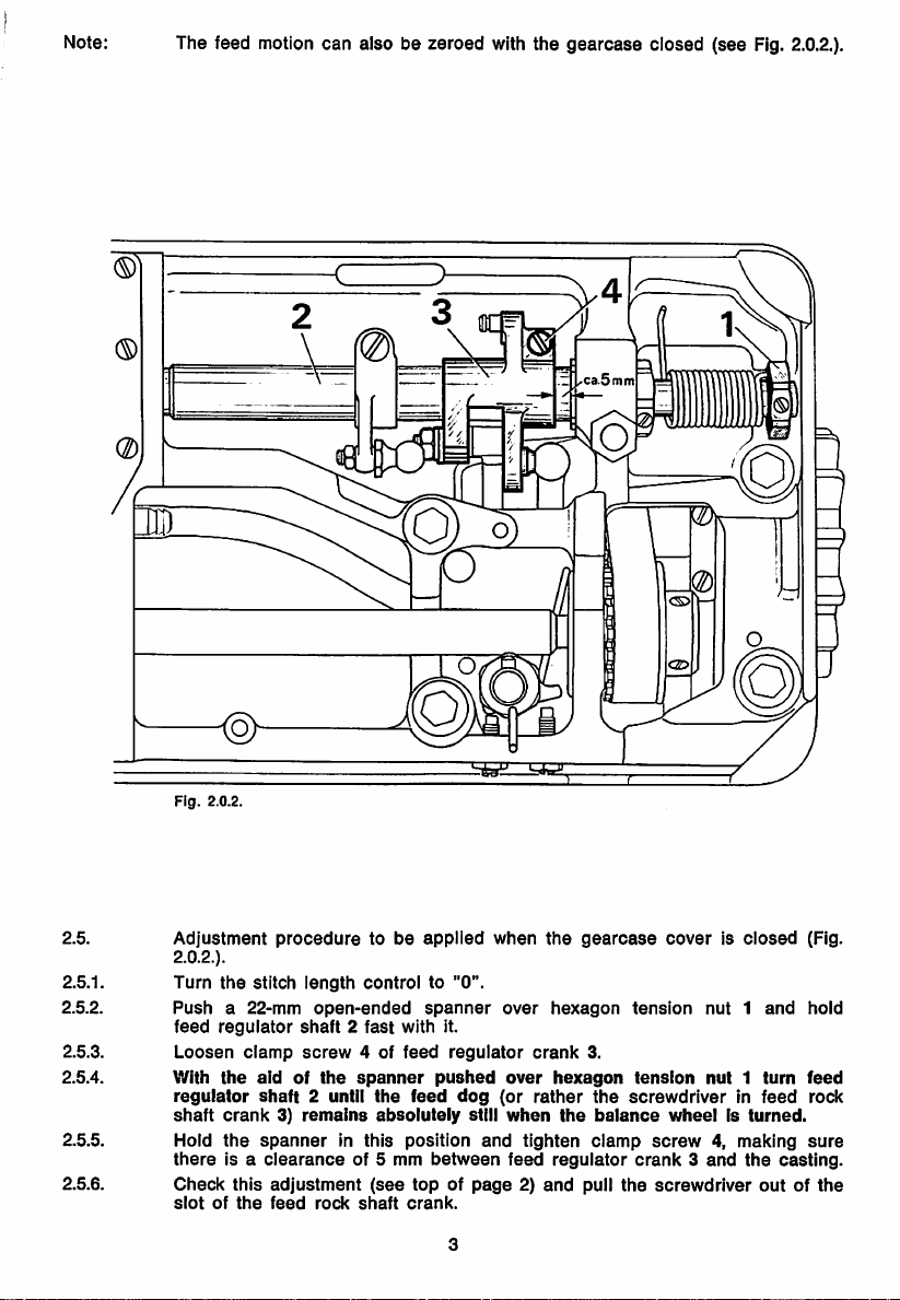
Note:
The feed motion
can
also be zeroed with the
gearcase
ciosed (see Fig.
Qb
2.O.2.).
Fig.
2.5.
2.5.1.
2.5.2.
2.5.3.
Adjustment
2.O.2.).
Turn
Pusha22-mm
feed
Loosen
2.5.4. With
regulator
shaft
2.5.5. Hold
there
2.5.6.
Check
slotofthe
2.0.2.
proceduretobe
the
stitch
iength
regulator
the
crank3)remains
the
is a
this
shaft2fast
clamp
screw
aidofthe
shaft
2 until
spannerinthis
clearance
adjustment
feed
controlto"0".
open-ended
4 of
spanner
the
absolutely
of 5 mm
(see
rock
shaft
applied
spanner
with
feed
feed
position
it.
regulator
pushed
dog
still
between
when
and
over
over
(or
when
tighten
feed
topofpage2)and
crank.
the
hexagon
crank
hexagon
rather
the
regulator
^ r
gearcase
tension
3.
tension
the
screwdriverInfeed
balance
clamp
screw4,making
crank3and
pull
the
coverisclosed
nut1and
nut1turn
wheelIsturned.
the
screwdriver
(Fig.
hold
feed
rock
sure
casting.
outofthe
Page 6
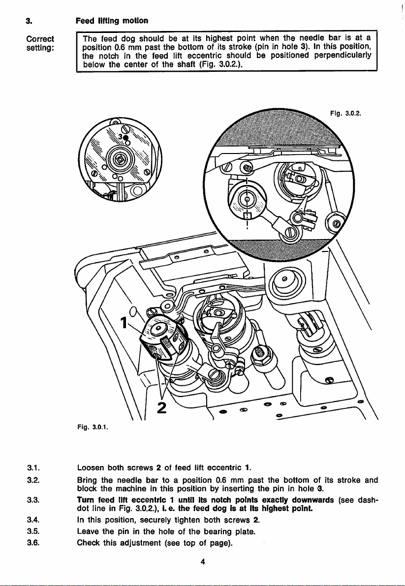
Feed
lifting
motion
Correct
setting:
The feed dog should be at Its highest point when
the
needle bar Is at a
position 0.6 mm past the bottom of its stroke (pin in hole 3). In this position,
the
notchinthe
below
the
feed
centerofthe
lift
shaft
eccentric
(Fig. 3.O.2.).
should
be
positioned
perpendicularly
I."
Fig.
3.0.2.
3.1.
3.2.
3.3.
3.4. In
3.5.
3.6.
Fig.
Loosen
Bring
block
Turn
dot
this
Leave
Check
3.0.1.
both
screws2of
the
needle
the
machineInthis
feed
lift
line
eccentric
In Fig. 3.O.2.), I. e.
position,
the
pin In
this
adjustment
bartoa
securely
the
holeofthe
feed
lift
eccentric
position
0.6 mm
positionbyInserting
1 until its
the
tighten
feed
notch
dogisat
both
bearing
(see
topofpage).
points
screws
plate.
1.
past
its
2.
the
the
exactly
highest
bottom
pin In
of its
hole
3.
downwards
point.
stroke
(see
and
dash-
Page 7
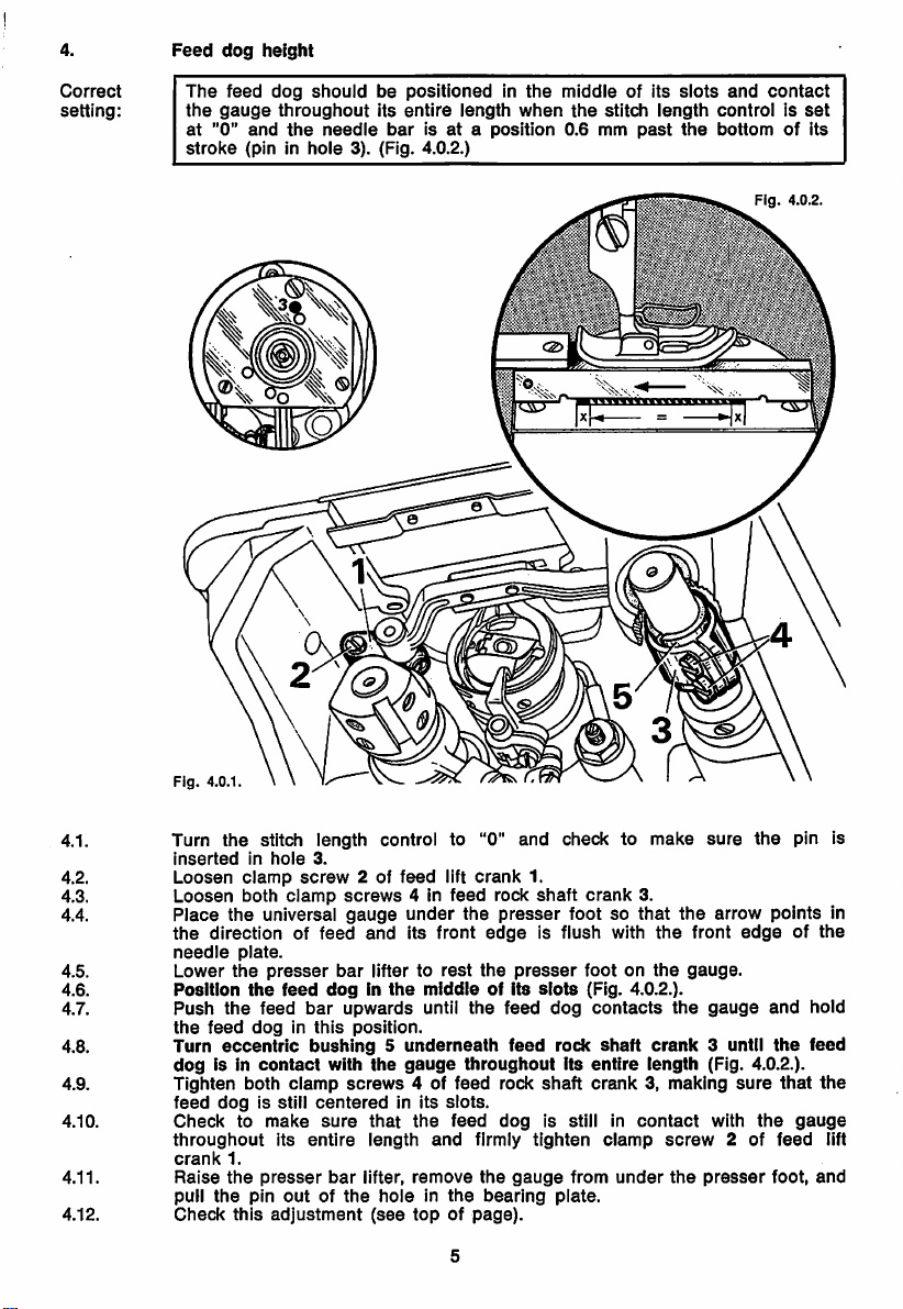
Feed
dog
height
Correct
setting:
The
the
at
"0"
stroke
feed
gauge
and
(pin in
dog
should
throughout
the
needle
hole
be
positionedinthe
its
entire
barisataposition
3). (Fig. 4.0.2.)
length
when
middle
the
0.6 mm
of its
stitch
past
slots
length
the
and
contact
controlisset
bottom
of its
Fig.
4.0.2.
4.1. Turn the stitch length control to "0" and check to make
4.2.
4.3.
4.4.
inserted
Loosen
Loosen
Place
the
4.5.
4.6.
4.7.
needle
Lower
Position
Push
the
4.8. Turn
dog
4.9. Tighten both
4.10.
4.11.
4.12.
feed
Check
throughout
crank
Raise
pull
Check
in
hole
clamp
both
the
universal
direction of
plate.
the
presser
the
feed
the
feed
feed
doginthis
eccentric
is in
contact
dog
is still
to
make
its
1.
the
presser
the
pin
outofthe
this
adjustment
3.
screw
2 of
screws
gauge
and
bar
lifter to
upwards
position.
feed
4 in
under
its front
middleofits
until
ciamp
feed
doginthe
bar
bushing5underneath
with
the
screws
that
length
lifter,
holeinthe
(see
gauge
4 of feed rock
the
remove
topofpage).
clamp
centeredinits
sure
entire
bar
lift
feed
the
rest
the
throughout
slots.
feed
and
crank
rock
presser
edge
the
dog
firmly
the
bearing
1.
shaft
is flush with
presser
slots
feed
dog
feed
rock
shaft
is still in
tighten
gauge
plate.
crank
foot so
footonthe
(Fig. 4.O.2.).
contacts
shaft
its
entire
crank
clamp
from
under
3.
that
the
the
crank
length (Fig. 4.O.2.).
3, making
contact
screw
the
sure
the
front
gauge.
3 until
presser
the
arrow
edgeofthe
gauge
sure
with
the
2 of
pin is
points
and
the
that
gauge
feed
foot,
in
hold
feed
the
lift
and
Page 8
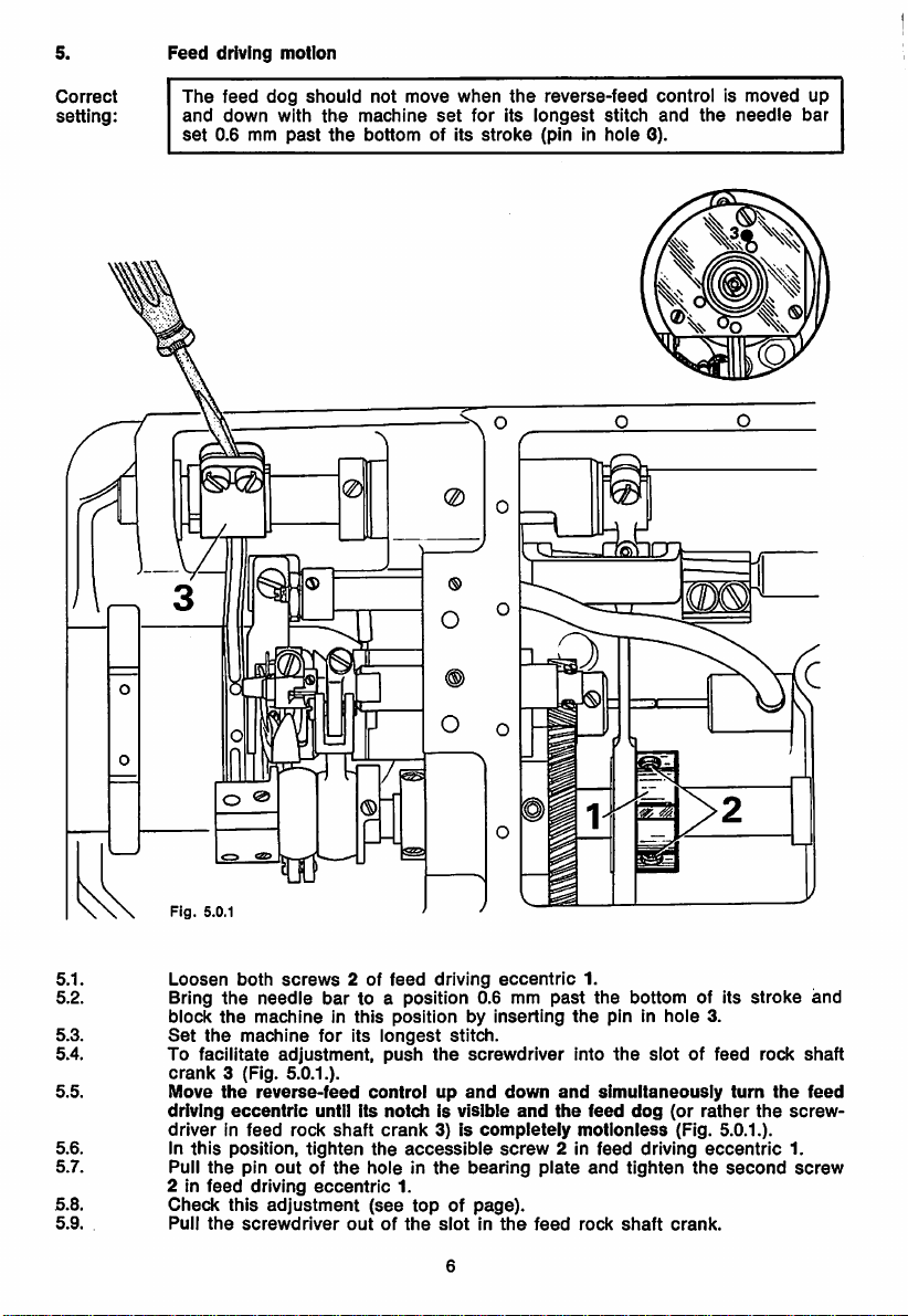
5.
Feed
driving
motion
Correct
setting:
The
and
set
feed
down
0.6 mm
dog
with
past
should
the
the
QC
not move
machine
bottom
set
of Its
when
for
stroke
the
reverse-feed
Its
longest
(pin In
stitch
hole
control
and
3).
Is moved up
the
needle
bar
6.1.
5.2.
5.3.
5.4.
5.5.
5.6.
5.7.
5.8.
5.9.
Loosen
Bring
block
Set
both
the
needle
the
machineInthis
the
machine
To facilitate
crank
3 (Fig. 5.0.1.).
Move
the
driving
reverse-feed
eccentric
driverInfeed
In
this
position,
the
feed
this
the
pin
driving
screwdriver
Pull
2 In
Check
Pull
screws
bar
for
adjustment,
until its
rock
shaft
tighten
outofthe
eccentric
adjustment
2 of
feed
to a
driving
position
positionbyinserting
Its
longest
push
stitch.
the
controlupand
notch
is visible
crank
3) is
the
accessible
holeinthe
1.
(see
topofpage).
outofthe
slotInthe
eccentric
0.6 mm
screwdriver
down
and
completely
screw
bearing
plate
feed
1.
past
the
the
Into
and
simultaneously
the
feed
motionless
2 In
feed
and
rock
bottom
pin In
the
dog
driving
tighten
shaft
of Its
hole
3.
slotoffeed
(or
rather
(Fig. 5.0.1.).
eccentric
the
second
crank.
turn
stroke
rock
the
the
and
shaft
feed
screw
1.
screw
Page 9
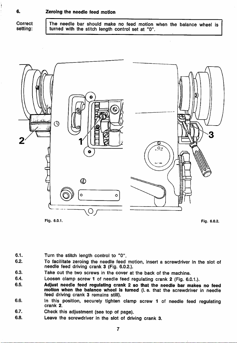
6.
Zeroing
the
needle
feed
motion
Correct
setting:
The
turned
needle
with
bar
the
should
stitch
make
length
no feed motion when
control
setat"0".
the
balance
wheel is
Fig.
6.0.1.
6.1. Turn
6.2. To facilitate
6.3.
needle
Take
the
stitch
feed driving
out
the
length
zeroing
two
screwsinthe
controlto"0".
the
needle
crank
3 (Fig. 6.O.2.).
feed
motion,
coveratthe
insertascrewdriverinthe
backofthe
machine.
6.4. Loosen clamp screw 1 of needle feed regulating crank 2 (Fig.
6.5. Adjust
motion
feed
needle
when
driving
feed
regulating
the
balance
wheelisturned
crank3remains
crank2so
still).
that
(I.e.
the
that
needle
bar
the
screwdriverinneedle
Fig.
6.0.2.
slot
6.0.1.).
makesnofeed
6.6. In this position, securely tighten clamp screw 1 of needle feed regulating
crank
2.
6.7. Check this adjustment (see top of page).
6.8. Leave the screwdriver in the slot of driving crank 3.
of
Page 10
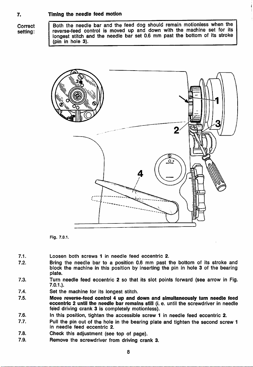
7.
Timing
the
needle
feed motion
Correct
setting:
Both the needle bar and
reverse-feed control Is moved up and down with the machine
the
feed dog should remain motionless when the
set
for Its
longest stitch and the needle bar set 0.6 mm past the bottom of Its stroke
(pin In
hole
3).
Fig. 7.0.1.
7.1.
7.2. Bring
7.3.
7.4.
7.5.
7.6. In
Loosen
block
the
plate.
Turn
needle
7.0.1.).
Set
the
Move
reverse-feed
eccentric
feed
driving
this
both
screws
the
needle
machineInthis
feed
machine
2 until
crank
position,
7.7. Pull the pin out of
in
needle
feed
eccentric
7.8.
7.9. Remove
Check
this
the
adjustment
screwdriver
1 in
needle
feed
eccentric
bar
to a
position
0.6 mm
positionbyInserting
eccentric2so
for its
longest
control4up
the
needle
3 Is
completely
tighten
the
the
hole In the bearing plate and tighten
2.
(see
from driving
that
Its
stitch.
and
bar
down
remains
motionless).
accessible
topofpage).
crank
8
slot
and
still (I. e. until
screw
2.
past
the
the
pin In
points
forward
simultaneously
1 In
needle
3.
bottom
the
of Its
3 of
(see
turn
stroke
the
arrow
needle
hole
screwdriverInneedle
feed
eccentric
the
second
and
bearing
In Fig.
feed
2.
screw
1
Page 11

8.
Centering
the
needleinthe
needle
hole
Correct When the feed dog is at Its highest point, the needle should be positioned
setting; exactly In the middle of the needle hole both lengthwise and crosswise
(Fig. 8.O.3.).
Ffg.
8.0.3
Fig.
8.0.1.
Fig.
8.0.2.
8.1. Bring
8.2. Insert a new System 134 needle Into the needle bar and push It up as far
8.3.
It will
Turn
the
the
go,
needle
making
stitch
bar
sure
length
to Its
its
control
highest
long
groove
to "0".
point
and
faces
remove
toward
the
the
presser
left.
foot.
as
8.4. Loosen clamp screw 1 of needle feed driving crank 2 (Fig. 8.0.1.).
8.5. Loosen screw 3 In the lug of the needle bar frame (Fig.
8.O.2.).
8.6. Rotate the balance wheel and simultaneously adjust the position of needle bar
frame 4 until the needle enters
8.7. Bring
the
wiseofthe
the
needle
needle Is
centered
sewing
bar
to Its lowest point
exactly In
direction (Fig.
the
needle hole In the feed dog.
and
adjust
the
needle hole, both lengthwise
needle
8.O.3.).
bar
frame 4sothat
and
cross
8.8. In this position, tighten clamp screw 1 In driving crank 2.
8.9.
8.10. Check this adjustment
Turn
the
stressInneedle
balance
wheel
bar
frame4,and
a few
(see
top of page).
turnstoensure
tighten
screw
that
3.
the
needle
barIsnot
under
Page 12

Eliminating
feed
differences
Correct
setting;
With
the machine set for Its longest stitch, both the feed dog and the needle
should
turned.
make
feed
strokes
of the same
length
when
the
balance
(2)
wheel
is
9.1.
9.2.
9.3.
9.4.
9.5.
9.6.
Fig.
9.0.1.
Set
the
machine
Loosen
Move
the
it in
Tighten
Check
adjust,Ifnecessary.
Check
stud
the
nut1on
hinge
toward
opposite
nut1on
whether
this
stud
the
adjustment
for Its
hinge
2 in
the
regulating
direction
hinge
needle
longest
stud
the
stud
(see
stitch.
2 of
regulating
forkofregulating
shaft
increases
2.
feed
is still
topofpage).
10
crank
decreases
it.
zeroed
3.
crank3,as
the
needie
properly
appropriate.
feed
stroke,
(see
Chapter6)and
Moving
moving
Page 13

10.
Hook
shaft
bearing
and
gear
play
Correct
setting;
There should be a clearance of 0.3 mm between sewing hook and oil
distributor ring when the hook point is opposite the needle and both
parts
are
play
0.1 mm
between
the
apart
(Fig. 10.0.2.). Also
gears.
Fig.
10.0.2
there
should
be a minimum of
these
C®
10.1.
10.2.
10.3.
10.4.
10.5.
10.6.
10.7.
10.8.
10.9.
10.10.
10.11.
10.12.
10.13.
Fig,
10.0.1
Remove
Loosen
of oil
Loosen
the
Turn
10.0.1.) Is
play
Loosen
Push
Bring
strike
Reposition
0.4 mm
turn
ring.
With
Loosen
Reposition
spur
needle
screw
distributor
alien
bedplate
eccentric
visible
nor
stand
both
the
sewing
the
needle
the
sewing
between
the
bearing
the
bearinginthis
both
gear.
plate
1 of oil
ring
screw
(Fig. 10.0.2.).
hook
from
too
close
hook
set
hook
bar
hook.
hook
shaft
hook
and
screws
spur
gear
and
regulating
3.
4 of
eccentric
shaft
below
together.
screws
against
to its
bearing
point
that
position,
8 in
7 on Its
feed
dog,
valve2and
bearing5so
and
6.
the
lowest
5 in
and
needle.
the
hook
large
tighten
spur
shaft
turn
the
stitch
length
the
5 on
recess
have
control
oil
hook
the
two
shaft
that
swivel
spur
bearing
the
gears
oil distributor ring.
point,
making
the
remainsincontact
gear
casting
Make
alien
7.
sure
until
sure
screw
that
the
there
however
with
4.
until It Is exactly in line with
to "0".
tubeofvalve2out
the
top
surface
(see
arrow in Fig.
neither
too
much
needle
does
not
is a
clearance
that
you do not
the
oil
distributor
the
small
Tighten both screws 8 securely, making sure that the second screw of spur
gear 7 — as
of
the
shaft.
seen
in its direction of rotation — is positioned in the groove
Do not tighten hook set screw 6 as yet and leave the oil tube swivelled away.
11
of
of
Page 14

11.
Needle
bar
height,
hook
timing
and hook-to-needle clearance
Correct
setting:
The needle bar should be set
eyeIspositioned
11.0.2.).
(pin
The
In hole 4), the hook-to-needle clearance
0.8
mm
amountofneedle
vertically
below
rise
so that the top edge of the needle
the
bottom
requiredtoform
edge
0.1
mm.
of the
the
hook
loopIs1.8
point
Fig. 11.0.2
(Fig.
mm
Fig.
11.0.1.
11.1.
11.2. Make
11.3. Loosen both clamp screws 2 In needle bar connecting stud 1.
11.4.
11.5. Move the needle bar up or down until there is a clearance of 0.8 mm between
Bring
the
needle
though
machine In this position by Inserting the pin In hole 4.
sure
that the
the
stitch length control Is
sure
bar to a
point
needle
1.8
mm
does not
set
past the
strike
at "0".
bottomofIts
the
sewing
stroke,
hook.
making
Block
the
Turn the sewing hook on Its shaft until Its point Is exactly opposite the center
lineofthe
the top edge of the needle eye and the bottom edge of the hook point
11.0.2.);
needle
needle.
(Fig.
the hook point Is now positioned approximately In the middle of the
scarf.
11.6. In this position, tighten both clamp screws 2, making sure that the needle set
11.7.
Adjustthe sewing hook
exactlytothe
right.
until
there is a clearance of
0.1
mm
between Its point
screw
points
and the needle (center of scarf); make sure that the position finger Is still In
the
11.8. In this position, tighten
11.9.
11.10.
slotofthe
Pull the pin out of the hole In the bearing plate and tighten the second hook
set
screw.
Check
this
bobbin
adjustment
case.
the
accessible
(see
topofpage).
hook
set
screw.
12
Page 15

12.
Vertical position of bobbin
case
opener
Correct
setting:
When at its left point of reversal, bobbin
case
opener finger 3 stiouid be
positioned vertically so that it is exactly opposite the lug of bobbin
base
4 (Fig. 2.O.2.).
Fig.
12.0.2
m
case
12.1.
12.2.
12.3.
11.4.
12.5.
Fig.
12.0.1.
Loosen
Turn
the
screw
balance
1 of
wheeltobring
Turn bushing 2 until
case
base
4.
In
this
Check
position,
this
tighten
adjustment
eccentric
opener
screw
(see
bobbin
the
case
opener
finger 3 Is exactly
1 of bushing 2.
top
of page).
13
opener
finger
shaft
bushing 2.
to its left
opposite
point
the
lug of bobbin
of reversal.
Page 16

13.
Correct
setting:
Positionofbobbin
There
should be a
1 and bobbin
is at
the
position finger 6 and bobbin case base 5
case
opener
clearance
case
base 5 (Fig.
left of its stroke,
of 0.8 mm
there
13.0.2.).
Furthermore, when opener finger 1
shouldbea
between
clearance
(Fig.
bobbin
13.0.3.).
lug on collar 4 should be up against the stop of opener
13.0.1.).
case
opener
finger
of 0.3 mm
between
In this position, the
finger1(Fig.
Fig.
13.0.3.
13.1.
Fig.
Loosen
13.0.2.
screw3of
collar
4.
13.2. Loosen clamp screw 2 of opener finger 1 just sufficiently to allow it to be
13.3. Reposition opener finger 1 on its shaft until there is a clearance of 0.8 mm
turnedonIts
betweenitand
13.4. Rotate
13.5. Turn
opener
finger 6
opener
13.6. In
13.7.
13.8. In
13.9.
this
Push
collar
the
stopofopener
this
Check
shaft
against
the
bobbin
balance
wheel until
finger 1 until
and
the right wall of the position siot In the bobbin
finger 1
position,
position,
this
contacts
tighten
4 up
against
tighten
adjustment
finger
resistance.
case
base
there
the
clamp
opener
1.
screw
(see
topofpage).
5 (Fig. 13.0.2.).
opener
finger 1 is at
is a
clearance
lug of bobbin
screw
2 of
finger 1
3 of
14
and
collar
case
opener
turnitso
4.
the
left of its
stroke.
of 0.3 mm between position
case
base
base
5 (Fig. 13.0.3.).
finger 1.
that
its lug is up
when
against
Page 17

14.
Correct
setting:
Timing
When
in hole 4),
the
the
bobbin
needle
opener
case
bar
finger 3
opener
has
risen
should
1.8 mm from
be at
the
the
bottom
right of its
of its
stroke
stroke
(pin
(Fig. 14.0.2.).
Fig.
14.0.2.
14.1.
Loosen
both
screws
2 of
bobbin
case
opener
eccentric
1.
14.2. Bring the needle bar to a position 1.8 mm past the bottom of its stroke and
block
the
machine in
this
position by inserting
the
pin in
hole
4.
14.3. To facilitate determining the exact point of reversal insert a small screwdriver
in
the
slotofthe
14.4. Turn
opener
14.5. In this position, tighten
14.6. Pull the pin out of the hole in the bearing plate and tighten
2
also.
14.7. Puii
of
the
page).
screwdriver
clampofopener
eccentric 1 until
the
outofthe
finger
opener
accessible
clamp
15
3.
finger 3 is at its right point of reversal.
screw
2 of
opener
eccentric 1.
the
slot
and
check
this
second
adjustment
(see
screw
top
Page 18

15.
Correct
setting;
Oil
tube
Oil
tube1should
15.0.2.).
In oil
distributor
m
ring
be
positionedinthe
Fig.
15.0.2.
hole
of oil
distributor
ring 2 (Fig.
Fig.
15.0.1.
15.1.
Insert
If
necessary,
oil
tube
1 into
turn
the
the
oil
15.1.1. On subcl. -900 machines
have loosened the three
15.2. Tighten
screw
3 of oil regulating valve 4 (Fig. 15.0.1.).
hole
of oil distributor ring 2
distributor
the
screws
ring
accordingly.
oil distributor ring cannot be turned until you
on the front
16
side
(see
arrow in Fig. 15.0.2.);
of the hook shaft bearing.
Page 19

16.
Oil
check
valve
Correct
setting:
There
shouldbea
centrifugal
governor
clearance
and
push
of 1.0 mm
rod 4 of
between
the
oil check valve (Fig. 16.0.2.).
actuating
rod 3 of
Fig. 16.0.2
the
Fig.
16.0.1
16.1.
16.2. Push actuating rod 3 to
Loosen
screw1of
oil
check
valve
2.
the
leftasfarasit will go.
16.3. Push push rod 4 into oil check valve 2 until a resistance is felt.
16.4.
16.5. In this position, tighten
16.6. Check
16.7. Soak the oil sponge with oil and replace it in the
16.8. Clean
16.9. Replace the
Reposition oil check valve 2 until there is a clearance of 1.0 mm between
actuating
rod 3
this
and
adjustment
push
(see
rod 4.
screw
1 of oil check valve 2.
top
of page).
gearcasesothat
recessIsat
legs,
the
the
gasket
tightening
bottom
faceonthe
gearcase
the
screwsofthe
left
and
the
oil
gearcase
tubeisplacedontop
and
the
gasketofthe
of it.
cover and simultaneously screw on the two machine
cover
crosswise.
17
gearcase
its large
cover.
Page 20

17.
Hook
lubrication
Correct
setting:
After
of oii
cutout
the
shouid
above
machine
appear
the
has
hook
runatfuli
on a
pieceofpaper
raceway.
speed
for
about
placed
ten
seconds,
over
the
a fine
needle
trace
plate
17.1.
17.2.
17.3.
17.4.
17.5.
17.6.
17.7.
17.8.
Fig
Turn in regulating
then
back
about
Switch on the machine
Turn
regulating
Let
the
machine
Placeapiece
Let
the
of oii
If
oilIsemitted,
machine
has
appearedonthe
too
much oil Is emitted, turn regulating
screw
three
screw
run
about
of white
run
turnitout
1 of oii regulating valve 2 as farasit will go,
turns.
and
run it until the sewing hook
1 in
paper
about
somewhat.
completely
one
over
ten
paper
minute.
the
seconds.
opposite
and
needle
Check this adjustment (see top of page).
18
then
plate
Then
the
screw
starts
out
half a turn.
cutout.
checktosee
hook
raceway.
1 In a little; or If
emitting oil.
if a
fine
too
and
trace
little
Page 21

18.
Clearance
between
presser
foot
and
needle plate
Correct
setting:
When
between
the
presser
presser
bar
lifter Is
raised
foot and needle plate (Fig. 18.0.2.).
there
shouldbea
clearance
of 7.0 mm
Fig.
18.0.1
Fig.
18.0.2
19
Page 22

18.1.
Replace
the
feed
dog.
18.2. Screw on the needle plate, making sure that the feed dog moves freely In
Its
slots.
18.3.
18.4. Lower the
18.5. Reduce the
18.6.
18.7. Loosen
18.8.
18.9.
18.10.
18.11.
18.12.
18.13. Rotate
Replace
the
presser
until
the
presser
Push
the
rear
7-mm-thlck
until It Is
the
clamp
the
machine
Raise
presser
Turn
the
balance
Adjust
the
In
Its
needle
Press
presser
and
tighten
Remove
needle
the
plate.
the
the
needle
paralleltothe
presser
foot.
foot onto
pressure
of the
foot Is
bladeofthe
positioned
screw
arm.
positionofthe
hole.
clamp
gauge
balance
holeofthe
3 of
bar
lifter 1.
wheel
bar
lifting
screw3securely.
from
wheel to
edgesofthe
the
needle plate by operating
presser
pressed
against
bar
the
universal
below
the
presser
until
presser
bracket4downwards
under
presser
bar
lifting bracket 4 Inside
the
needleIsdownInthe
footsothat
the
presser
see
whether
foot, I. e.
feed
dog.
presser
bar lifter 1.
by turning out regulating screw 2
needle
plate only slightly.
gauge
under
the
presser
foot fulcrum.
the
onto
foot
the
needleIscentered
whether
presser
needle
needleIscentered
the
raised
and
lower
the
the
sidesofthe
the
hole.
front
lifting
foot
foot from
onto
correctly In
foot
end
exactly
lever
the
are
of
5
18.14.
Check
this
adjustment
(see
topofpage).
20
Page 23

19.
Tension
release
mechanism
Correct
setting:
When
0.5 mm
the
apart
presser
(Fig. 19.0.2.).
•jp.:
bar
lifter is
raised
both
tension
/
discs
shouldbeat
Fig.
least
19.0.2
Fig. 19.0.1.
19.1.
19.2.
19.3.
Operate
Loosen
Adjust
between
presser
screw2of
tension
both
tension
bar
tension
reiease
18.4. In this position, tighten
18.5.
19.6. Check
When
fully
the
presser
activated.
this
adjustment
foot is lowered
lifter 1toraise
release
lever3so
discs
when
screw
2 of tension release lever 3 securely.
(see
top
of page).
21
lever
that
the
onto
the
there
presser
the
presser
3.
is a
needle
foot.
clearanceofat
bar
lifter is
plate,
raised.
the
tension
least
0.5
should
mm
be
Page 24

20.
Thread ched< spring
and
thread
regulator
Correct
setting:
The stroke of thread check spring 4 should be about 7.0 mm
The
positionofthread
regulator
6 is dependent on the
(Fig.
type
of thread and
20.0.2.).
material used and should be adjusted according to the appearance of the
seam.
0
20.1.
20.2.
20.3.
20.4.
20.5.
20.6.
20.7.
Loosen
tension
Turn
about
In
them
thread
Check
Loosen
Push
In
dependent
accordingtothe
both
barrel
tension
7.0
mm (Fig. 20.0.2.).
this
position,
alternately).
check
this
both
thread
this
position,
spring
adjustment
screws
regulator
on
screws
3 tobeturnedinthe
barrel
1 of
thread
3 until
the
tighten
both
Special
forashorterorlonger
5 of
sewing
(see
topofpage).
thread
screws
6 upasfarasit willgo(Fig. 20.0.1.).
tighten
the
both
type of
appearance
screws5.(The
thread
of
tension
tension
strokeofthe
1 of
tension
operations
regulator
the
22
and
seam.)
6.
material
flange2just
flange.
thread
flange2evenly
may
makeitnecessarytoset
stroke.
position of
used
sufficientlytoallow
check
the
thread
and
shouldbeadjusted
spring
amounts
(by
tightening
regulator
to
the
is
Page 25

21.
Knee
lever
rest
position
Correct
setting;
When at rest, knee lever connecting rod 1 should extend at right angles to
the front
edge
of the bedplate (Fig. 21.0.2.).
Fig.
21.0.2
Fig.
21.0.1.
21.1.
21.2.
Raise
Push
and
the
presser
knee
lever
turn
It slightly until It
connecting
21.3. Loosen locknut 4 of
21.4. Turn
stop
front
screw
edgeofthe
to
the
21.5. In this position, lock
21.6. Pull
knee
lever
connecting
foot.
stop
5 until
stop
rod 1
snapsInplace.
screw
knee
bedplate.
screw
rod 1
together
5 (Fig. 21.0.1.).
lever
5 by tightening nut 4.
out
23
with joint 2 on
connecting
of joint 2.
rod 1
extendsatright
knee
lever
shaft
angles
3
Page 26

22.
Correct
setting:
Knee
lever
play
When
the presser
positioned
1.3mmbetween
below
footIsdown
the
needle
lifting
lever 1 and
on the
plate,
there
lifting
needle
should
bracket 2
plate and the
be a
clearanceofabout
(Fig.
22.0.2.).
feed
Fig.
dog Is
22.0.2
O
Fig.
22.0.1.
22.1. Lower the feed dog below the needle plate and let the presser foot down on
22.2. Loosen both clamp screws 4 of crank 3 on the vertical knee lever shaft.
22.3.
22.4.
22.5. Pull out the gauge and Insert the knee lever connecting rod Into its joint.
22.6.
22.7. Pull
the
needle
plate.
Adjust crank 3 so that there Is a clearance of about 1.3 mm between
lever 1
and
lifting bracket 2. (Use
the
gauge
for this adjustment.)
lifting
In this position, tighten both clamp screws 4, making sure the vertical knee
lever
shaft
Check
the
hasnoend
this
adjustment
knee
lever
play.
(see
connecting
topofpage).
rod
out
24
of Its
socket.
Page 27

23.
Adjusting
the
knee
lever
motion
Correct
setting:
When
the knee lever is at the extreme right of its travel, the presser foot
should have risen at least 7.0
mm
above the needle plate and the presser
bar lifter should have dropped down by its own weight.
Fig.
23.0.1.
L J
II
23.1.
Insert
the
knee
lever
F .
23.0.2
connecting
rod in its
K.;i
socket.
•
23.2. Loosen iocknut 1 of stop screw 2 (Fig. 23.0.1.).
23.3.
23.4. Raise the presser bar
Turn
stop
screw2out
a few
turns.
lifter,
place the 7-mm-thick blade of the universal gauge
under the presser foot and lower the presser bar lifter again (Fig. 23.0.2.).
23.5.
23.6. Hold the knee lever in this position and turn In stop
23.7. Pull out
Push the knee lever to the right
this motion, the
go, then
out
the
presser
foot must not yet lift off the gauge.
again by half a turn. Lock
gauge
and
draw
the
until
a noticeable resistance is felt; during
screw2as
stop
screw
2 by tightening nut 1.
knee
lever
out
of its socket.
farasIt will
23.8. Let the machine down again, replace the knee lever and ched< this adjustment
(see
topofpage).
25
Page 28

24.
Bobbin
winder
When the bobbin winder Is engaged, the winder spindle should be driven
reliably;
must
not
when
contact
the
bobbin
drive
wheel
winder
1.
is disengaged,
however,
friction
wheel
The bobbin winder should stop automatically when the thread wound on the
bobbin has reached a point about 1.0mmbelow Its
rim
(Fig.
24.0.2.).
Fig.
3
24.0.2.
24.1.
24.2.
24.3.
24.4.
24.5.
24.6.
24.7. If
24.8. If
24.9. If
24.10.
Fig.
24.0.1
Take
out
the
three
screws
Raise
the
presser
Loosen
Set
drive
both
wheel1so
driven reliably
when
the
bobbin
Tighten
Placeabobbinonthe
and
machine.
stud
full
the
Check
both
engage
the
bobbin
6 In
the
bobbinistoo
enough,
the
thread
machine
this
stop
bar
screws
when
winderisdisengaged.
screws
the
bobbin
winder
latch
pushitaway
piles
up on
arm
accordingly.
adjustment
retaining
lifter
and
2 In
drive
wheel
close
to
bobbin
drive
friction
wheel
spindle,
the
2 of
winder
winderbypushing
stops
too
4.
full,
(see
earlyornotatall,
push
regulating
from
the
one
sideofthe
topofpage).
26
the
rear
arm
engage
the
bobbin
1.
wheel3that
winderisengaged,
1.
thread
the
against
stud6toward
bobbin.
Then
bobbin,
cover.
winder.
machine
Its
loosen
tighten
adjust
friction
but
spindle.
screw
the
screw
wheel3will
will
notbedriven
for
bobbin
Then
5 of
bobbin,
5 of
the
thread
winding
start
regulating
if it is
stop
latch
guide
be
the
not
4.
on
Page 29

25. Presser foot pressure and final worksteps
25.1.
Replace and screw on the face cover, both rear arm covers and the belt guard.
25.2. Thread the machine, place a piece of fabric under the presser foot and lower
the
25.3.
25.4.
presser
Turn in pressure regulating screw 7
material Is
Test-sew
foot
ensured
on
the
onto
it.
evenattop
machine.
speed.
(Fig.
25.0.1.)
until proper feeding of the
27
Page 30

Contents
1.
Preparations
2.
Zeroing
3.
Feed
4.
Feed
5.
Feed
6.
Zeroing
7.
Timing
8.
Centering
9.
Eliminating
10.
Hook
11.
Needle
12.
Vertical
for
adjusting
the
feed
motion
lifting
motion
dog
height
driving
motion
the
needle
the
needle
the
needleinthe
feed
differences
shaft
bearing
bar
height
positionofbobbin
feed
motion
feed
motion
and
gear
and
hook-to-needle
needle
play
case
....
....
hole
....
opener
.
clearance
.
Positionofbobbin
13.
14.
Timing
15. Oil
16.
17.
Hook
18.
19.
Tension
20.
21.
22.
23.
Adjusting
24.
25.
the
tube
Oil
check
lubrication
Clearance
Thread
check
Knee
lever
Knee
lever
Bobbin
Presser
winder
foot
bobbin
and
valve
between
release
rest
play
the
pressure
oil
distributor
mechanism
spring
position
knee
case
case
presser
and
lever
and
opener
opener
ring
foot
thread
motion
final
....
....
....
and
needle
regulator .
....
worksteps
plate
.
28
Page 31

Nr.
236-12-13285
engl.
1072
CMMTf
PrintedinGermany
 Loading...