

Page 1
m
®
PFAFF
CIfafD
Instruction
Book
Page 2
(PFAFP
f
469
High-Speed
Differential-Feed
Lockstitch
Instruction
Sewing
Machine
Book
G-M
PFAFFAG
KAISERSLAUTERN
BRANCH
Page 3
Foreword
The
scope
of this book is confined to such instructions as are conditioned by variations in the
design of the Pfaff 469 high-speed differential-feed sewing machine as compared with other
Pfaff
high-speed
An
outstanding
bearingsinthe
Another salient feature is the arrangement of the feed driving and feed lifting eccentrics on the
bottom
rather
belt
and
drives
in an oiltight gear case and are lubricated by an oil-soaked foam plastic sheet. The assemblies
controlling the differential-feed are disposed on two shafts inside and outside the gear case.
The sewing hook is lubricated by means of a gravity lubrication system incorporating a
centrifugal
Since the arm shaftisbeltedto the
the
V-belt.
Additional features of this
forward-reverse
Operators will like the modern functional design and the stream-lined belt guard which is
attachedtothe
feature
machine
than
the
switch.
seamers.
the
hook
feed
control,
machine
ofthe
Pfaff
469
isthe
incorporationdfsealed-for-life
arm
and
the
needle
head.
arm
shaft.
The
bottom
shaftisdriven
shaft
by means of helical gears. These driving elements are
motor,
the
new
high-speed
built-in
arm.
bobbin
seamer
winder
'
from
the
machine
c^n be tilted back without
are a novel stitch length control,
and
built-in
lifting lever. •
arm
ball
and
shaftbya
needle
cleated
enclosed
remoylng
separate
G.M.PFAFF
AG
Page 4
R
8766
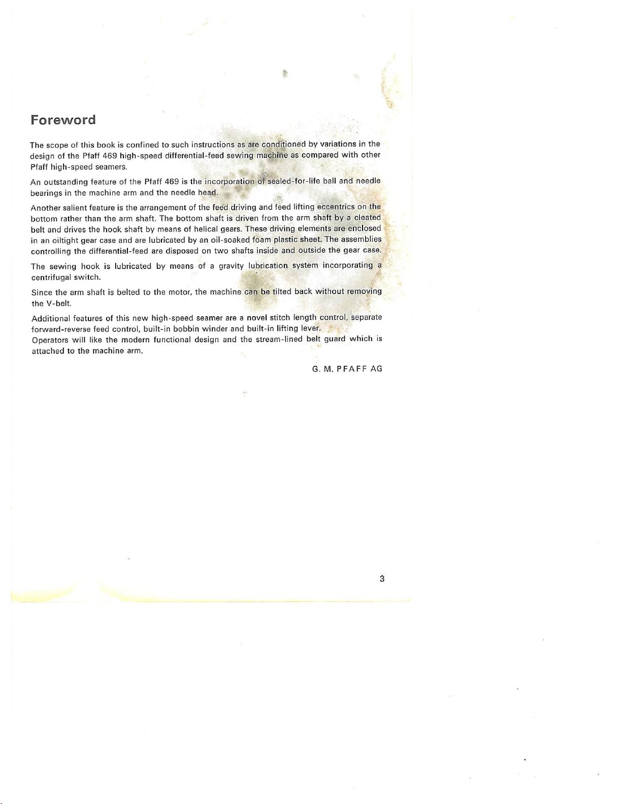
1.
Setting
Like all
feed
bracket
The front corners of
cushions
At
the
hinge
The
there
2.
Mounting
the
sewing
and
which
back,
brackets.
machine
Is will be
Up
the
other
modelsinthe
machine
cushion
are
the
new-type
This
is carefully
absorbed
the
Machine
can only be
set
the
bedplate are face-milled on
recessed
hinge
mounting
balanced
almost
V-Belt
The machine are shipped with
head
slightly
and
place
the
beltonthe
new
rangeofhigh-speed
set
up on a
power
the
into
the
tabletop.
studs
connect
prevents
the
and
completelybythe
the
belt guard removed. To mount
machine
the
machine
causes
practically no vibration.
rubber
and
seamers,
table
the
fitted with
Pfaff
the
469
new
underside and rest on matching
machine
from
motor
with
the
pinsinthe
comingincontact
hinge
brackets.
the
V-belt, lift
pulleys.
with
Whatever
differential-
rubber
hinge
rubber
two
rubber
the
tabletop.
vibration
the
sewing
Page 5
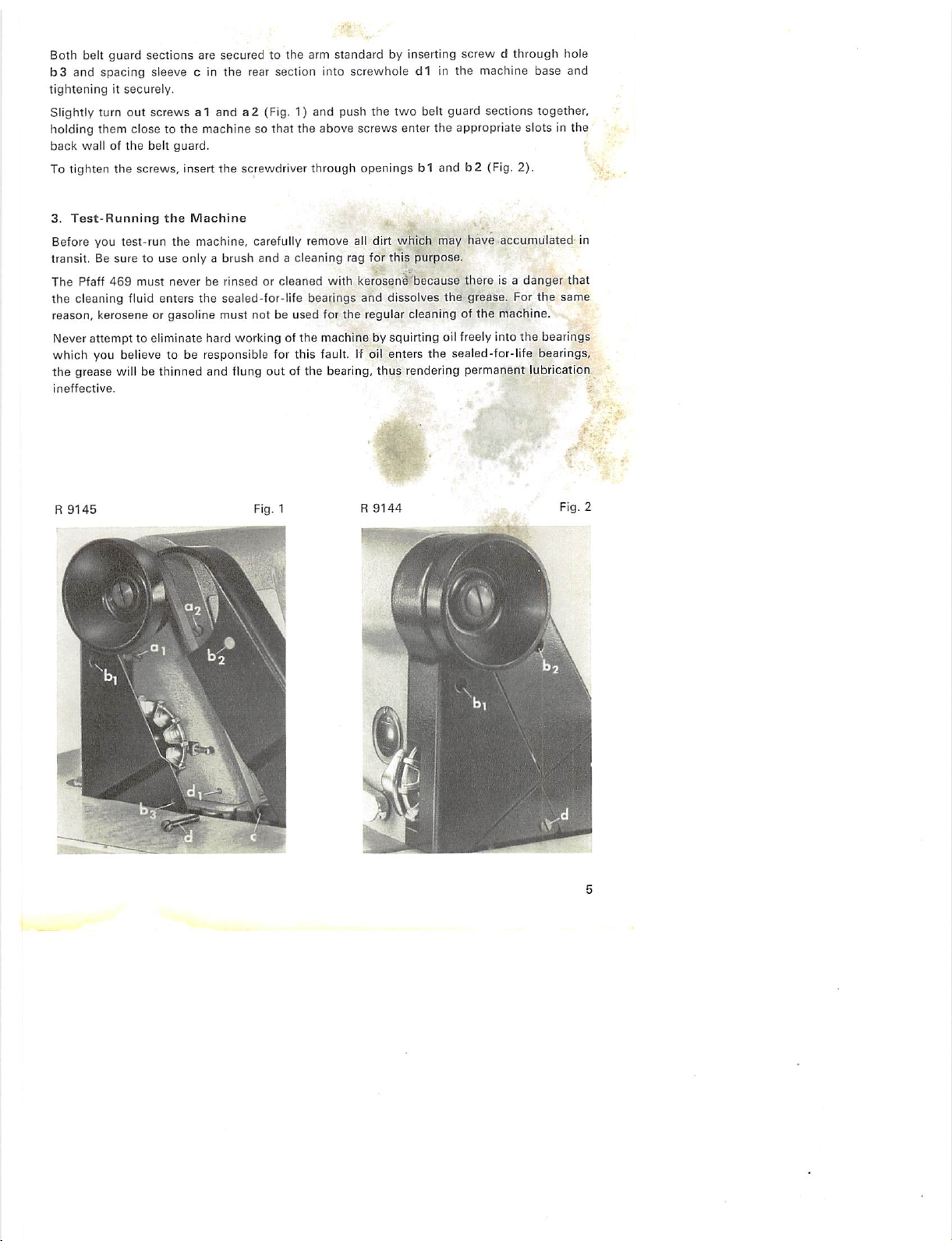
Both belt guard sections are secured to the arm standard by inserting screw d through hole
b3
and spacing sleeve c in the rear section into screwhole d1 in the machine base and
tighteningitsecurely.
Slightly turn
holding them
back
To tighten
3.
Test-Running
Before you test-run
transit. Be
The
Pfaff
out
wallofthe
the
suretouse
469
screws a1 anda2(Fig. 1) and push the
closetothe
belt
screws, insert
must
machine so
guard.
the
the
Machine
the
machine, carefully remove all dirt
onlyabrush
neverberinsedorcleaned
that
the
screwdriver through
andacleaning
above
with
two
screws
enter
openings
which
rag for
this
purpose.
kerosene'because
belt guard sections together,
the
appropriate slots in
b1 andb2(Fig. 2).
may
have
accumulated
there
is a
danger
the
that
the cleaning fluid enters the sealed-for-life bearings and dissolves the grease. For the same
reason, kerosene or gasoline must not be used for the regular cleaning of the machine.
Never
attempt
to eliminate hard working of
the
machine by squirting oil freely into
the
bearings
which you believe to be responsible for this fault. If oil enters the sealed-for-life bearings,
out
the grease will be thinned and flung
ineffective.
9145
R
of the bearing, thus rendering permanent lubrication
R
Fig. 1
9144
Fig.
in
;
2
Page 6
4.
Winding
the
Bobbin
The new high-speed seamer is fitted with a bobbin winder which is incorporated in the face
cover
rather
than
mounted
previously (Fig. 5).
operatortowind
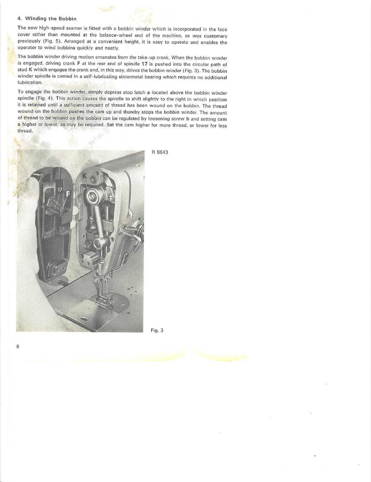
The bobbin winder driving motion emanates from the take-up crank. When the bobbin winder
is engaged,
stud K
driving
which
winder spindleis
lubrication.
To
engage
the
spindle
It is retained until a sufficient amount of thread has been wound on the bobbin. The thread
wound on the bobbin pushes the cam up and thereby stops the bobbin winder. The amount
(Fig.
ofthreadto be woundon the
a higher or lower, as may be required. Set the cam higher for more thread, or lower for less
thread.
Arranged
bobbins
crank F at the
engagesthe crankand, inthis
carried
bobbin winder, simply
4). Thisaction causes the
at the
balance-wheel
end
of the
machine,aswas
customary
at a convenient height, it is easy to operate and enables the
quickly
and
rear
neatly.
end of
way,
spindle
17 is pushed into the
drives
the
bobbin
winder
(Fig.
circular
3).The
path of
bobbin
in a self-lubricating sintermetal bearing which requires no additional
bobbin
depress
can be
stop
latch a located
spindle
to shift
regulatedbyloosening
slightly
R
above
the
to the
rightinwhich
screw b and settingcam
8643
bobbin
winder
position
4
Fig. 3
Page 7
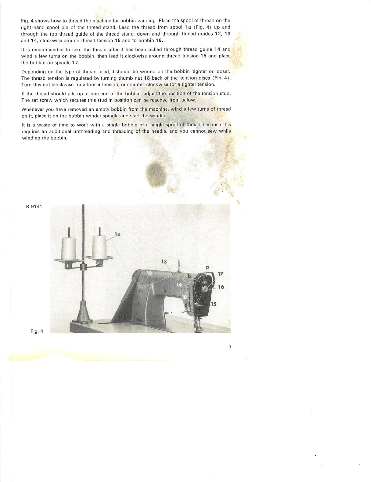
Fig, 4
shows
how
to thread
right-hand spool pin of
through
and
it is
windafew
the
Depending on
The
Turn
if
The
the top thread guide of the thread stand,
14,
clockwise
recommendedtotake
bobbinonspindle
thread
this
nut
the
thread
set
screw
around
turnsonthe
the
type of thread used, it
tensionisregulatedbyturning
clockwise
should
which
the
thread
bobbin,
17.
foralooser
pile up at
secures
the
machine for bobbin winding. Place
thread
stand.
Lead the thread from spool1a(Fig. 4) up and
tension15andtobobbin
the
thread
afterithas
then
leaditclockwise
shouldbewoundonthe
thumb
tension,orcounter-clockwise
one
endofthe
this
studinposition
bobbin,
Whenever you have removed an empty bobbin from
on it,
place
it on
the
bobbin
winder
spindle
and
start
It is a
wasteoftimetowork
withasingle
bobbin
requires an additional unthreading and threading of
winding
the
bobbin.
down
and
through
16.
been
pulled
through
around
thread
nut18backofthe
foratighter
adjust
the
positionofthe
canbereached
the
machine, wind a
the
winder.
or a
single
the
spoolofthread
needle,
from
and
the
spoolofthreadonthe
thread
guides
12,
thread
guide14and
tension15and
place
bobbin tighter or looser.
tension
discs
(Fig.
tension.
tension
stud.
below.
few
turns
of thread
because
you
cannot
sew
while
13
4).
this
R
9141
Fig. 4
Page 8
5.
Threading
the
Needle
Because of the high speed of this machine, it is particularly importantthat the thread passes
to
the
needle
smoothly.
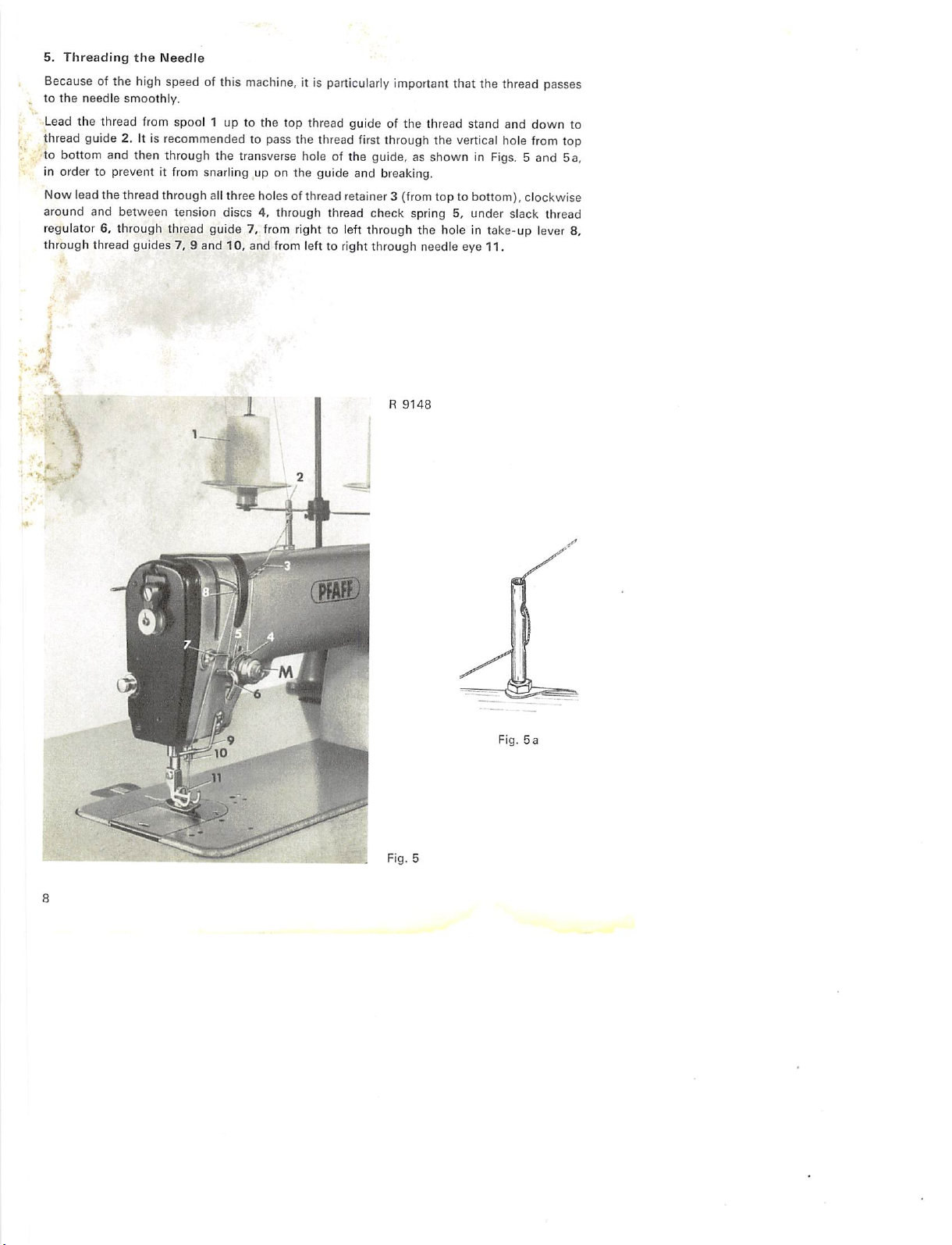
Lead
the
thread from spool 1 up to the top thread guide of
thread guide 2. it is recommended to pass the thread first through the
to bottom and then through the transverse hole of the guide, as shown in Figs. 5 and
the
thread
stand
vertical
and
hole
down
from
top
5a,
in order to prevent it from snarling up on the guide and breaking.
Now lead the thread through all three holes of thread retainer 3 (from top to bottom), clockwise
around and between tension discs 4, through thread check spring 5, under slack thread
regulator 6, through thread guide 7. from right to left through the hole In take-up lever 8.
through
thread
guides
7, 9
and
10,
and from left to right
through
R
9148
needle eye
11.
to
Fig.
5a
m
Fig. 5
Page 9

6.
Regulating
Two
separate
The
large
regulation.
by Vss". or
of
the
stitch
In
ordertoavoid
controlStis
pushed
Finger-tip control T serves to reverse
When
lever T is
set.
When
the
machine
If
desired,
backward
the
Stitch
controls
diameterofstitch
When
this
controlisturnedbyone
0.5
mm.
The
length
controlinmillimeters
that
securedinposition
back
slightly
when
pressed
lever
T is
released,
will
resume
the
machine
sewing.
Length
servetoregulate
length
controlStmakes
stitch
lengths
the
stitch
length
by a locking lever
setting
the
down,
the
machine
the
directionoffeedisinstantly
forward
can
stitching.
be fitted with a
the
lengthofstitch
tooth,
from 0 to 5/2
(Fig.
6).
setting
will be
stitch
length.
the
direction of feed
will
sew
second
and
reverse
the
direction
for an
exceedingly
the
stitch
lengthisincreasedordecreased
stitches
per
inch
disturbed
markedSpin Fig. 6. This lever
in reverse, making
treadle
while
andisoperated
reversedbyspring
for
switching
fine
stitch
are marked on
sewing,
for backtacking.
stitchesofthe
from
stitch
action
forward
of feed.
length
the
teeth
length
must
length
•
••
be
and
to
;
7. Regulating the Pressure on the Material ?
A
powerful
The
insertingascrewdriver
screw
flat
springinthe
machine
arm
exerts
the
necessary
amountofpressureisregulatedbyturningasmall
in for
more
pressure,orout
through
hole19on
for
less
the
pressure.
rightofthe
set
screw
-
pressure
which
spool
onthe
sewing
canbereachecf'by,
pin
(Fig.
6a).
fqiSt.
Tur^
r - ^
the
;
Fig. 6
R
9386
R
Fig.
6a
9147
Page 10

8.
Lifting
Since
lifting
To
The
has
pushed
(see
Motion
and a
lock
foot after it has been raised by knee action.
To
facilitate
knee
spring-loaded pin V (Fig. 7). As a
with
A new feature of this knee lever is a hinged knee platefitted with a foam plastic pad which is
contouredtohug
the
the
mechanism
mount
arm
the
Presser
standard
knee
Bar
has
been
couldbe enclosedinthe
lever,
pushitover
leverisheldinplacebyangular
entered
cutouts
t in
right-angled
onto
the
end
ofthe
shaft,
Fig.
7).
istransmitted
bellcrank
the
presser
lever
rock
a jerk.
tilting
from
lever
which
foot
inits
the
sewing
shaftis no
the
operator's
the
vertical
raises
highest
longer
head
screwed
knee.
set
closer
to the
machine
the
lower
bracketswhich
coupling
resilient
position.
bracketsmustbecompressedtoopenitslightly
shaftto the
the
presser
This
back
without
to the
result,
the knee lever can be
rear
edgeofthe
armso that it isnot
endofvertical
snaps
sleeveq(Fig.
presser
footby
foot.Asmall
leverisflicked
removing
angular
sleeve,
bedplate,
visible
shaftrunder
into
place
after
7).
When
the
coupling
means
ofa
crank,
hand
leverC(Fig.9)serves
to the
lefttoretain
the
knee
lever
but
rather
heldinplace
pulled
forward
the
presser
onthe outside.
the
tabletop.
transverse
pin
sleeve
aconnection
the
presser
completely,
off its shaft
bar
the
bya
u
is
to
R
9158
Fig. 7
10
Page 11

9.
Lubrication
Recent
advancesinthe
permanent
system.
Thankstothe
an oiltight
installed, a
speed
With
bearings,
The
to
the
is
opened
whenitstops,
The
lubricationofthis
basesothat
feature
sewing
all
essential
there
oil
reservoirofthe
sewing
by centrifugal
oil level in
incorporationofsealed-for-life
which
machine.
points
is no
needtoprovideagravity
hook
throughaplastic
thus
preventing
the
reservoirofthe
sight glass. If it is below
spout
of an ordinary oil
sewing
requirements.
hook,inaddition,
Turn
this
designofneedle
machine
various
opens
of friction
hook
lubrication
switch
the
mark on
can
into
bearings
without
feed
mechanisms
up a practically unlimited field of
having
systemislocatedinthe
tube.
The
F on
the
hook
any
oil
leakage
hook
lubrication
the
oil
the
small
hole
canberegulatedbyscrew
screw
in for less oil, or
have
madeitpossibletoensureasatisfactory
the
incorporation
bearings,
been
lubrication
oil
shaft
sight
above
the
machine
and
special
fitted
with
saaled-for-life
system,
except
machine
flowiscontrolledbyshut-off
when
the
machineisrunning,
(Fig.
10).
system
canbeinspected
glass, top up
the
oil
the
sight
w (Fig. 8)tosuit
out
for
more
oil.
of an
automatic
does
not
havetohave
attachments
canbeeasily
applicationstothis
ball
for
the
sewing
arm
and
valveVwhich
through
reservoir by inserting
glass.
The
flow
different
lubrication
high
and
needle
hook.
supplies
and
closed
the
of oil to
operational
y.
oil
oil
the
the
R
8603
Fig. 8
11
Page 12

The
correct
setting
for
normal
Remove
the
machine
spray
oil
operation
needle
plate
and
feed
dog
for about ten seconds at top speed. The setting is
appearonthe
paper.
can be
determined
and
placeasheetofpaper
by a
over
simple
the
opening.
correct
if two thin lines of
test,asfollows:
Then
run
In contrast to the sealed-for-life ball and needle bearings in the needle head which must
n|ver be
oiled,
take-up
lever
link
z is
lubricated
bya
wick
whichisenclosed
inan
oil
tubeand
is soaked with oil from the hook oil reservoir (Fig. 9).
To oil the needle bar bearings, put a few drops of oil into the foam-plastic-lined oil dents x
and y on the upper and lower needle bar bushings (Fig. 9). This should be done rather fre
quently during the first few weeks of operation. Occasionally, also apply some oil to the
presser
bar.
R
8900
Fig. 9
Pressureonthe
bv fiat
foot
has
action,
by
lever
12
spring
been
it Is
retainedinthis
C.
materialisexerted
B. After
the
raised
by
presser
knee
position
Page 13

The
feed
driving
and
feed
the
gear
case
are
lubricatedbytwo
regulating
mechanisms
oil-soaked
foam
as well as
plastic
the
sheets
hook
(pad
shaft
driving
lubrication).
gears
in
Oil has to be changed only once a year. To do this, tilt the machine back and unscrew the ' > ,
gear
case
cover.
If
the
foam plastic
to
remove
In
most
instances,
ones
which
must be well
same
thatisusedinthe
the
may be
metal
soaked
sheets
are to be re-used, they should first be
grit
which
has
accumulatedonthem.
however,
ordered
with
hook
it will be
by Nos.
sewing
lubrication
bettertoreplace
91-069
machine oil
system.
299-05
(2.7'E/50''C),
the
old
and
91-069302-05.
washed
foam
Order No.
in gasoline in
plastic
sheetsbynew
These
280-1-120110,
new
'
order,'
sheets
the
To soak both sheets thoroughly requires about 4 fl. oz., or 130 cu. cm., of oil.
When replacing the foam plastic sheets, make sure they fit properly
and
the
large
spur
gear
runs freely in the cutout of the large sheet. As you replace the gear case cover, check to see
that the gasket is not defective and make sure you tighten all screws evenly in order to prevent
oil
from
seeping
The oscillating feed rock shaft is grease-lubricated.
at
the
left
out.
endofthe
shaft
(Fig.
10).
Qrea^
is replenished through nipple N
'
.-'m
Note
When
filling
oil tube
the hookoil
leading
to shut-off
reservoirortopping
valveV(Fig.
Itup,take care that no air bubbles
10) because this would
interrupt
remain
the flow of
inthe
If an air bubble should nevertheless have formed ahead of shut-off valve V, pull the oil tube
offthe shut-off valve
nipple,
holditsend upso that the airbubble risesto the surface.Cautiously
replace the oil tube on the nipple, making sure no air is trapped in It.
An air bubble which may have formed In the short section of the oiltube is immaterial because
it can escape through oil flow regulating valve w (Fig. 10).
oil.
13
Page 14

R
8767
Fig.
10
The gear case cover and foam-plastic sheet P are
the machine. Bottom drive shaft A carries both feed driving eccentrics
removed.
To absorb dripping oil, place a collucotton pad under
SI
and S2 and hook shaft driving gear T
in the gear case, and feed lifting eccentrics H1 and H2 as well as bobbin case opener eccentric K near its left end.
The hook shaft carries centrifugal switch F whose stud pushes the valve stem to the right when the machine is in
operation, thereby opening hook lubrication shut-off valve V. When in its inoperative position, the valve stem
should be positioned
is
notinoperation.
'/i'".
or 1.5 mm. from the stud. The valve prevents the oil fromseeping out when the machine
The stitch length setting of the front feed dog is transmitted to shaft L, the left crank mechanism in the gear case,
the
inner
feed rock
shaft,
and
the
left
adjustable
The stroke of the back feed dog Is varied by means of two large thumb screws, a and b, on shaft
crank
which,
in turn,
transmits
it to
the
left feed bar.
IVI
and lever c
which connects with the treadle chain. This lever varies the stroke of the right feed bar by means of the right crank
mechanisminthe
14
gear
case.
Page 15

R
8412
Fig. 11
The
clearance
dogs are at the beginning or endtdf t^eir strokes Instretching and gathering, respectiveiy. •
10.
between both feed dogs is
Differential
Feed
smallest
when the
differential
feed is disengaged or when both feed
In order to produce durable seams or preventseam puckering, the sewing industry frequently
employs machines fitted with differential feed which can be set to gather or stretch the fabric
while
sewing.
To this end, the Pfaff 469 is equipped with two feed dogs arranged in tandem. For ordinary
sewing, both feed dogs are set so that their length oftravelis the same. Ifthey are set to move
differentially,
the
machine
gathersorstretches,
The Pfaff 469 is set for ordinary sewing, gathering or stretching by turning the two large
thumb
screwsaandbbelow
the
bedplate
(Fig.
10).
11.
Setting
the
Machine
for
Ordinary
Sewing
Toset both feed dogs so that their length of travel is the same, turn in thumb screws a and b
as faras they
will
go. Set thestitch
length
control
on"0" and checkto see that crankc,
which
connects with the treadle pitman, is in its horizontal position. To double-check this setting,
watch
the
feed motion
Ifadjustment is
required,
and
check
whether both feed
dogs
turn both thumb screws in or out, as
rise and fall exactly perpendicularly.
mayberequired.
The machine can now be set for any desired stitch length without disturbing the relative
positionsofthe
12.
Setting
To
produceagathering
the
feed
Machine
dogs.
effect,
for
the
Gathering
stroke
ofthe
front
feed
dog
mustbelonger
thanthe
stroke
ofthe rearfeed dog. This is accomplished byturning out thumb screw a (Fig.10).
Thedifferential feed motionis controlled by a smalltreadle.The harderthis treadle is depressed,
the
longer
the
stroke
ofthe
front
feed
dog
will
be and the
more
the
fabric
willbegathered.
15
Page 16

For
gathering,
is
dependent
Igngth
desired can be easily determined by a few test runs.
Each
thumb
Thjs
spring
vibration.Inaddition,
tbe screw in or out for adjustment.
Whenthe smalltreadle is released, both feed dogs again move
the
machine
Ifthe
machine
thumbscrew b
treadle
13.
Setting
To convert the Pfaff:469 frofn.'gathering to stretching, or vice versa, requires no exchanging
pr interchanging of fee(;| dbgs„^ -
•^eginbyturning
in unison and their Ipngth of travel corresponds to the stitch length set.
For stretching,
dogsothat
with the stitch length set. The amount of stretching is regulated by turning thumb screw b out,
as appropriate. To establish the correct relationship between both feeding motions requires
but
little
the
stitches
on the
increases.
How
screw
secures
ceasesgathering and
is to be
(Fig.
depressed
thd
all
Machine
thumb
the
stroke of the front feed dog must be shorter than
the
former retains
practice.
must
notbeset
stitch
length
set,
far
thumb
screwahastobe
hastwo
the
flat
spotsonits
screwinposition
this
spring
makesiteasiertocound
used
for
continuous
10) as faras it
the
time.
for
Stretching
resumes
sci^wainasfarasit
the
material slightly while
will
too
long
I.e.
the
amountofgathering
threaded
and
preventsitfrom
ordinary
gathering,
go.This
eliminates
willgoso
because
turned
stud
sewing,
its
the
the
strokeofthe
decreases
out
for
the
which
are
turning
as a
the
numberofturns
forward
making
stitchesof the lengthset.
setting
can be
the
necessityofkeeping
that
both
feed
the
stroke of
latter
advances
front
feed
dog
as the
stitch
amountofgathering
engagedbya
resultofmachine
in unison. As a result,
fixedbyturning
dogs
it in
when
turning
the
move
forward
the
rear feed
accordance
spring.
small
in
Fig.
R
8411
Theclearance between both feed dogs is largestwhen both feed dogs are at the
in gathering and stretching, respectively.
16
12
beginning
or end of theirstrokes
Page 17

Fig.
13
Tv^'
R
8770
A
f -.
:vy
-
.-^'.
When setting the machine for stretching, care must be taken that thumb screw b is not turned
out
beyond
Setting the machine for a longer stitch
The maximum
forward stroke and turning
stroke.
When
the
point at which
amount
the machine is set for stretching, depressing the small treadle will decrease
the
front feed dog begins to feed in reverse.
will
automatically increasethe amount of stretchih||.
of stretching will be obtained by setting the rear feed dog for its longest
out
thumb
nut b to
set
the
front feed dog for its maximum backward
the
amount
of stretching and switch the machine to ordinary sewing. The operator can thus reduce the
amountofstretching,asdesired,
or eliminate
stretching
altogether.
6.-
k f:
14.
Setting
the
Machine
for
Alternate
Gathering
and
Stretching
Afterturning thumb screws a and b out as far as they will go, practised operators will be able
to
stretch
and
gather
the
fabric alternately
Ifyou start sewing with this setting and without actuating the
while
sewing.
small
treadle,
the
fabric
will
be stretched more or less, depending on the stitch length set. The more you depress the
treadle,
the
more
the
amount
ordinary sewing and then to gathering. The
the
treadleispressed
of stretching will be reduced until the machine
down
as far as it will go.
maximum
amount of gathering is obtained when
changes
over to
Changing over from gathering to stretching and vice versa by simply pressing the treadle down
more or less requires a great deal of skill on the part of the operator. Most operators will
therefore prefer to set the desired amount of gathering or stretching by turning the regulating
screwsInor
out,asmayberequired.
17
Page 18

Ascale and a pointerare providedon the armstandard as a
feed.
Pointer
Z indicates the amount of gathering or stretching on the scale. Thegraduations
visual
aid in setting the differential
from 0 to + indicate the amount of gathering, while the graduations between 0 and — indicate
the amount of stretching. The graduation marks on the scale enable the operator to restore
any desired setting without having to sew a trial seam first (Fig. 13).
15.
Varieties
To suit different operational requirements, the Pfaff 469 can be easily converted into the
following varieties by exchanging its organizational parts.
Model
•A
•A
•A
B
B
C
C
(1.0)
(1.4)
(1.8)
(2.0)
Needle
Hole
Dia.
in
mm
1.0
1.2
1.4
1.6
1.8
2.0
2.2
*) If desired, fitted
**) Primarily
•*•)
dm=mean
16.
The
A trimming
position
The
vertical trimmer is
whether
The
knife driving
motion
bracket
holder
Thanks
intended
diameter.
Pfaff
469-431
machine
among
the
the
machineisset
mechanismisarrangedatthe
emanates
via a
bracket
to its
fromaneccentric
connection,anoscillating
movesupand
favorable
mechanismiscapable
The
trimmerisengaged
reachofthe
its
rear
a
locking
in
the
end,
latch
engaging
operator
via a link,
which
shaft
Max.
Stitch
Length,
'
Machine
Speed
in
in s.p'.m.
-:-5q00 .
7^'"
514
514
514
514
with
for
organized
subclassesofthe
arrangedtothe
kinematical
of paring
and
rotates
keeps
flange.
:5606
-
5000
4800
4800
4300
4300
Needle
System
stretching.
with
for
ordinary
down
design
the
edgeofthe
and
disengagedbyoperating
protrudes
the
knife
the
knife
r.p.m.
^Dia•*
in
11.8-•
118
118
112
112
100
100
mm
133.
differential feed,
Pfaff
469.
right of
the
sewing,
gatheringorstretching.
backofthe
on
the
arm
shaft
frame,acrank
on a
post.
and
its
fabric
from
under
the
engaging
engaging
lever
Motor
Pulley
Order
16-4371^0-55
16-437.120-55
16-437120-55
16-437110-55
16-437110-55
16-437090-55
16-437090-55
the
Pfaff
needle
and
andistransmitted
andaball-joint
pad
and
reservoir
while
the
a lever
machine
shaft.Acam
engagedineither
Needle Needle
Size
No.
469-431
in
100-110
occupiesaprominent
producesaclean
machine
arm.
to
connection.
lubrication,
machine
operatesattop
whichisarranged
arm.
When
this
securedonthis
oneoftwo
V100
90-100
The
the
lever is
System
mm
60
134
70
134
80
134
134
134
120 134
140
134
cut,
regardless
knife driving
knife
holder
The
the
trimming
speed.
within
actuated,
shaft
operates
notches
knife
easy
Page 19

The
trimming
margin,
i.e.
the
distance
from
the
trimmed
edge
to the
lineofstitching,ispre
determined and can only be changed by replacing the needle plate insert.
Setting the knife higher or lower is accomplished by shortening or lengthening the drive
connection. The setting is correct ifthe upper end of the cutting edge is
about
Vaa",or 1.0 mm,
below the cutting edge of the stationary knife when the top knife is at the lowest point of
its
stroke.
Attachedtothe
knife
holderbymeansofa
shim
prevfeusly,
the
knifeisnow
securedInplace
by adjustable jaws, but must still be pushed up as far as it will go.
The
knife
holder
canbeadjusted
The only time
exchangedtoobtain
Todothis,
the
lowest
adjust
the
the
engage
point
latter so
of its
knife holder has to be adjusted is after
a different trimming margin.
the
trimming
stroke.
that
the
lengthyvise
mechanism
Loosen
knife
and
and
the
two
contacts'the
crosswise.
rotate
the
balance
set
screwsonthe
stationary knife on
the
needle plate insert has been
wheel
until
the
frontofthe
knife
the
needle plate insert.
knife
holder
is at
and
Tighten both screws securely. Makesure the knife is set,correctiy lengthwise. Its lengthwise
setting is correct if it is centered in
right-hand
After
Needle
(2.5-7.0
-431/4
(8.0-12.0
side
of the knife holder and move
the
adjustment,
plate
inserts are
mm) in
stepsofabout
machines
canbesupplied
mm)instepsofabout
tighten
available
the
needle plate cutout. To
this
screw
for trimming
for
Upper
and
plate
insert)
Subclass-431/1
Subclass
-431
the
securely.
or
0.5
mm. On
trimming
or
1.0
mm.
lower
knives
are
availableinthe
/2
adjust,'loosen
the
screwonthe
knife forward or backward, as may be required.
margins
margins
Tool-steel
plate
Tool-steel
plate
special
(the
insert
insert
ranging
ranging
from
request,
from
latter
incorporatedinthe
following
top
knife
with
cutting
top
knife
and
about
Vaa" to
subclass
about
varieties:
and
tool-steel
edge
carbide-edged
-431/2
to
'/si"
and
'Vaa"
needle
needle
needle
Unless
specified
fitted with a
because
edge
trimming
being
both
even
the
otherwiseonthe
carbide-edged
the
when
margin of
most
customary.
top
knife
Subclass
Subclass
top
and
order,
knife
the
-431
-431/4
subclass
and
needle
/3
needle
plate
Carbide-edged
plate
insert
Carbide-edged
needle
-431
machines
plate
insert
put to hard use. In this case. Model A
Ve".or3.0
mm,
and
Model C
machines
top
knife
and
with
cutting
edge
top
knife
and
plate
insert
willbesuppliedinversion
insert. This version is
retainanexceptionally
and
B machines will be fitted for a
for
®/32",or4.0
mm,
tool-steel
carbide-edged
rated
very highly
keen
these
needle
/4
cutting
margins
19
Page 20

Fig.
14
fijpOOS
Fig..l,^,
R
8973
Employed
of
suited
Fig.
collars
for
16
for
and
the
the
simuliahgoLs
cuffs
previdti^io
stitchinji-„^'d
fining'Stitching
:ti^frt|^^er?ldoally^.^
productionof^{(c^i^lg^de,''e(c.
R
8999
previoH^.to
V..'
simultart^usfy.
Fig.
17
and
Irimrnmg
lurning
v-
the
over.
front
The
edgeofa
edge
tapeIsattached
sackcoal
R
9043
The knife actuating lever has a handy plate which
protrudes from under the machine arm. from the rear (cover removed).
20
Knife
drivingmechanism of the Pfaff469.431, as seen
Page 21

17.
Treadle
The Pfaff
the
differential
If
the
be called in to
Differential
feed
Operation
469
without thread trimmer is supplied with
feed
functions
adjust
control
and
reverse
the
performedbythe
the
differential
Forward
sewing
directionoffeedbyfoot
left
treadle
aretobe
feed
regulating
'•
•t..
•••*'.•
-v.
shaft
fc." •
two
treadles if it is desired to control 5,
action
(Fig.18).
reversed
(Fig.
18a),amechanic
crank. "
ReV6|ij|4^.Forward
couuiRS' sewing
A"
mi^
\
1
'
Fig.
18
1
}
/
Reserve
sewing
On Pfaff469-000 machines fitted with Stop,motor and automatic thread trimmer, the two ^V
treadles perform the functions illustrated in
i •
1
,-A. ' - i
''lO'
•'Li'ii.iii ti-'i
".C
•?.
V • '
'e
-1
f
"Figs.
19 and 19a. ;
*> V
•^Ifeire^ial
control
Differential
feed
control
Fig.
19
Raising
the
needle
trimming
the
threads
Whenthe tip of the
treadle is
depressed,
and
right
the
Forward
sewing
Lowering
the
treadle is
faster
needle
pressed
the
machine will sew.
Fig.
Raising
trimming
down, the
sewing
19a
the
the
machine
Reverse
needle
threads
sews
and
forward.
Forward
sewing
Lowering
the
needle
The
more
the
When the treadle is released again, the machinestops. When depressing the heel of the right
treadle,
the
needleislowered
for
turning
corners.
21
Page 22

Depressing
settingofthe
the
tipsofboth
differential
treadles
feed.
causes
the
machinetogatherorstretch,
depending
depressing the heel of the left treadle, the needle is-raisedand both threads are trimmed,
leaving ends of the proper length for starting the next seam.
The addition of new functions and the advantage afforded by combining
treadle
have
Pfaff
necesSit&ted a redistribution of
469-900/2
ma^nesiare so
designed
these
functionsonboth
that
sewing
and
thread
important phases of machine operation, are controlled by'the right treadle.
differential
thread
The
feed
trimmer, are
various
and
reversing
controlledbythe
possibilities
the
directir^offeed,
existing-t^e
likeonall
left treadle.
illustratedinFigs.20and
machines
20a.,,
all
functions in one
treadles.
trimming,
the
two
Varying
havingnoautomatic
onthe
most
the
Differential
feed
control
Fig.
20
r*-.'
Reverse
sewing
Reverse
Fig.
20a
;
:
sewing
F'orward^
1
1
.•
1
1
T T
\
- 1
•
. . Raising
"trimming
Forward
j
I
i
the
the
sewing
.
.MM
needle
threads
•—
Neutral
. \
:,V \
and
Neutral
• 'i'
.i-f b'ViT
\
•i-;,ne6dle
position
/
position
/
After
needle
After
needle
/•
sowing:
down
thread
up
sewing:
down
trimming;
^After
thread
trimming:
needle
up
Differential
feed
control
22
/
Raisng
the
needle
and
trimming
the
threads
Page 23

18.
If
desired,
Inching
every
Device
Pfaff
469
featuringanautomatic
needle
positioner
and
thread
trimmer
can,#
in addition, be fitted with an inching device which permits slow stitch-by-stitch sewing.'
This device is attached to the Stop motor and controlled by depressing the right treadle,'
When
the
tip of
the
right
treadleisdepressed
continuetopress
down
the tip of the
reached. Ifyou want to sew at top speed right away,
farasit
When
on
is
After
When
take-up
The
will
go.Inthis
you
havetoturnacornerorsewanintricatd^Section
the
treadle
until
If
you
allow
the
lowered
press
machines,orthe
needletobe
All
trimming
19.
Machines
equipped
initiating
for
On
pressure exerted subsequently, which moves
also
even
When
automatically,Tobring
down
the
sewing
has
raisedtoIts
the
treadleisreturned
lever
remains
work
can
nowbeeasily
machines
Raising
repositioning
these
raises
fitted
without
the
fitted
with a knee lever for raising not only
the
thread trimming action. This feature makes it possible to raise
machines,
the
after
the
pressure on
you operate
way,
the
inching
the
inching
device
becomes
treadletoreturn
heel of
the
been
completed,
heelofthe
right
left
highest
to its
to its
the
treadle.
press
treadle
point
neutral
at its highest point and the needle19positioned outside the
renrtoved
with
automatic
being
slowed
Needle
with
automatic
the
work.
a light
needletoits
the
treadle to resume
without
pressure
the
down
needle
highest
knee lever
thread
Thread
against
point.
lightly,
treadle,
device
operative
neutral
position,
needle
of a
The
work
down
on
subcl.
and
both
position
and
new
trimmer
first.
Trimming
positioner
the
the
A locking lever
and
the
sewing,
the
inching
deviceisenergized.
thp.sevyi.pp,
will
subcl.
can
the
threadst6f^e
.speed
mcr^ii^
quickly
depress of the treadle as
norbecome'b{3eralii^-'
ofthe
seam,
relieve
and
the
the
needleofsubcl.
-900
thenbeturned
heel
of the-'right
-900
machines.
after
the
machine
machine
trimrnedtothe
threadat-itsve
sews
to its
and
sewingberesumed.
treadleonsubcl.
This
workbeln$ertedv,^.j.,,"
canbeswitched
and
thread
the
presser foot,
knee
plate
raises
knee lever
treadle has been relieved.
the
through
retains
locking lever is released,
from
trimmer
but
the
presser
the
the
full
can,inaddition,
also
last third of its travel,
needleatthis
until
top speed is
the
stitchbystitch.
-900/2
machines
lowest
action
causes
proper
been
trimmed,
speedtothread
the
needle
the
presser foot
foot
andastronger
As you '
pressure
position,
-900/2
the
length.
the
material.
be
without
position
23
Page 24

Contents
Foreword
1. SettingUpthe Machine^', .
2. Mounting the V-Belt _ .
3.
Test-Running
Winding
4.
Threading
5.
6.
Regulating
7.
Regulating
8. Lifting
9.
Lubrication-.,.
10.
Differential
11.
Setting
12. Setting the Mactfne for Gathering .
13.
Setting
14.
Setting
15.
Varieties
16.
The
Pfaff
17.
Treadle
18.
Inching
19.
Raising
the
Machine
the
Bobbin
. ' . ' .
the
Needle
the
Stitch
Length
the
Pressureonthe
the
Presser
Bar
^^,
. s . •
Fe^;
-i,
the
Macl^e^fer
the
Macl^e'foj'.Stretching
the
Machine
.
...
469-431
Operation
Device
the
Needle
Ordinary
fdr
Alternate
. <
.
without
>
Material
Sewing.,5
Gathering
Thread
Trimming
and
,
.
Stretching
- .
3
4
4
5
6
8
9
9
10
11
15
15
15
16
17
18
18
21
23
23
24
 Loading...