

Page 1
PFAFF
(PFAFF
467
Instruction
and
Service
Book
Manual
R
9213
Page 2
(PHEE)
467
High-Speed
Sewing
with
Variable
Drop
Lockstitch
Machine
Feed
Top
Feed
Instruction
and
Service
Equipped
and
Book
Manual
G
M*PFAFFAG
KAISERSLAUTERN
BRANCH
Page 3
Foreword
This
instruction
sewing
questions
function
her
Since
creepofthe
operationofthe
A
positioner
The
time-wasting
freetomanipulate
so
The
by all
in
alike.
machine.
and
machine
the
special
incorporation
soon.
instructions
who
the
Pfaff
relatedtosewing
operationofthe
and
Pfaff
467isequipped
toporbottom
Service
and
thread
motions
service
467
book
contains
Though
not
exhaustively,itoffers
various
attain
maximum
ply in
top
feed
control
Manualisavailable
trimmer
of an
and,
the
for
mechanics
our
machinesinthe
make
greater
automatic
thus,
work
(Order
and
demands
much
valuable
intended
as a
information
full-scale
textbook
sufficient
mechanismstoenable
efficiencyasquicklyaspossible.
with
variable
stitching
shouldbestudied
affords
can
containedinthe
top
feed
"problem"
for
Pfaff
machines
No.
12310).
needle
positioner
notable
advantages.
achieveamuch
field
because
on
the
mechanical
very
second
the
which
materials,
carefully.
467-900
and
higher
partofthis
additional
skillsofassemblers
about
the
Pfaff
capableofanswering
informationonthe
every
operatortogettoknow
canbeset
thread
The
the
chapters
fitted
trimmer
operator
so as to
with
has
automatic
eliminates
outputofwork
book
willbewelcomed
mechanisms
467
high-speed
construction,
eliminate
dealing
both
without
incorporated
and
with
needle
many
her
hands
tiring
adjusters
all
any
the
G.M.PFAFF
AG
Page 4
R
9372
A.
Operating
1.
Brief
Description
Instructions
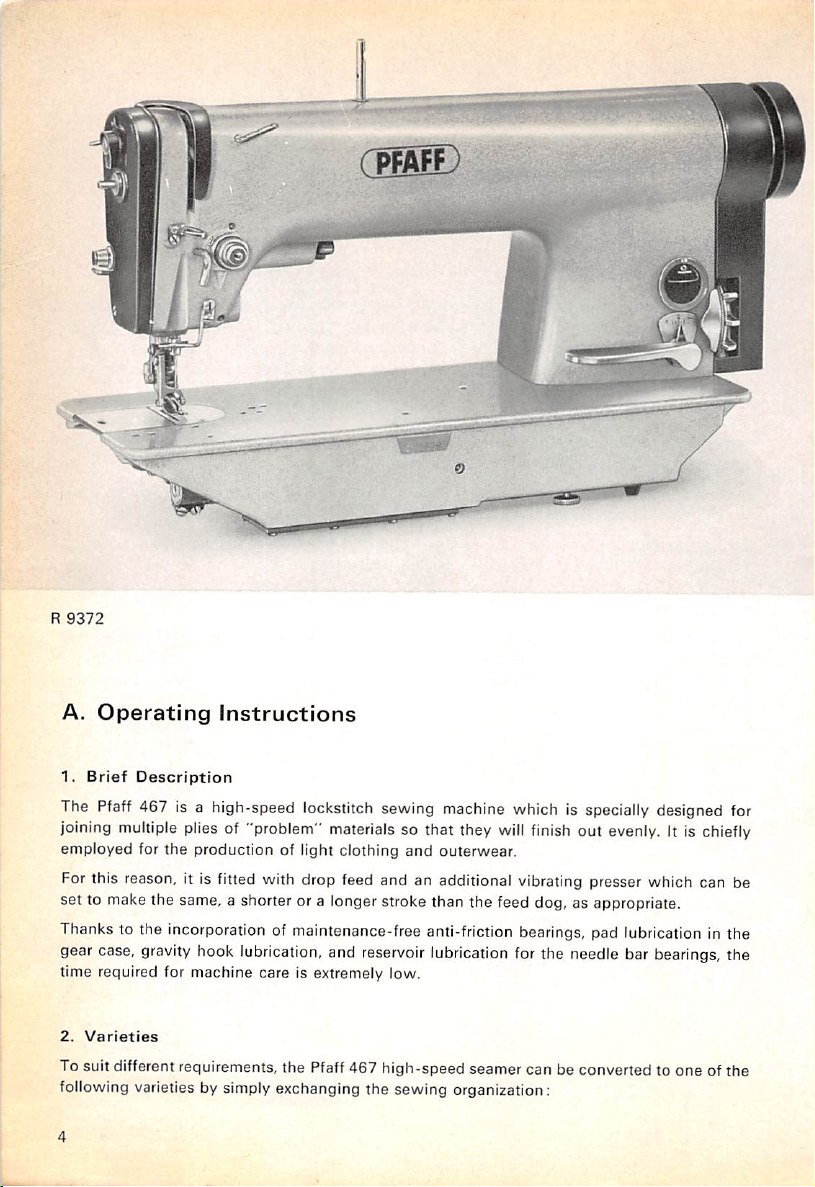
The Pfaff 467 is a high-speed lockstitch sewing machine which is specially designed for
finish
joining multiple plies of "problem" materials so that they will
employed for
the
production of light clothing
and
outerwear.
out evenly. It is chiefly
For this reason, it is fitted with drop feed and an additional vibrating presser which can be
set
to make the same, a shorter or a longer stroke than the feed dog, as appropriate.
Thanks to the incorporation of maintenance-freeanti-friction bearings, pad lubrication in the
gear case,
time required for machine care is extremely low.
2.
To suit different requirements, the Pfaff 467 high-speed seamer can be converted to one of the
following varieties by simply exchanging the sewing organization:
Varieties
gravity
hook lubrication, and reservoir lubrication for the needle bar bearings, the
Page 5
Model
A
A
A
B
B
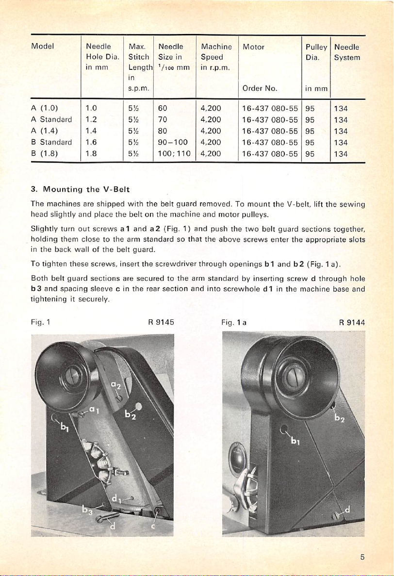
3.
(1.0)
Standard
(1.4)
Standard
(1.8)
Mounting
Needle
Hole
in
1.0
1.2
1.4
1.6
1.8
the
mm
Die.
V-Belt
Max.
Stitch
Length
in
s.p.m.
5)4
5)4
5)4
5)4
S'A
The machines are shipped with
head
slightly
and
place
the
beltonthe
Slightly
holding
In
To
Both
b3
tighteningItsecurely.
the
tighten
belt
and
turn
them
back
spacing
out
screwsa1anda2(Fig. 1)
closetothe
wallofthe
these
guard
screws,
sections
sleeve
arm
belt
insert
are
c In
guard.
the
Needle
Size
'/loo
60
70
80
90-100
100:110
the
belt guard removed. To mount
machine
standardsothat
the
screwdriver
securedtothe
rear
section
in
mm
Machine
Speed
In
r.p.m.
4,200
4,200
4,200
4,200
4,200
and
and
push
the
through
arm
standardbyInserting
and
Into
motor
the
above
Motor
Order
16-437
16-437
16-437
16-437
16-437
pulleys.
two
screws
No.
080-55
080-55
080-55
080-55
080-55
the
belt
enter
V-belt, lift
guard
the
Pulley
DIa.
In
95
95
95
95
95
sections
appropriate
openingsb1andb2(Fig. 1 a).
screwdthrough
screwhole
d1Inthe
machine
mm
Needle
System
134
134
134
134
134
the
sewing
together,
base
slots
hole
and
Fig. 1
R
9145
Fig. 1 a R
9144
Page 6
4.
Test-Running
Before
you
test-run
transit.Besuretouse
The
Pfaff
463
must
the
cleaning
reason,
Never
which
grease
ineffective.
Before
sameasthat
right
motor
fluid
enters
keroseneorgasoline
attempttoeliminate
you
believetobe
will be
thinned
you
connect
indicatedonthe
direction. If
terminal
the
box.
the
Machine
the
machine,
onlyabrush
neverberinsedorcleaned
the
hard
responsible
and
the
machinetothe
pulley
carefully
andacleaning
sealed-for-life
must
notbeused
workingofthe
for
flung
outofthe
rating
plateofthe
turnsinthe
this
electric
wrong
remove
bearings
fault. If oil
all dirt
rag for
this
with
kerosene
and
dissolves
for regular
machinebysquirting
bearings,
circuit,
motor,
cleaningofthe
enters
thus
checktosee
and
direction, merely
which
purpose.
because
the
sealed-for-life
rendering
that
the
exchange
may
there
the
oil
freely
permanent
that
motor
have
grease.
machine.
the
line
pulley
accimulated
is a
danger
For
the
into
the
bearings,
lubrication
voltageisthe
turnsinthe
two
wiresinthe
In
that
same
bearings
the
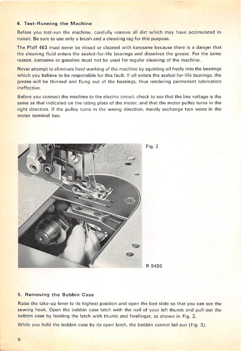
5.
Removing
Raise
sewing
bobbin
While
the
the
take-up
hook.
lever to its
Open
casebyholding
you
hold
the
Bobbin
the
bobbin
bobbin
the
case
Case
highest
latch
case
with
by its
position
latch
thumb
open
and
open
with
the
nail of
and
forefinger,asshown
latch,
the
. R
the
bobbin
9459
bed
slidesothat
your
cannot
left
thumb
in Fig. 2.
fall
out
you
and
(Fig.
can
pull
3).
see
out
the
the
Page 7
R
5868
R
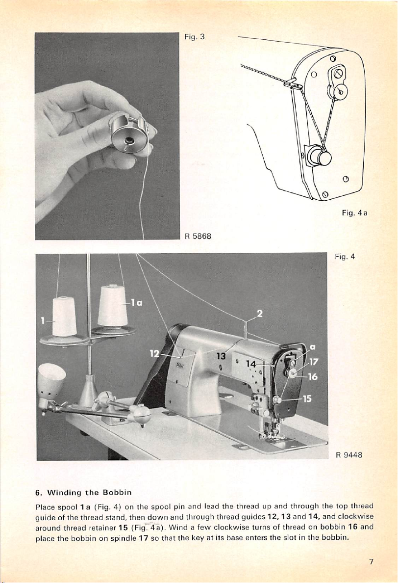
6.
Winding
Place spool 1 a (Fig. 4) on the
guide of the thread stand, then down and through thread guides
around thread retainer15(Fig'.
the
Bobbin
spool
pin and lead
4a).
Wind a few clockwise turns of thread on bobbin16and
the
thread up
and
through the top thread
12,13
and 14, and clockwise
place the bobbin on spindle 17 so that the key at its base enters the slot in the bobbin.
Fig.
9448
4a
Page 8
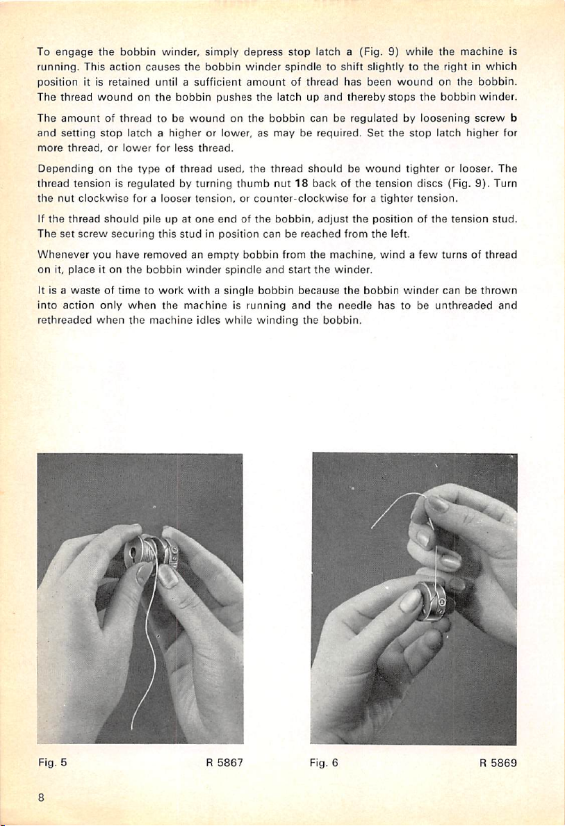
To
engage
running.
position
The
The
and
more
Dependingonthe
thread
the
If
the
The
Whenever
on
it,
It is a
into
rethreaded
the
bobbin
This
action
it is
retained
thread
woundonthe
amountofthreadtobe
setting
stop
latchahigherorlower,asmayberequired.
thread,orlower
typeofthread
tensionisregulatedbyturning
nut
clockwise
thread
set
screw
placeiton
you
for a
should
pileupat
securing
have
removedanempty
the
wasteoftimetowork
action
only
when
when
the
winder,
causes
the
until a
sufficient
bobbin
woundonthe
for
less
looser
tension,orcounter-clockwise
this
studinposition
bobbin
winder
withasingle
the
machineisrunning
machine
simply
bobbin
thread.
one
idles
depress
winder
amountofthread
pushes
the
used,
the
thumb
endofthe
canbereached
bobbin
spindle
and
bobbin
while
winding
stop
latch
a (Fig. 9)
spindletoshift
latchupand
bobbin
canberegulatedbyloosening
slightlytothe
has
been
thereby
Set
thread
shouldbewound
nut18backofthe
for a
bobbin,
from
start
and
adjust
the
the
because
the
the
bobbin.
the
from
machine,
winder.
the
needle
positionofthe
the
bobbin
while
wound
stops
the
stop
tighterorlooser.
tension
discs
tighter
tension.
left.
windafew
winder
hastobe
the
rightinwhich
on
the
the
bobbin
latch
(Fig.
tension
turnsofthread
canbethrown
unthreaded
machine
bobbin.
winder.
screw
higher
9).
is
b
for
The
Turn
stud.
and
Fig. 5
a
5867
R
Fig. 6
R
5869
Page 9
z
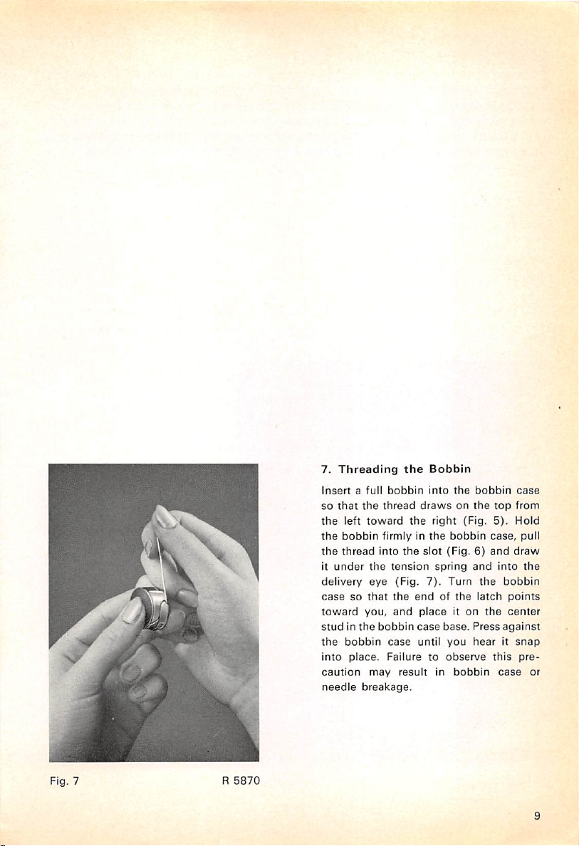
7.
Threading
Insertafull
so
that
the
the
left
toward
the
bobbin
the
thread
it
under
the
delivery
casesothat
toward
studinthe
the
into
caution
needle
eye
you,
bobbin
place.
may
breakage.
the
Bobbin
bobbin
Into
thread
drawsonthe
the
right
firmly in
into
bobbin
the
bobbin
the
slot
(Fig.6)and
tension
case
Failuretoobserve
(Fig.
the
and
result
spring
7).
Turn
endofthe
place
case
base.
until
you
in
the
bobbin
(Fig.
and
the
latch
it on
Press
hearitsnap
bobbin
case,
the
top
5).
into
bobbin
against
this
case
case
from
Hold
pull
draw
the
points
center
pre
or
Fig. 7 R
5870
Page 10
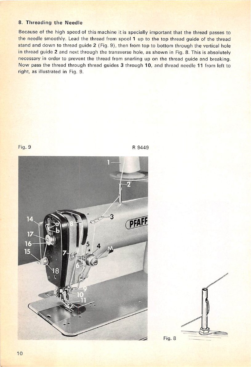
8.
Threading
Because of the high
the
needle smoothly. Lead
stand
and
in thread guide 2
necessary in order to prevent
Now
pass
right,
as
the
Needle
speed
down
to thread guide 2 (Fig. 9), then from top to bottom
and
next through
the
thread
through
illustrated in Fig. 9.
of this machine it is specially important
the
thread from spool 1 up to
the
transverse hole, as
the
thread from snarling up on
thread
guides3through
10.
the
shown
the
and
top thread
thread
that
the thread
guide
through
in Fig. 8. This is absolutely
thread
guide
needle
passes
of the thread
the
vertical hole
and breaking.
11 from left to
to
Fig. 9
/
U
R
9449
Fig. 8
10
Page 11
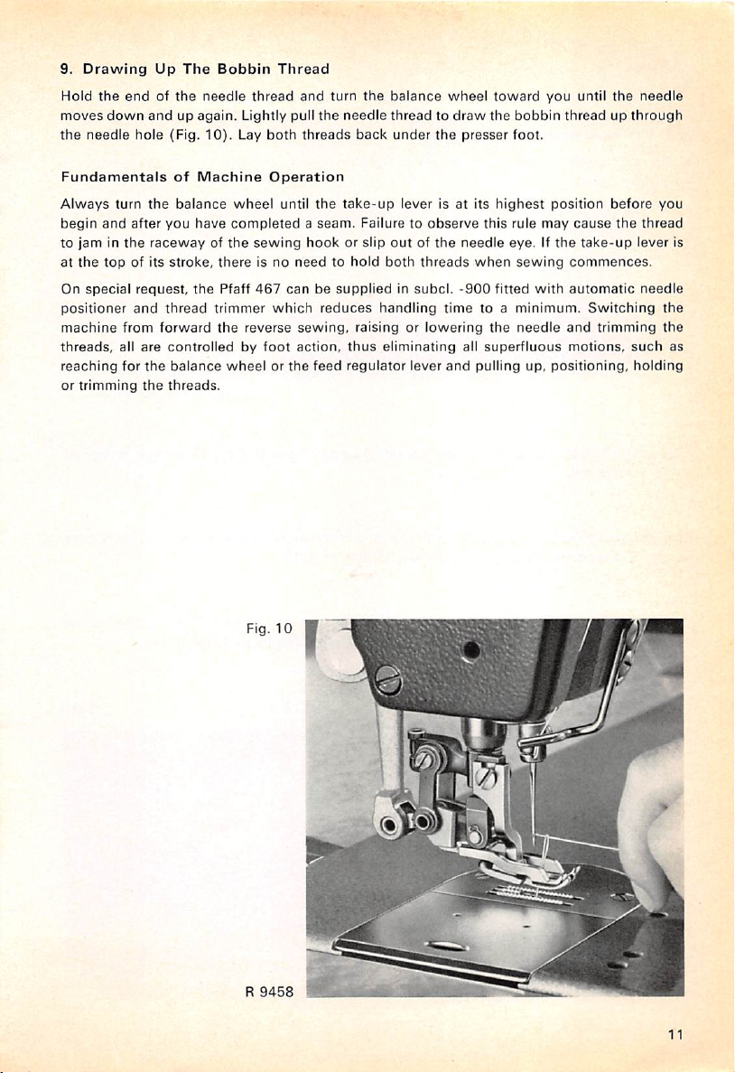
9.
Drawing
Hold
moves
the
the
down
needle
Up
endofthe
andupagain.
hole
(Fig.
The
Bobbin
needle
10).
thread
Lightly
Lay
Thread
both
and
pull
threads
the
turn
the
needle
back
balance
wheel
threadtodraw
under
the
presser
toward
the
foot.
you
bobbin
until
the
needle
threadupthrough
Fundamentals
Always
begin
to
at
On
turn
and
jaminthe
the
top
special
positioner
machine
threads,
reaching
or
all
for
trimming
of
the
balance
after
you
racewayofthe
of its
stroke,
request,
and
thread
from
forward
are
controlledbyfoot
the
balance
the
threads.
Machine
wheel
have
completedaseam.
sewing
thereisno
the
Pfaff
467
trimmer
the
reverse
wheelorthe
Fig.
Operation
until
the
take-up
lever
Failure to
hookorslip
needtohold
outofthe
both
canbesuppliedinsubcl.
which
reduces
sewing,
action,
feed
handling
raisingorlowering
thus
eliminating
regulator
10
observe
threads
lever
is at its
needle
-900
time
all
and
highest
this
rule
eye.Ifthe
when
sewing
fitted
to a
minimum.
the
needle
superfluous
pulling up,
position
may
cause
commences.
with
automatic
and
motions,
positioning,
before
the
take-up
Switching
trimming
you
thread
lever
needle
such
holding
is
the
the
as
R
9458
11
Page 12
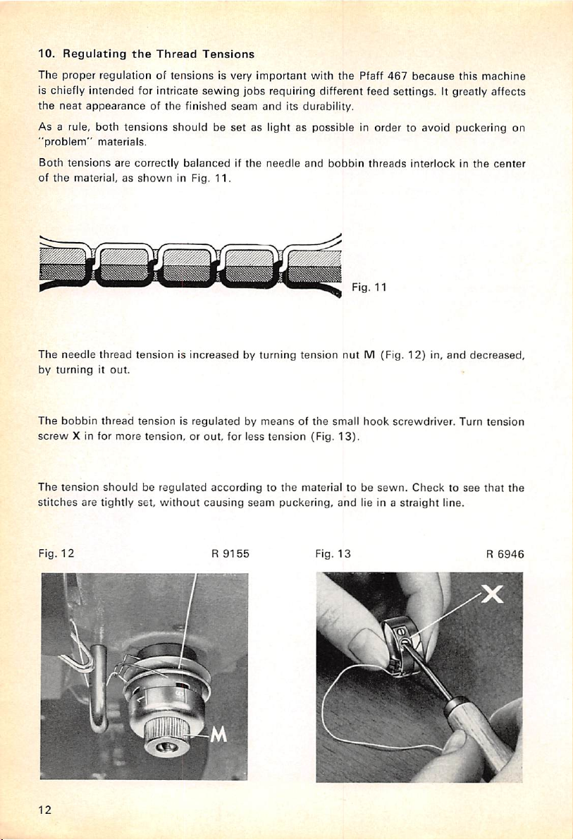
10.
The
Regulating
proper
the
Thread
regulationoftensions
Is chiefly intended for intricate
the
neat
appearanceofthe
As a rule, both
"problem"
Both
tensions
of
the
material, as
The
needle
by
turningitout.
The
bobbin
screw
X in for
tensions
materials.
are
thread
thread
more
shouldbeset
correctly
shown
in Fig.
tensionisincreasedbyturning
tensionisregulatedbymeansofthe
tension,orout,
Tensions
is very
sewing
jobs
finished
balancedifthe
seam
11.
for
less
Important
with
the
Pfaff
467
because
this
machine
requiring different feed settings. It greatly affects
and
its durability.
as light as possible in order to avoid puckering on
needle
and
bobbin
threads
tension
tension
(Fig.
nut
small
13).
Fig. 11
M (Fig.
hook
Interlockinthe
12)
in,
screwdriver.
and
decreased,
Turn
tension
center
The
tension
stitches
Fig.
12
12
shouldberegulated
are
tightly
set,
without
accordingtothe
causing
seam
R
9155
materialtobe
puckering,
Fig.
and
13
sewn.
lie in a
Checktosee
straight
line.
that
R
the
6946
Page 13
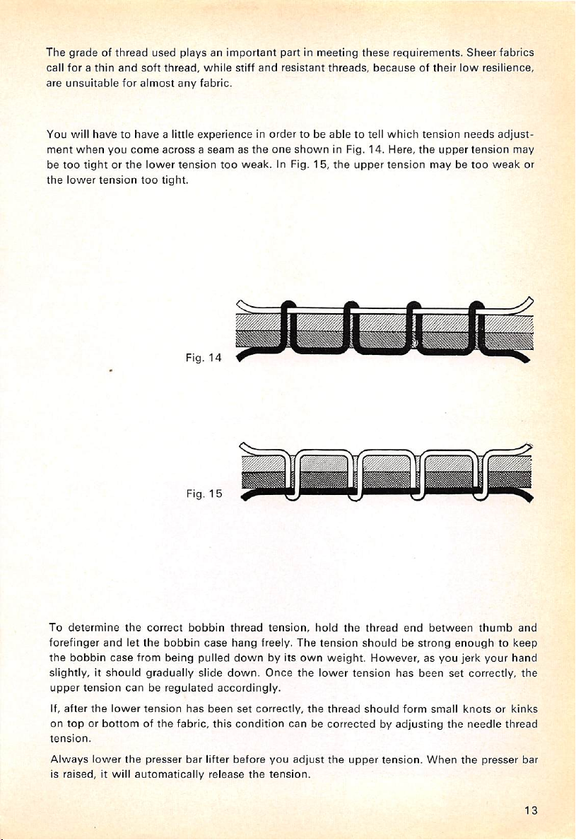
The
gradeofthread
call
forathin
are
unsuitable
You
will
ment
when
be
too
tightorthe
the
lower
and
soft
for
almost
havetohave
you
come
tension
too
used
playsanimportant
thread,
while
any
fabric.
a little
experienceinorder
acrossaseamasthe
lower
tension
too
tight.
Fig.
14
stiff
weak.
partinmeeting
and
resistant
to be
one
shown
In Fig.
15,
threads,
able
in Fig.
the
these
requirements.
becauseoftheir
to tell
which
14,
Here,
upper
tension
tension
the
upper
maybetoo
Sheer
low
needs
resilience,
tension
weak
fabrics
adjust
may
or
To
determine
forefinger
the
bobbin
and
the
let
case
slightly,itshould
upper
tension
If,
after
on
toporbottomofthe
tension.
Always
is
raised,
canberegulated
the
lower
lower
the
it will
Fig.
correct
the
bobbin
from
being
gradually
tension
has
fabric,
presser
bar
automatically
bobbin
case
pulled
slide
lifter
15
thread
hang
downbyits
down.
accordingly.
been
set
this
condition
before
release
tension,
freely.
Once
correctly,
The
own
the
hold
the
the
tension
weight.
lower
thread
canbecorrectedbyadjusting
you
adjust
the
upper
the
tension.
thread
end
shouldbestrong
However,asyou
tension
should
has
form
tension.
between
been
small
When
set
the
thumb
and
enoughtokeep
jerk
your
hand
correctly,
knotsorkinks
needle
the
thread
presser
the
bar
13
Page 14
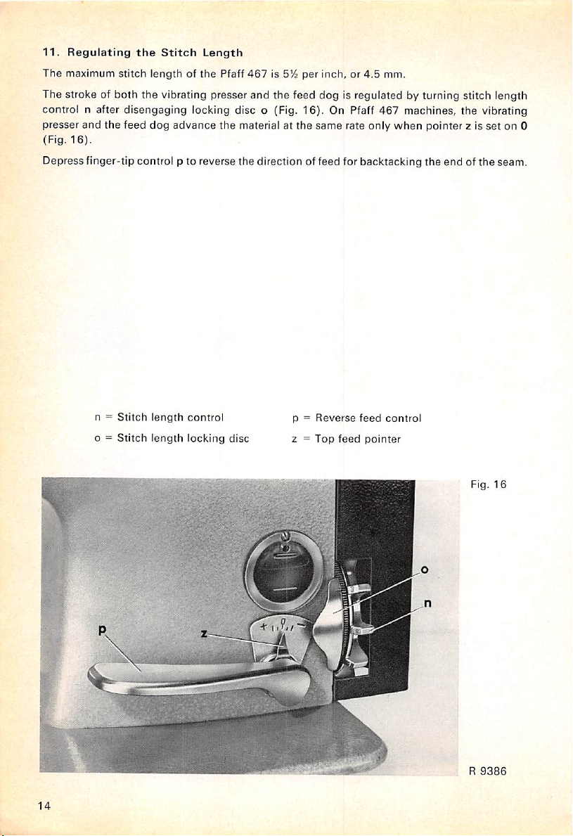
11.
The
Regulating
maximum
the
stitch
Stitch
Length
lengthofthe
Pfaff
467
is 5!^
per
inch, or
4.5
mm.
The stroke of both the vibrating presser and the feed dog is regulated by turning stitch length
control n after disengaging locking disc o (Fig. 16). On Pfaff 467 machines, the vibrating
presser
and
the
feed
dog
advance
(Fig.
16).
Depress finger-tip control p to reverse
n =
Stitch
length
o =
Stitch
length
control
locking
the
material at
the
disc
the
same
rate
direction of feed for backtacking the
p =
Reverse
2 =
Top
feed
only
feed
pointer
when
control
pointer
endofthe
z is
set
on 0
seam.
Fig.
16
R
9386
14
Page 15
12.
Varying
Dependingonthe
or
decreasedinrelationtothe
whichislocated
Before varying the stroke of the vibrating presser by hand,
out
as farasit will
it
hasaconvex
Turninscrew
As
screw
It
shouldbenoted,
reverse feed control p
the
feed
the
Top
typeofwork
under
go.
surface.
A to
A is
turned
dog,
whichisidentical
Feed
Stroke
being
strokeofthe
the
bedplate.
Screw
B is
the
increase
however,
the
strokeofthe
in,
pointerzswingstothe
that
screwAmust
begins
to swing
with
performed,
feed
For
easy
identification,
same
sizeasscrewA,but
vibrating
downward.
the
stitch
the
strokeofthe
dogbyturning
this
thumb
vibrating
thumb
screw
screw
differs from
presser,orturnitout,todecrease
left
(toward+)and
notbeturnedinbeyond
This is
the
point at
length,
beginstogrow
presserisIncreased
screwA(Fig.
hasaconcave
B should be
screw
the
top
ply is
the
pointatwhich
which
the
shorter.
17)
surface.
turned
A in
that
gathered.
stroke of
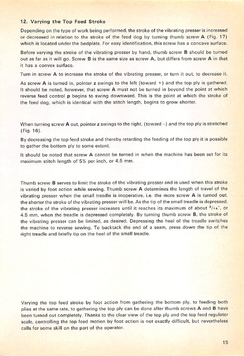
When turning screw A out, pointer z swings to the right, (toward-)and the top ply isstretched
(Fig.
16).
Bydecreasing the top feed stroke and thereby retarding the feeding of the top ply it is possible
to
gather
the
bottom
ply to
some
extent.
It
shouldbenoted
maximum
Thumb
stitch
screwBserves
that
screwAcannotbeturnedinwhen
length
of S'A per inch, or
to limit
the
strokeofthe
4.5
mm.
vibrating
the
presser
machine
andisused
has
been
when
set
this
for
stroke
is varied by foot action while sewing. Thumb screw A determines the length of travel of the
vibrating presser when the small treadle is inoperative, i.e. the more screw A is turned out,
the
shorter
the
stroke of
the
vibrating presser will be. As
the
tip of the small treadle is
depressed,
the stroke of the vibrating presser increases until it reaches its maximum of about Vi6", or
4.5 mm,
when
the
treadle is
depressed
completely. By turning
thumb
screwB,the
stroke of
the vibrating presser can be limited, as desired. Depressing the heel of the treadle switches
the machine to reverse
right treadle
and
sewing.
briefly tip on
To backtack the end of a seam, press
the
heel of
the
small treadle.
down
the
tip of the
it.
its
Varying
the
top feed stroke by foot action from gathering the
bottom
ply, to feeding both
plies at the same rate, to gathering the top ply can be done after thumb screws A and B have
been
turned
out
completely. Thanks to
the
clear view of
the
top ply
and
the
top feed regulator
scale, controlling the top feed motion by foot action is not exactly difficult, but nevertheless
calls
for
some
skill on
the
partofthe
operator.
15
Page 16
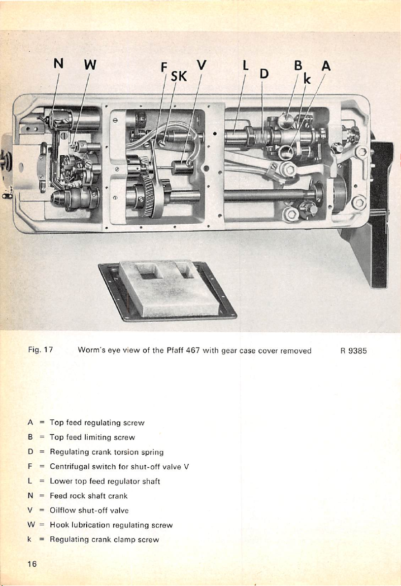
3
Fig. 17 Worm's eye view of
A =
Top
feed
B =
D =
F =
L =
N =
V =
W =
k =
16
Top
feed
Regulating
Centrifugal
Lower
top
Feed
rock
onflow
shut-off
Hook
lubrication
Regulating
regulating
limiting
crank
switch
feed
shaft
crank
screw
screw
torsion
for
regulator
crank
valve
regulating
clamp
shut-off
screw
the
spring
shaft
screw
Pfaff
valve
467
V
with
gear
case
cover removed R
9385
Page 17
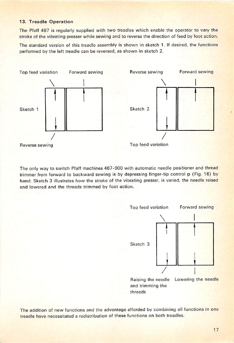
13.
Treadle
The Pfaff
strokeofthe
The
standard
Operation
467
vibrating
versionofthis
performedbythe
is regularly supplied with
presser
while
sewing
treadle
assemblyisshowninsketch
left
treadle
canbereversed,asshowninsketch
two
treadles which enable
andtoreverse
the
operator to vary the
the
directionoffeedbyfoot
1. If
desired,
2.
the
action.
functions
Top
feed
Sketch
Reverse
variation
1
sewing
Forward
sewing
The only way to switch Pfaff machines
467-900
Reverse
Sketch
Top
with automatic needle positioner and thread
feed
sewing
2
variation
Forward
trimmer from forward to backward sewing is by depressing finger-tip control p (Fig.
hand.
Sketch
and
lowered
3 illustrates
and
the
how
threads
the
strokeofthe
trimmedbyfoot
vibrating presser, is varied,
action.
Top
feed
variation
the
needle
Forward
\
sewing
16)
raised
sewing
by
The
additionofnew
treadle
have
functions
necessitatedaredistributionofthese
and
the
advantage
Sketch
3
Raising
the
needle
and
trimming
threads
the
affordedbycombining
functionsonboth
treadles.
Lowering
all
functionsinone
the
needle
17
Page 18
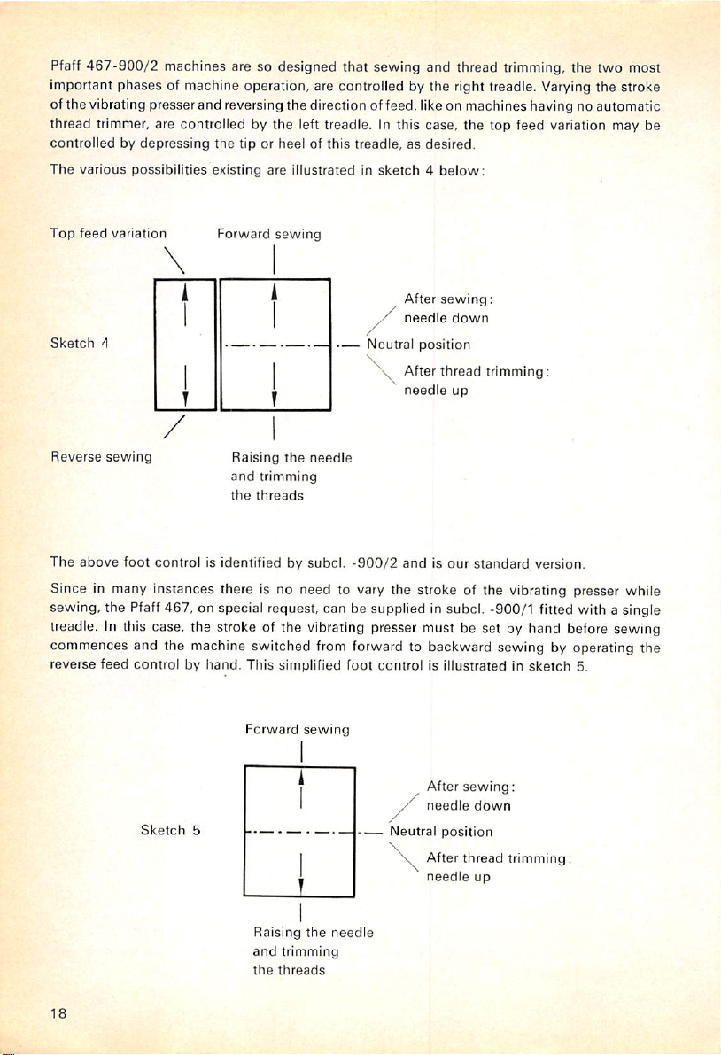
Pfaff
467-900/2
machines are so
designed
that
sewing
and
thread trimming, the
two
most
important phases of machine operation, are controlled by the right treadle. Varying the stroke
of
the
vibrating
thread trimmer, are controlled by
controlledbydepressing
The
various
Top
feed
Sketch
variation
4
presserand
possibilities
reversing
the
tip or
existing
Forward
the
direction of feed, like on machines having no automatic
the
left treadle. In this case, the top feed variation may be
heelofthis
are
illustratedinsketch4below;
sewing
treadle,asdesired.
After
needle
—
Neutral
position
Afterthread
needle
sewing:
down
trimming:
up
Reverse
The
above
sewing
and
foot
controlisidentifiedbysubcl.
Raising
trimming
the
threads
the
needle
-900/2
andisour
standard
version.
Since in many instances there is no need to vary the stroke of the vibrating presser while
sewing, the Pfaff 467, on special request, can be supplied in subcl. -900/1 fitted with a single
treadle. In this case, the stroke of the vibrating presser must be set by hand before sewing
commences and the machine switched from forward to backward sewing by operating the
reverse
feed
controlbyhand.
Sketch
This
simplified
Forward
5
Raising
and
trimming
the
threads
sewing
the
foot
controlisillustratedinsketch
After
needle
Neutral
position
After
needle
needle
sewing:
down
thread
up
5.
trimming:
18
Page 19

If
the
machine is fitted with an additional inching device, this device is
motor
and
controlledbydepressing
is
depressed
continuetopress
attained.Ifyou
downasfarasit will
When
on
the
becomes
If
you
machinesislowered
position,
be
resumed.
After
-900/2
the
needle
When
take-up
above
The
work
Machines
trimming
slightly,
the
down
wanttosewathigh
you
havetoturnacornerorsewanintricate
treadle until the inching device
operative
allow
press
sewing
machines,orthe
to be
the
treadleisreturnedtoits
lever
the
needle
can
fitted
without
and
the
treadletoreturntoits
automatically.Tobring
down
has
been
raised
remainsatits
plate.
nowbeeasily
with
slowing
inching
the
go.
the
the
heelofthe
completed,
heelofthe
to its
automatic
the
the
deviceisenergized
tip of
the
machine
sews
neutral
right
depress
left
highest
point
neutral
highest
point
removed
and
thread
machine
treadle
for
forward
treadle,
speed
the
right
the
pressure on
stitchbystitch.
position,
the
needle
treadle.
the
heelofthe
treadleonsubcl.
and
both
position
and
the
needleispositioned
new
workbeinserted.
trimmer
down
canbeswitched
first.
for
slow
sewing
away,
sectionofthe
the
of a
The
work
threads
after
attachedtothe
sewing.
quickly
the
needleofsubcl.
the
When
the
tip of
this
stitch-by-stitch
speed
increases
press
seam,
the
relieve
sewing.
until
top
tipofthe
the
treadle until the inching device
-900/1
and
subcl.
-900
can
thenbeturned
right
treadleonsubcl.
-900
machines.
to be
trimmedtothe
threads
machine
have
about
from full
to its
and
-900/1
This
action
proper
been
trimmed,
or
speedtothread
Stop
treadle
As you
speed
treadle
pressure
-900/2
lowest
sewing
and
causes
length.
8.0
mm,
is
the
Raising
Machines
equipped
Initiating
On
these
pressure
be
re-positioned.
the
Needle
fitted
with
withaknee
the
thread
machines,
exerted
subsequently
without
needle
lever
trimming
a light
positioner
which
action.
pressure
also
Thread
raises
against
raises
Trimming
and
not
only
the
the
automatic
the
knee
plate
needle
thread
presser
raises
to its
foot,
highest
trimmer
but
also
the
presser
pointsothat
can,inaddition,
the
needle,
without
foot
andastronger
the
work
be
can
19
Page 20

14.
Lifting
Both
The
presser
pushitover
angular
in
right-angled
When
compressedtoopenitslightly.
Motionistransmitted
andabellcrank
(Fig.
This
leverisflickedtothe
To facilitate
the
knee
byaspring-loaded
withaslight
A
new
touredtohug
the
the
vibrating
bar
the
bracketswhich
coupling
the
coupling
lever
20)
serves
the
lever
rock
jerk.
featureofthe
the
Presser
presser
lifting
lower
Bar
and
mechanismisenclosedInthe
endofvertical
snaps
sleeveq(Fig,
sleeveIspushed
from
the
which
raises
to lock
the
lefttoretain
tilting
backofthe
shaftisno
pin v
(Fig.
knee
lever
operator's
the
presser
Into
vertical
the
vibrating
sewing
longer
18)sothat
is its
knee.
foot
shaftrunder
place
after
18).
onto
the
shafttothe
presser
bar.Asmall
presser
the
presser
head
screwedtothe
the
hinged
are
mountedonthe
machine
the
transverse
endofthe
presser
and
the
bar
afterithas
without
angular
knee
lever
arm.Tomount
tabletop.
driving
shaft,
barbymeans
hand
leveratthe
presser
removing
sleeve,
canbepulled
foam-plastic-padded
presser
The
leverisheldinplace
pin u
has
resilient
foot
been
bracketsmust
of a
crank,aconnection
backofthe
in their
raisedbyknee
the
knee
but
rather
forward
knee
plate
bar.
the
entered
highest
lever
completely,
heldinplace
off
whichiscon
knee
cutouts
machine
position.
its
lever,
by
t
be
action.
shaft
Fig.
18
R
9158
20
Page 21

15.
Regulating
The
amountofpressure
the
Pressure
materialinordertoensure
of
the
fabric.
in
our
high-speed
spring
whichisincorporatedinthe
pressureonthe
The
pressureonthe
by
insertingashort
Turn
the
regulating
seamers,
presser
material is
screwdriver
screw
on
the
Material
to be
exertedbythe
smooth
feeding
the
conventional
machine
bar.
regulatedbyturningalong
in for
through
more
aperture19(Fig.
pressure,orout.
vibrating
presser
and
mustbeadaptedtothe
spiral
spring
has
been
arm
and
exertsaresilient
set
screw
19)
backofthe
for
less
pressure.
the
presser
thickness
replaced
and
which
footonthe
and
the
by a
long
easily
regulated
canbereached
spool
pin.
nature
flat
R
9147
21
Page 22

16.
Selecting
Pfaff
machines
diameter
Insert
the
sure
the
The
appearanceofthe
thread
and
the
Correct
467inModelsAandBuse
of ®/6a", or
needle
short
into
groove
2.0
mm.
the
openingofthe
faces
finished
fabric.
Lightweight
Needle
System
needle
toward
the
right.
seamisdependentonthe
fabrics
shouldbesewn
bar
134,
round-shank
and
push
correct relationship
with
ugly needle marks. When thick thread is used In a thin needle,
Thin thread used In a thick needle may
Select
the
proper
needle
and
thread
Needle
Size
Cotton
sizes
cause
skipped stitches.
from
the
Silk
chart
below:
needles
having a
it upasfarasit will
between
a thin
needleinordertoavoid
the
thread Is likely to break.
Synthetic
go.
shank
Make
needle,
70-80
80-90
90-100
100-110
110-120
Be
suretobuy
branded
100
80
70
50
35
needles
only. Never
use
100
80
60
50
40
rusty
120-100
90-80
70-60
50
40
needles.
Only superflnished needles ensure trouble-free sewing and prevent thread breakage. Rough-
surfaced needles tend to overheat quickly and burn the thread. This is particularly true of
synthetic threads which are very sensitive to heat and fuse easily.
For stitching synthetic threads, we recommend that you use superfinished, chromium-plated
needles
which
maybeobtained
from
us.
22
Page 23

17.
Machine
Although
hook
lubrication
maintenance,
To oil
the
plastic-lined
be
done
onceortwiceaweek,
each
week.
Care
the
Pfaff
system
several
needle
bar
dentsXand
Occasionally
467isequipped
and
pad
lubricationinthe
bearings
bearings,
y (Fig.
nevertheless
remove
20)onthe
depending
putafew
Fig.
20
with
the
drops
seaied-for-iife
gear
havetobe
face
cover
and
upper
and
on
how
many
of oil on
the
anti-friction
case
and,
carefully
putafew
lower
needle
hours
presser
bearings,anautomatic
thus,
requires
lubricatedbyhand.
drops
bar
the
machine
bar
felt
little
of oil into
bushings.
is in
washer.
additional
the
This
should
operation
foam-
R
9447
23
Page 24

Oilshould also be applied to the top feed drive joints and to the oiling points marked by arrows
in Fig.
40.
The oil level In the hook lubrication system can be inspected through the oil
is
below
the
mark, top up
at
the
top of
the
oil
quantity
If oil bubbles
adjusted,
of oil In
call
excess,orshort,ofthe
should
your
In order to ensure trouble-free sewing, form
and
removing
vicinityofthe
When
you
at the
needle-bar
oil
the
sewing
the
needle
endofthe
the
sight
glass. Make sure
reservoir by inserting the
the
oil level
proper
amount
spout
does
may
occur in the hook oilline or the oilflow to the
maintenance
lint
that
hook,
bar
man.
has
accumulated
usingabrush
bearings,
takeabrush
for
the
between
this
habit of tilting
feed dog and needle plate
purpose.
and
remove
machine. In this way, you prevent the particles of dressing which,
of the oil can into the aperture
not rise
above
cause
irregularities in
sewing
the
machine back
the
dust
which
sight
glass. If it
the
red mark. Any
the
hook has to be
onceaday
and
has
accumulated
oilflow.
in the
in most instances, contain plastic, from mixing with the oil and forming an undesirable film
on
the
parts.
The
machine
shouldbecleaned
with a dry, soft rag on
the
underside regularly.
24
Page 25

B.
Service
18.
The
When
mounting
the
motor
The
various
DIN
42691
a
hinge
bolt
be
requiredtotension
Although
to
withstand
we
urge
youtoadjust
too
loose
Thereisno
Instruction
V-Belt
the
pulley
becauseadistorted
motors
specifications.
and,
after
the
anti-friction
great
because
hard-and-fast
Drive
V-belt
usedtodrive
stress
both
tensioniscorrect,ifyou
pulleys.
Tighten
loose
of
the
the
hinge
while
sewing.Amotor
V-belt.
bolt
for
They
loosening
the
belt
bearings
and
eliminate
the
V-belt
conditions
rule
can
nutorthe
the
first
time,
care
belt
wears
the
Pfaff
467
are
pivotally
nut
correctly
Kl or a
connectedtothe
screw,
(Fig,
21).
incorporatedinthe
the
risk of
tensionsometiculously
may
cause
excessive
for
tensioning
compress
binding
that
hangsinthe
the
the
belt
screwonthe
shouldbetaken
out
rapidly.
are
standard
motors
canbeswungtoany
new
high-speed
excessive
V-belt,
about
V-belt
heatingorseizingofthe
that
the
wear.
butitmaybeassumed
% ofaninch
motor
bracketsothat
freely greatly
that
it is
not
forced
conformingtoGerman
motor
bracketbymeans
position
seamers
beltIsneither
are
too
that
midway
between
it will
reduces
the
that
designed
machine,
tight
the
not
service
onto
of
may
nor
belt
both
come
life
Fig.
R
21
9157
25
Page 26

19.
Timing
The
thread
occursasthe
ward
canbeadjustedbyturning
On
the
loosening
to time
you
must
The
thread
goods.
To
increaseordecrease
mechanism.
If
turning
and
take
of
the
the
Check
check
spring
lever
descends,
strokeofthe
new
set
the
be fully
the
out
thread
thread
high-speed
screwk(Fig,
thread
check
conversant
check
springiscorrectly
Turnitclockwisetoincrease
tension
stud
the
complete
check
spring
Spring
servestoassist
butisnot
check
the
regulator,asappropriate.
seamer,
34)onthe
spring
the
thread
the
take-up
yet
required
is limited by a
check
undersideofthe
spring correctly right away,
with
its
function.
timed
if it is
the
check
spring
tension,
the
tension,orcounter-clockwise,todecrease
withascrewdriver
tension
mechanism.
regulator.
Then
should
Slightly
readjust
lever in
for
spring
without
through
simply
prove
takingupthe
the
formationofthe
stoponthe
regulator
tension
trying
acting
turn
the
impossible,
loosen
the
strokeofthe
slack
stitch.
check
spring
canbeturned
barrel. In
out
different settings first,
when
the
needle
tension
studinthe
loosen
the
set
screwatthe
spring
thread
The
regulator
easily
ordertobe
reaches
screw
k (Fig.
meticulously.
which
down
tension
rear
and
after
able
the
it.
34)
end
26
Page 27

20.
Setting
The
needle
seam.
Correlating
referredtoas
If
the
exchanged,
the
needle
needle
needle
The
amountofneedle
the
Needle
and
hook
The
proper
timing of
the
needle
"adjusting
amountofneedle
beginbyroughly
bar
set
screw,
the
barsothat
plate
(Fig.
22).
BaratCorrect
motions
both
and
hook
the
needle
bar
rise
setting
move
its
bottom
rise
required
Height
mustbeproperly
motions
requires
synchronizedinordertoobtainaperfect
utmost
motionssoastoensure
rise".
mustbereset,
the
needle
the
needle
endisabout
to form
for
bar to
bar
connecting
Va",or13.0
the
loop
accuracy.
instance,
the
correct
on Pfaff
proper
loop
after
the
positionasfollows:
link to its
mm,
467
lowest
above
machines,
formation
needle
position,
the
top
i.e.
by which the needle has to rise from the lowest point of its stroke, normally is
or
1.8
mm.
To
set
this
amount
by us
(Order
Turn
the
balance
the
gauge
onto
No.
880137/00onthe
This
done,
pull
the
clamp
strikes
correctly, it is
No.
91-129
604-01).
wheel
until
the
needle bar, pushing it
needle
out
the
gauge
the
needle
recommended
the
needle
bar,
push
and
cautiously turn
bar
bushing.
bar
against
it up
Now
that
has
you use
reached
the
the
all-purpose
lowest
point
gauge
of its
the lower needle bar bushing. Place clamp
against
the
gauge
and
screwitdown
the
begin
balance
to time
wheel in
the
sewing
sewing
hook,
normally
bar
has
been
Loosen
and
set
surfaceofthe
the
distance
about
Vi6",
supplied
stroke.
Slip
(Fig.
23).
direction until
is
Fig. 22
R
9470
27
Page 28

21.
Timing
When
the
needle
Vaa",or0.8
If
adjustmentisrequired,
Then
the
turn
the
needle
thread
mm,
the
sewing
Sewing
has
passed
loop,
above
Hook
the
the
pointofthe
the
topofthe
remove
the
hookonits
Fig.
R
9537
lowest
point
of its
stroke
and
sewing
hook
shouldbeopposite
needle
eye.
needle
plate
and
loosen
hook
shaft,asmayberequiredtomeet
23
risen V<6", or
set
screws1and2(Fig.
the
1.8
its
above
center
mm, to form
line
and
24).
condition.
Fig.
24
R
9488
28
Page 29

At
the
same
time,
set
the
both
parts
When
hook,
(Fig. 25)
being
adjusting
take
care
which
.004",
the
lateral
that
the
serves to
hookasclosetothe
or 0.1
mm.
positionofthe
hubofthe
conduct
balancing
oil to
needleaspossible,
sewing
collar
the
sewing
hook,
does
hook
for
not
and
example,
bear
was
Emerging from oil flow regulating valve R (Fig. 24), the oil flows
oil retainer ring LR which is
borehole
in its
hub
from
which
capped
oil
drips
over
into
the
the
hook
shaft
oil
grooveinthe
bearing bushing and has a small
the
proper
against
introduced
through
balancing
clearance
after
oil
copper
inserting a
retainer
some
collar.
between
ring LR
time ago.
tube
new
1 into
Fig.
R
25
O
9169
29
Page 30

22.
Dismantling
Practised
when
when
If
as
thread,
1.
2.
3.
4.
5. Let
6.
operators
beginning or ending a
beginningtosew,
thread
should
you
turn
the
dismantle
Pull
out
Raise
needle
If not,
beginbyunscrewing
Loosen
binding
of
actionofthe
Seize
the
machine
the
sewing
Take
out
gib
d. Do
the
Sewing
who
have
will hardly
happentojaminthe
balance
the
bobbin
together
the
not
the
knee
bar
screw
head
three
confuse
wheel
sewing
lever
and
sewing
case
with
hook
and
take-up
e (Fig.
cap
the
down
hook
Hook
formed
the
habit
seam,
or of laying both
ever
encounter
racewayofthe
back
and
forth slightly. If
hook,asinstructed
tilt
the
machine
lever,
provided
bobbin
case
29)
and
swing
hook.
by its
latch
with
bobbin.
again
and
unscrew
gib
screws
el.
e2
gibdwith
thread
of raising
the
take-up
threads
thread
jamminginthe
sewing
below:
back.
the
position
opener
thumb
needle
ande3(Figs.26and
pull-off
hook,
this
action
balance
finger
bracket
fingerKforward
and
forefinger
plate
flangef(Fig.
lever
back under
however,
fails to
wheel
can
A (Fig.
and
and
feed
28)
28).
to its
highest
the
hook
try to pull it
free
still be
27).
outofthe
pull it
dog.
and
remove
sewing
raceway.
the
jammed
turned.
outofthe
point
foot
out
range
hook
Fig.
26
R
9486
30
Page 31

7.
Rotate
on
outofsewing
seen
of
the
thread
that
sewing
balance
pull-off
hookg.This
point
1 of
hookgand
Fig.
27
R
9162
wheel
until
sloti(Figs.27and28)
flangef.Wheninthis
position is
the
bobbin
case
flange
thread
pull-off
flange
is in line
position,
also
the
bobbin
illustrated in Fig.28from
mustbepositioned
f.
with
case
between
the
first
base
whichitmay
the
set
screw
canbetaken
two
points
f 1
be
Fig.
R
28
ei
e2
©3
d
5086
31
Page 32

8. Seize the bobbin case base by its center stud and tilt it out of the sewing hook, pulling
it
down
andtothe
left.
9. Thoroughly clean the hook raceway and the bobbin case flange and remove all lint with
a
pointed
wooden
10.
Before you replace the bobbin
instrument,
never
withascrewdriver.
case
base, it is best to
screw
on bobbin
case
position
finger bracket A.When replacing the bobbin case base, make sure finger h on bracket A
enters
slot
I in
the
rim of
the
bobbin
case
base.
Also
11.
checktosee
about
V64", or 0.5 mm, wide between the tip of position finger h and the bottom of slot i.
Replace
hook
gibdand
turninset
screws
el,
e2
and
e3.
that
there
is a
clearance
12. Swing the mechanical opener back to its original position and adjust as instructed in
Chapter 24. This tricky job
should
be performed by your
maintenance
man.
23.
The
Mechanical
Opener
Allmodels of the Pfaff 467 are regularly fitted with a positive mechanical opener. The doublerevolution rotary hook of the Pfaff 467 enters the needle thread loop at every other revolution
and
passesitaround
On
machines
slightly in
oder
the
stationary
havingnomechanical
to make an
opening
bobbin
opener,
through
case.
the
which
needle
thread
it can pass.
hastoturn
the
bobbin
case
The friction between hook raceway and bobbin case flange and the attendant pressure of the
position finger against the wall of the position slot increase in proportion to the sewing
speed
so that the needle thread has to overcome a stronger resistance when opening a clearance gap.
On machines fitted with mechanical opener, the opener finger slightly rotates the bobbin case
at
the
right
time
and
thread
can
pass
on
the
needle thread will remain
exposed
to additional stress, particularly at higher
contrarytothe
freely
between
directionofsewing
position
finger
the
same, regardless of
and
position
sewing
hook
slot.
the
sewing
speeds.
rotationsothat
This
ensures
speed
because
Since
the
danger
that
the
needle
the
tension
it is not
of thread
breaking has been largely eliminated, it is possible to use threads of a lower tensile strength
even
for
high-speed
sewing
operations.
Another advantage afforded by the mechanical opener is that even lightweight fabrics can be
sewn
at full
speed
while
the
machineisbeing
32
run in, or
afteranew
hook
has
been
inserted.
Page 33

24.
Timing
Accurate
so
that
you
tackle
advantage
There
1.
2.
On
the
lifting
over,
and
carries
opener
crank
case
opener
if the
rotates
slot
and
the
Mechanical
settingofthe
they
prefertorenderitinoperative
this
adjustment,
affordedbythis
are
two
different
The
adjustmentofthe
the
timingofthe
new
high-speed
shaftonthe
the
feed
shaft.
mechanism
opener
left of
lifting
the
feed
The
throwofthis
and
finger
canbeadjustedbyloosening
finger on its
opener
finger at its extreme left position
the
latter
counter-clockwise
ensure
that
shouldbe.012",or0.3
shaftistimed
(Fig. 29)
correctly. To
and
rotate the rear eccentric on
Opener
bobbin
case
opener
it is
imperative
device
are
discussedindetail.
adjustments
mechanical
seamers,
the
shaftofthe
lifting
eccentric
mechanical
sewing
required:
opener
the
feed
hook,asseen
Pfaff
and,
eccentricistransmittedtothe
the
bobbin
case
shaft,asappropriate.
just
the
needle
thread
mm,
wide
(Fig.
time
the
seemstopresentaproblemtomany
rather
opener
467
behind
thangoto
that
you revert to
drive,
finger.
rock
shaftisarrangedonthe
from
is of
the
it, an
the
and
the
rotating
eccentric
troubleofadjusting
Chapter23againinwhich
hook-endofthe
rather
which
eccentric
opener
shaft.
The
oscillating
The
mechanical
contacts
sufficiently to
can
pass
31).
Prerequisite for
mechanical
the
feed lifting shaft.
binding
through
screw
e (Fig.
openerisset
the
projection on the bobbin
center
the
position
the
clearance
thisisthat
opener,
loosen
both
right,
machine.
than
the
drives
the
connecting
motionofthe
29)
and
correctly
finger in
gap
freely.
the
mechanical
set
screwsaand
mechanics
it.
and
the
oscillating
bobbin
turning
on its
case
the
position
This
Before
the
feed
More
type
case
rod, a
bobbin
the
shaft
and
gap
opener
b
Fig.
R
29
'4
9163
33
Page 34

The bobbin case opener is timed correctly if the bobbin case opener eccentric is at its extreme
left position
when
the
needle bar has passed
the
lowest
point of its stroke
and
risen . or
1.8 mm. When the eccentric is at this position, the clearance gap between the opener finger
and
the
wallofthe
position
slotiswidest.
To make sure the mechanical opener has been timed correctly, check to see that the opener
finger
contacts
has cast off the loop and its point has reached a position
and
top
Since
the
positions,
motion of
the
projection on
i.e.atnortheast.
the
opener
the
bobbin
finger is very
case
slow
and
begins
to rotate it
about
midway between the right
and
hardly perceptible, we recommend
when
the hook
that you push the bobbin case over to the right at the bottom and place a thin piece of paper
between the finger and the projection on the bobbin case. When the finger begins to hold
the
paper
bobbin
case.
In adjusting
in place, it has reached
the
mechanical opener, care
the
position at which it will normally begin to rotate
should
be taken
that
there is a clearance of .03",
the
or 0.8 mm, between the opener finger and the face of the bobbin case (Fig. 30), and of .012",
or 0.3 mm,
between
the
opener
finger and
the
wall of the position slot (Fig.
31).
Fig.
30
25.
Dismantling
There are
In
the
first,
two
take-up
Fig. 31
the
procedures
link
Link
Take-up
that
may be followed;
Lis
left
inthe
machine
and is
disconnected
from
take-up
lever
F by
turning out screw z (Fig. 34). Swing the take-up lever up, and the link down, as shown in
Fig. 32. Pull the
34
take-up
lever
through
the
slot
and
out of
the
machine.
Page 35

Fig.
R
9161
Turn
the
balance
wheel
until
take-up
the machine arm rear cover (Fig.
needle bar is at its
machine.
Now
connecting
lowest
pull
the
link, forward
point, and let
take-up
outofthe
32
crank
33).
Loosen
the
crank,
together
needle bar crank.
set
screws3and4appearinthe
these
take-up
screws,
lever drop back
with
the
turn
take-up
the
balance
through
lever
aperture
underneath
wheel
the slot into the
and
the
until the
needle
bar
Fig.
R
33
9485
35
Page 36

The second possibility consists in dismantling the complete take-up leverassembly, including
the
take-up
To do this, pull the lower oil tube off the nipple of shut-off valve V (Fig. 42) and drain the oil
into a clean vessel. Unscrew the oil reservoir back of the oil sight glass and detach from the
reservoir the oil
To facilitate seizing the take-up link hinge stud, replace plug screw 1 (Fig. 34) by a M 4 set
screw. Loosen the three set screws that can be reached from above and pull the hinge stud,
together
To dismantle the
above, swing take-up link L down onto the take-up crank at its left position, and pull the
take-up
When
extends
link.
with
assembly
replacing
beyond
tube
conducting
the
oil
tube,
take-up
outofthe
the
oil
tube,
the oil holes in
oil to
the
take-up
forward
lever assembly, loosen
outofthe
needle
bar
checktosee
the
take-up
crank.
that
link hinge stud.
machine.
take-up
crank
the
wickinthe
link hinge stud.
set
screws3and
oil
tubeisnot
4, as instructed
torn
off
and
26.
Changing
the
Needle
Bar
To dismantle the needle bar, remove needle, needle plate, feed dog, bobbin case position
finger
bracket
and
link (Fig. 34)
sewing
and
hook.
Loosen
pull the needle bar
binding
down
and
screws
q and r in the
out
of the machine. In order to
needle
bar
connecting
save
the
time-consuming repetitionof timingthe sewing hook and the mechanicalopener, itis recom
mended to loosen set screws p (Fig. 34) and g (Fig. 23) of needle bar frame S, screw z
(Fig.
34) in the take-up
take-up
of the machine. The needle bar can now be easily exchanged.
link
Land
In replacingthe needle bar
hole exactly. Before you tighten set screws p and g securely, turn the balance wheel to make
surethe
any
Todothis,
Take
appropriate.
36
needleiscentered
play.Ifnecessary,
loosen
a screwdriver and turn the eccentric stud underneath this screw to the
link,
pull
the
adjust
eccentric
and take-up crank set screws 3 and 4
needle
bar
frame,
together
frame,
take care that the needle is centered sideways inthe needle
correctly
the
stud set
and the
position
screw
front-end
ofthe
g and
needle
turn
with
parts
inthe
out
the
needle
needle
take-up
work
bar
(Fig.
33). Swing away
lever
smoothly
holeinsewing
frame
topset
assembly,
without
having
direction.
screw
rightorleft,
out
as
p.
Page 37

27.
Dismantling
Flat
spring
end
restsona
The long pressure regulating
end
exerts resilient
can
be easily
The
Pfaff
467
ball
whichisembeddedingrease
The
upper
the
B (Fig.
stud
pressure
removed
has
two
endofthe
Presser
34)isabout
screwed
into
screw
on a
from
the
presser
jnner
presser
Bar
8",or20.0
the
depresses
steel
machine
bars,
one
and
bar
mm,
long
and
back
wailofthe
machine
flat spring B more or less so
ball at
the
topofthe
arm
after
turning
inside
the
other.
locatedatthe
carries
topofthe
a bracket,
The
while
slightly
and
presser
out
the
pressure
inner
the
bearing enclosing the vibrating presser fulcrum stud. The hollow
another
The
bottomofthe
bracket
at its
presser
footisattachedtothe
outer
top
presser
end
Fig.
bar.
and
the
vibrating
left-hand
34
presser
sideofthe
lever
assembly
mounting
bent.
Its
seml-clrcular
protrudingonthe
that
its long tapering
bar.
The
presser
pressure
presser
regulating
spring
engages
bar.
lower
end
outer
presser bar carries
carries
at its
bracket
locatedatthe
bar
the
bottom
rear
inside.
spring
screw.
steel
a roller
end.
R
9447
37
Page 38

28.
Conversion
To convert
tilt
the
machine
Relieve
the
(Fig.
19).
Before you install a new vibrating presser,
bracket
andonthe
to
Another
the
machine to
back
and
pressureofthe
vibrating
another
strip
presser
presser
Subclass
subclass, remove presser foot, needle plate and feed dog,
the
vibrating presser.
bar
springbyturning
checktosee
are
clean.
out
pressure
that
the mounting surfaces on
regulating
screw
the
Loosen binding screw K (Fig. 40) on the driving lever and check to make sure the vibrating
presser
The
should
sure
After all the parts replaced have
29.
works
smoothly.
guide
should
haveavertical
clearanceof.004",
or 0.1
be replaced by new ones. As you replace the feed dog
the
former
moves
Setting
the
freely in
Feed
the
feed
been
DogatCorrect
slots.
adjusted
Height
correctly, reset
mm,
maximum.
and
the
Worn
the
needle
presser foot pressure.
connections
plate, make
To facilitate this adjustment, it is recommended to use all-purpose gauge No. 91 -129 604-01
which is pushed over the feed slot so that its
plate. This
gauge
is held in place by the presser foot (Fig. 35). If
are in line with the
the
feed
edges
dog
of the needle
has
been
set
edges
correctly, all its teeth should contact the bottom of the recess on the underside of the gauge
when
the
feed
dog
Prerequisite
correctly, as
To
set
the
is at its
for
setting
instructedinChapter
feed
dogatthe
the
highest
feed
correct
point.
dogatthe
35.
height,
correct
heightisthat
proceedasfollows:
its
motion
has
been
timed
19
Fig.
35
R
9534
38
Page 39

Fig.
R
36
9526
Checktosee
feed
dogatthe
feed
lifting link
The front
which
screw
crank
as crank TS is slowly
that
feed
lifting
eccentric
correct
height,
loosen
HG,asappropriate.
Fig.
37
R
9159a
endofthe
hasaneccentric
feed dog is adjusted vertically by turning feed rock
left
end.Todo
9 on the right clamp crank K9
TS.
Turning feed rock
shaftSWnow
swung
from its foremost position
HE is at its
binding
this,
and
highest
screwGS(Fig.
remove
the
the
two binding
will present no difficulty
point. To
36)
gear
case
screwsuand
toward
set
the
and
adjust
shaft
cover
and
becauseitstarts
the
needle. The
v on feed driving
easily secured in position by pressing against its end. Then the crank can be
and
turning
the
shaft
canberepeated
until
the
feed
dogissetatthe
correct
rear
edgeofthe
the
SW
loosen
shaft
swung
height.
position
(Fig.
binding
revolving
can
of
37)
be
back,
39
Page 40

Push
the
shaft
toward
Set
the
machine
rock
shaft
Tighten
30.
When
will
When
a
shouldbecenteredinthe
binding
Adjusting
you
go,
then
the
clearanceofabout
for its
crankisnot
screwsuandvsecurely.
the
Presser
mount
the
presser
tighten
the
presser
bar is raised, i.e.
^/i6", or
1
the
right
longest
distorted
set
screw
needle
and
tighten
stitch,
turn
on its
Foot
footonthe
securely.
the
5.0
mm,
holeofthe
the
shaft
machine,
presser
between
presser
binding
and
screw
balance
the
feed
push
bar
lifter is flicked to
presser
foot.
9 on
clamp
wheel
and
checktosee
dogiscenteredinthe
it up
against
the
the
foot
and
needle
Fig.
38
crankK9securely.
that
the
feed
bracketasfarasit
left,
there
should
plate
and
the
needle
feed
slot.
be
R
9540
If adjustment is required, push all-purpose gauge No. 91
-129604-01,
which is 5.0 mm thick,
horizontally between presser foot and needle plate (Fig. 38). Then loosen grub screw G
(Fig. 40) on the driving lever connection and push the fulcrum stud out of its bearing. Next,
loosen binding screws a and b on the two presser bar brackets (Fig. 34).
Adjust the presser foot until the needle is centered correctly in its needle hole and tighten
binding screw b on the lower bracket securely. Replace the fulcrum stud in the driving lever
bearing, making sure that it enters the hole easily and the vibrating presser moves freely.
If there should be a bind, straighten the driving lever.
Tighten the screw on the upper presser bar bracket only after the vibrating presser has been
adjusted
As you tighten grub
40
properly.
screw
G, make sure it
engages
the
flat
spot
on the fulcrum stud.
Page 41

31.
Adjusting
Lower
the
wheel
until
at
its
extreme
positionisconcealedbythe
link V (Fig.
right
position
of its
1.8
bracket
against
As
youdothis,
The
inner
binding
rotate
slightlysothat
pressure
screwa.Then
pushing
After this
presser
the
rolleratthe
left,asseen
34)
when
mm
gauge
the
and
outer
screw
a on
against
check
it in
the
adjustment,
the
Vibrating
bar so
whichisvisible
the
roller isatits
blade
rollerat
note
the
presser
the
the
driving
the driving elements
whether
opposite
tighten
that
the
topofthe
from
presser
under
the
topof
following:
bars
slotted
elements
the
direction
binding
Presser
presser
small
the
needle-bar
bar
below
extreme
the
the
are
presser
vibrating
slightly.
foot
restsonthe
two-armed
endofthe
and
the
needle
the
lower
left.
vibrating
presser
two-armed
connected
bar
bracket
become
and
screw
wedged.Toavoid
the vibrating presser while tightening binding
presser
K on
needle
lever
behind
bar
connecting
presser
Push
the
all-purpose
(Fig.
lever,
and
by
various
tendstocause
moves
freely. If it
the
driving lever
plate.
Then
the
presser
machine.
bar
39),
Since
link,
bracket
gauge
press
tighten binding
driving
the
this, exert a
does
securely
turn
watch
andisat
the
upper
elements.
inner
not,
ther
balance
barispositioned
the
rollerinthis
connecting
its
extreme
with
the
prongs
presser
screw
a securely.
Tightening
presser
bar
slight
counter-
readjust
(Fig.
while
40).
bar
to
Fig.
R
39
f
9542
41
Page 42

32.
Correlating
To
ensure
smooth
to
the
feed
dog
tooth
rows.Avibrating
damage
Eccentric
positionofthe
and
settingisobtained.
The
its
After
turn
vibrating
feed
the
delicate
studEz(Fig.
eccentric
presser
stroke.
adjustment,
Top
and
Bottom
feeding,
with
great
the
care.
presser
fabrics.
40)atthe
vibrating
presserinrelationtothe
stud
Ez to
shouldbeadjustedsothatitengages
tighten
screwIsecurely.
Feeds
positionofthe
Thisisparticularly
that
engages
topofthe
the
rightorleft
vibrating
the
top
feed
with
presser
importantifboth
material
feed
drive
dog.Todo
the
aid
with
connecting
of a
the
material
Fig.
shouldbeadjustedinrelation
these
parts
have
long
oneortwo
this,
screwdriver
40
teeth
link
servestoadjust
loosen
until
consistently
only
alien
screw
the
throughout
may
the
correct
i
33.
Adjusting
On
subcl.-7and
so
that
its
needle
machines,sothat
42
the
similar
hole
the
Vibrating
machines,
is in line
vibrating
Presser
with
the
vibrating
thatinthe
in
Sewing
presser
needle
presseriscenteredinthe
R
9375
Direction
shouldbeadjustedinsewing
plate,
andonsubcl.
frame-type
-6/2
shoeofthe
presser
direction
and
similar
foot.
Page 43

34.
Zeroing
Set
stitch length control n on 0 (Fig,
that
the
sewing.
the
Top
vibrating presser
and
and
Bottom
Feeds
16).
Then rotate
the
feed dog make no perceptible motion in
the
balance
wheel and
checktosee
the
direction of
If the feed dog should make any lengthwise motion, eliminate this motion by turning the
upper
feed regulating shaft. To do this, seize hexagon nut SR (Fig. 41) at
of
the
shaft
(which
servestotension
torsion
spring
DU)
withaSW22wrench
the
right-hand
and
end
loosen
binding screw Km on the ball-end clamp crank. Adjust the upper feed regulating shaft with
a
wrench
while turning
the
balance
Fig. 41
wheel until
B
the
feed dog makes no motion at alt.
Then
tighten
Set
stitch
regulating
As
you
stitch
length
to
cause
would
disturb
motion.
binding
length
screw
make
this
controln.This
barBato
the
R
screw
control
n on
A until
barBacontacts
adjustment,
contact
settingofthe
9483
Kmonthe
4.5
make
means
the
upper
upper
and
sure
that
clamp
turn
the
the
regulating
feed
regulating
feed
crank.
out
regulating
upper
ball
screwAmustbeturnedinonly
regulating
screwBcompletely.
feed
regulating
end
remainsInengagementinthe
shaft
lightly.
Turning
shaft
which
shaft.
controls
screw
the
Then
far
A in
drop
turn
slot
enough
too
feed
in
of
far
43
Page 44

The
exact
lime
when
barBacontacts
control p
o and turn stitch length control n
should
any lengthwise motion
on
Todothis,
by inserting a
on its
feeds,
its
swing
shaft
shaft
the
because
down
at this time
instantly
when
(Fig.
43),asmayberequired.
remove
the
arm
screwdriver
and
tighten
the
position of
the
the
latter starts
back
without
stitch length control n is
standard
through
set
the
screw
securely again. If,as a result of zeroing
differential
scale in relation to the top feed pointer.
are
tensioned
correctly
and
retension,ifnecessary.
the
shaft
may be
descending.
to 0. When you
having
any
rear
cover
and
lower
oval
top
feed
scale
Check
whether
determinedbywatching
Loosen stitch length locking disc
depress
reverse feed control p now, it
play. If the vibrating presser
set
on 0, adjust by turning crank LK
loosen
the
set
screwonthe
aperture.
Adjust
the
positionofcrank
the
should
have
been
disturbed,
torsion springs DO
Fig.
41 a
and
reverse
should
clamp
top
and
bottom
center
DU (Fig. 41)
feed
make
crank
LK
the
35.
Timing
When
the
meticulously
to
readjust
while
repairing
To
check
to
the
maximum
lowest
point
91-129
604-00
44
the
Bottom
machineisassembledatthe
with
the
the
feed
the
machine.
whether
the
stitch
of its
for
this
Feed
aidofprecision
driving
eccentric
drop
feed
length.
Rotate
stroke
and
setting.
motionistimed
risen
factory,
instruments.
unless
the
the
balance
about
V32", or
feed
driving
Hence,
basic
timing
correctly, turn
wheel
0.6
R
9472
eccentric
there
relationship
stitch
until
the
mm. Use
SE
(Fig.
shouldbeno
has
length
control
needle
bar
all-purpose
42)isadjusted
need
normally
been
disturbed
n (Fig.
16)
has
passed
the
gauge
No.
Page 45

Fig.
42
-V"?*?-.-V
SE
AW
R
9159
Checktosee
control
and
rotate feed driving
motion
After
this
that
p. If
adjustment
when
you
adjustment,
the
feed
actuate
tighten
dog
is required,
eccentric
reverse
set
makesnoperceptible
SE on
feed
screws7and8securely
Feed lifting eccentric HE (Fig. 41 a) is
positioned exactly perpendicularly
driving
eccentricSEis in
To adjust, loosen
appropriate.
the
set
screwsIandmand
above
position
remove
the
shaft
AW until
controlp(with
set
correctly if
the
described
turn feed lifting eccentric HE on its shaft, as
motion
when
gear
case
cover,
loosen
the
feed dog makes no perceptible
the
needle
bar
again.
opening
BO in its balancing collar is
center of lower drive
above.
you
actuate
reverse
set
screws7and
setasinstructed
shaft
AW
when
feed
8
above).
feed
45
Page 46

36.
Timing
When
mustbetimedinrelationtothe
The
motionofthe
passed
Accordingtothe
perceptible
about
wheel
longest
its
you
operate
With
driving
of
the
To
facilitate
into
the
to
synchronize
tighten
the
Top
checking,
and
possibly
vibrating
the
top
of its
stroke.
instructions
motion
when
Vas",or0.6
until
the
stitch,
the
feed
eccentric
feed
dogisreduced
holeofthe
set
screws9and10securely.
needle
and
reverse
dogatthis
OS
rotating
the
mm. Before
feed
until
the
eccentric
dwellofthe
Feed
the
bar
has
checktosee
control
position,
the
top
retiming,
dwellofthe
presser
contained
needle
synchronizing
just
p.
vibrating
to 0.
feed
and
vibrating
the
top
feed
shouldbereduced
in
Chapter
bar
has
passed
the
passed
the
highest
that
the
feed
loosen
set
screws9and10(Fig.
presser
makesnoperceptible
driving
eccentriconthe
hold
the
balance
presser
feed
motion,
dog.
to 0
35,
the
the
lowest
top
and
point
dog
makesnoperceptible
arm
wheel
steadyasyou
andofthe
Fig.
keep
shortly
feed
bottom
of its
shaft,
feed
43
in mind
after
dog
was
point
of its
feeds,
stroke,
43)
motion
insertasuitable
dog.
After
that
the
needle
settomake
stroke
rotate
set
the
motion
and
rotate
when
rotate
the
this
motion
bar
and
the
balance
machine
top
the
stroke
punch
the
eccentric
adjustment,
has
no
risen
for
when
feed
3
R
9469
46
Page 47

The
lifting
motionofthe
vibrating
presser
shouldbetimedsothat
the
latter
descends
onto
the
material perpendicularly from above when the feed points of the rising feed dog are flush
with the surface of the needle plate. This setting
top feed stroke set. The vibrating presser
throughout
The perpendicular motion at
thatatthe
Adjustment is
mayberequired.
Todothis,
canbeloosened
collar
not loosen
tighten
If
the
adjust
bar bracket a little later (i.e. so
its feed stroke,
endofits
remove
stroke.
made
by turning top feed driving eccentric OH on
the
machine
by inserting a
ES.
Only
oneofthese
screws13and14which
set
screws11and12securely.
vibrating
the
presser
two-armed
should
leversothat
and
at the
end
the
beginning of its feeding action
arm
rear
cover
hexagon
openings
socket
is visible in Fig.44exposing
secure
rise
clearofthe
its
roller
that
it is positioned further to
Fig.
44
should
should
of its stroke
and
turn
screw
the
set
fabric
contacts
remain the same, regardless of
remain in
the
should
arm
wrench
engagement
with
the
rise perpendicularly again.
should
be twice as large as
the
arm
shaft
(Fig.
shaft
until
set
screws11and
through
screw
the
openingsinset
11.Besure
material
44),
you
collar In position. After this adjustment,
beforeithas
the
inclined
reached
surfaceofthe
the
right slightly).
the
endofits
upper
stroke,
presser
the
as
12
do
R
9473
47
Page 48

If, on
the
other
hand, the vibrating presser
afterithas
its
rollerispositioned
Both
Loosen
early,orup,
To
check
Any
the
reached
these
adjustments
alien
whether
adjustmentofthe
vibrating presser,asinstructedinChapter
screw
if it
the
end
furthertothe
are
J (Fig.
rises
too
the
settingiscorrect,
two-armed
of its stroke,
left.
madeasfollows;
44)
and
swing
late.
lever
lifting eccentric. The adjustability of the
for
adjustmentislarge
In
adjusting
insertedinthe
feedingof"problem"
the
correct
top
and
position
materials
enoughtomeet
bottom
feedsofthe
and
work
and
prevent
should
remain in
adjust
the
positionofthe
crankVKdown,ifthe
tighten
alien
screwJagain.
necessitatesareadjustmentofthe
32,
and
possiblyareadjustmentofthe
two-armed
all
conceivable
Pfaff
smoothly.
damagetothe
lever is limited,
467,
Thisisimportantinordertoensure
engagement
requirements.
care
shouldbetaken
parts.
two-armed
vibrating
but
with
presser
vertical
the
that
the
material
leversothat
rises
position
top
space
available
all
parts
accurate
too
of
feed
are
37.
Checking
the
Top
Feed
Motion
Since it cannot be avoided that parts having unfavorable tolerances are mated occasionally,
it may happen that the strokes of the vibrating presser and of the feed dog differ slightly.
To
check
this,
proceedasfollows:
Set the machine for its maximumstitch length and the top feed pointer on 0. Lowerthe presser
bar so that the vibrating presser and the presser foot rest on the feed dog. Rotate the balance
wheel and watch the motion of both the vibrating presser and the feed dog.
If the strokes of the vibrating presser and of the feed dog are exactly the same length, both
feeders
will
parts
smoothlyatthe
endofthe
feed
stroke.
If, however, the vibrating presser makes a little jerk in the direction of feeding as it rises clear
of the feed dog, its stroke is a little too long. If,on the other hand, the vibrating presser snaps
back
toward
the
operator
slightly
as it
reaches
the
end
of its
stroke,
the
latter is a bit
too
short.
To remedy this condition, loosen nut f (Fig. 41) and reposition connecting rod hinge screw
GS in the slot ofcrank KU.To makethe stroke of the vibrating pressershorter, move hingescrew
GS toward the feed regulating shaft, to make it longer, move it away from this shaft. After
this
adjustment,
48
tighten
nutfsecurely.
Page 49

38.
Machine
Lubrication
Machine lubrication comprises two parts: oiling the needle bar bearings and replenishing the
oil in
the
hook
lubrication
performed by
damage
man
supervise
1. only a few
oil
2.
the
the
the
operator.
causedbynegligence
the
drops
from
soiling
small foam plastic
transverse
holes
3. negligent oiling of the needle bar may
4.
only
oil
dentsxand
5.
6.
provided
the
because
and
the
lower
the
with
oil must never be
even
if the
oil level
oil
must
mark
because
flowtothe
system,asdiscussedinChapter
Since
each
machine is an expensive piece of
may
entail a
weekly
the
oil,
machine
of oil
work,
pads
are
y (Fig.
must
must not be
exposed
34)
carebythe
be put into
and
and
toppedupabove
shut-off
always
shutt-off
be visible in
there
valve is
is a
valve
danger
when
17.
Both
costly
loss, It is
operators.Inaddition,heshould
the
oil
compressed
the
oil
flowtothe
cause
occasionally
the
red mark or
opened
no oil can enter
the
oil
sight
that
an air
the
oil
recommended
dents
at a time in order to prevent excess
with
the
needle
binding of,
bubble
levelistoo
and
the
oil
padonthe
the
reservoir be filled up completely
glass
and
will
low.
these
functions
equipment
that
the
maintenance
tell
tip of
the
oiler
spot
barisendangered,
damage
the
must
enter
to,
the
presser
bar
hook lubrication system,
never
drop
the
oil
tube
are to be
and
any
them
that
otherwise
front parts,
must
below
the
and
block
be
39.
Lubricating
The
feed
regulating
directionoffeedisreversedbydepressing
Both
feed
graphite
40.
Sealed-for-life
and
that
is
Subsequent
the
pocketssothatnoadditional
Sealed-for-Llfe
filled
adequate
required.
oil
cannot
the
Feed
shafts
regulating
with
lubricationisensured
lubricationofthese
shafts
Anti-Friction
anti-friction
grease
whichissealedbygaskets
enterasealed
Regulating
are
rotated
are
carriedintwo
bearings
bearingsisnot
bearing.
are
for
Shaft
only
when
the
stitch
control
p.
brass
bushings
lubricationisrequired.
Bearings
high-precision
the
entire
andanoil
life of
only
bearings
the
superfluous,
lengthischangedorwhen
each.
These
are
madeoffirst-class
and
gasoline-proof
bearing
andnoadditional
but
also
useless
fitted
material
coating
servicing
because
the
with
so
49
Page 50

Never
rinse
oneofthese
endofthe
the
the
of
the
removes
properly.
41.
The
the
motion, the
lubrication
machine
kerosene
machine,
machine
the
Lubricating
ordinary
arm shaft,
throughout
does
remove
has
oil from
ball
the
grease
Ordinary
and
lower main
life bearings. The latter are incorporated in moving parts,
needle
bar
connecting
movement
not
constantlysothat
sealed
for
life.
An exception are needle bearings in
will
notbeflung
designed
are specially
grease
new
shouldbetoo
not
comeintouch
the
foam
been
cleaned,
the
presser
needle
high-speed
dirty
plastic
insert
bar
Ball
and
bearings
shaft
and
seamers
and
with
the
pads
from
new
and
the
Needle
incorporatedinthe
the
hook shaft.
with
mustbecleaned
sealed
bearings.
the
needle
pads
and
attached
Bearings
keroseneorgasoline.Ifthe
with
Before
bar
bearings.
oil
them
accordingly.
parts,
these
machine
Since
these
remains evenly distributed over their entire surface
the servoice life of
the
machine,
thus
obviating
suchasthe
link,
and
out
because
protected
while
the
these
grease
the
against
these
parts
move
would be flung
feed lifting
any
loss of grease by lateral
parts
movetoand
and
rapidly
and
out
of the bearings if the latter are
bobbin
case
fro.
kerosene,becareful
you
clean
this
After
the
front
Since
kerosene
parts
must
be reoiled
are
stationary.
They
bearings do not make
and
the
take-up
reverse
opener
ensures
use of
adequate
sealed-for-
lever
and
their
direction
eccentrics which
capssothat
front
that
part
end
carry
any
the
the
The ball bearing in the feed driving eccentric in the gear case is open and pad-lubricated.
of
of
42.
The
Pad
Lubrication
in
the
Gear
Case
The feed driving and feed regulating mechanisms as well as the hook shaft driving gears in
the
gear
case
are lubricated by
means
of two oil-soaked foam plastic sheets. Unless
some
adjustment has to be made in the gear case, there is no need to open it until the oil has to be
about
changed which normally will be the case
a plastic
remove the
sheets
with
sheet
under the machine to prevent oil soaking
gear
case
4 fl.
cover. Use
oz.,or130
ccm,
some
of oil.
once or twice a year. To change the oil, place
the
cottontoabsorb
table, tilt
dripping oil.
the
machine back
Soak
the
foam plastic
and
It is recommended to replace the foam plastic sheets by new ones rather than go to the
trouble of
These
120110,
washing
sheets
the
them
must be well
same
thatisusedinthe
in gasoline. New
soaked
with 2.7
hook
sheets
may be ordered by Nos.
E/50°C
lubrication
sewing
system.
69299
and
machine oil. Order No.
69302.
28001-
When you replace the foam plastic sheets, push the smaller one behind the feed regulating
shaft
and
the
crank
drive. Insert
the
large
sheetsothat
the
oil
tube
fits in
the
small lateral
slots
on the outside, and the large spur gear runs freely in the large cutout of the sheet. In this way,
any undersirable
Before you replace
contactofthe
the
gear
case
oil tube with moving parts is successfully eliminated.
cover, make
sure
the
gasket
cemented
onto
its rim is not
defective. Clean and degrease the gasket and the rim of the gear case before you replace
the gear case cover. To do this, begin by turning in all screws loosely, then tighten them
crosswise.
50
Page 51

%
Fig,
N W
45
R
9385
43.
The
Hook
The oil reservoir is
has
two
oil
nipples
tube
which
leadstothe
In
assembling
the
oil
Soakawick
endofthe
of
the
stud.
lug of
the
machine
vertical
in
ordertoprevent
tube
past
standard
of
the
the
reservoir
with
wick
Pass
take-up
arm,
take
shaftinthe
the
backsideofthe
designed
oil
reservoir.
Gravity
secured
Lubrication
to the machine arm by a
at Its rear
take-up
machine,
are
installed.Toinsert
oil
and
pull it into
through
the
endofthe
the
lever link
care
that
arm
standard
it from
chafing
to receive
end.
the
take-up
and
it is
driving
the
The
lever
oil
tubes
the
tube
the
hinge
positioned
and
against
oil
System
right-hand
hinge
are
the
take-up
lever
through
passes
the
belt
sight
stud.
inserted
oil
tubes,
oil
link
hinge
the
bearinginthe
stud
rear
backofthe
downonthe
arm
shaft
and
outofthe
glass.
screwatthe
nipple
before
proceedasfollows:
tube
with
stud
bearing.
and
Push
the
topofthe
connects
the
take-up
a wire.
and
push
front
As you
pressure
left-hand
the
driving
apertureonthe
tube
with
Then
the
wallofthe
push
regulating
sideofthe
belt.
onto
lever
lace
oil
the
the
oil
sight
the
wick-filled oil
assembly
the
tube
onto
machine,
oil
tube
screw
arm
Pull
the
frontofthe
right-hand
glass
and
and
protruding
the
end
the
into
the
and
the
standard
endofthe
arm
nipple
51
Page 52

Push
the
second
oil
tube
below, lead it
of
the
arm
standard.
secured
in position by clips. To prevent
drive shaft, it is
Insert
the
oil reservoir
past
secured
leading to
the
backside of
Pushitonto
in place on
and
secure
shut-off
the
the
the
it in
valve V
driving belt und pull it
left-hand
place
the
shut-off
bedplate
by a
nipple of
reinforcing rib by
valve oil
screw.
oiler for this purpose. To prevent air bubbles forming in
hold
its
end
up until it is filled
shut-off
valve.
(Fig. 25) is first
the
boreholeinthe
Oil is
conducted
ring LR
whenceitdrips
The
oil is
pressed
force.
When
filling
oil
tube
leadingtoshut-off
the
The
oil
pushed
gear
from oil
through
hook
with
oil
completely.
tube
connecting
onto
valve R and its
case.
flow
regulating
throughasmall
an oil
holeinthe
oil
reservoirortoppingitup,
valveVbecause
shut-off
hole
Then
valve V
opposite
end then
valveRthroughabent
into
the
grooveinthe
sewing
hook
take
this
would
through
the
hole in
outofthe
the
oil reservoir.
tube
chafing
means
Fill
the
reservoir
the
tube
leading to
pushitcautiously
with
oil
flow
passed
from left to right
copper
bottomofthe
into
the
hook
care
thatnoair
interrupt
the
flow
the
bedplate
aperture on
Both
against
of a clip (Fig.
with
shut-off
onto
the
regulating
the
oil
tubes
the
oil,
using
valve V,
nipple of
valve R
from
front
are
lower
45).
the
through
tube
to oil
retainer
sewing
hook.
racewaybycentrifugal
bubbles
remaininthe
of oil.
an
Ifanair
oversothatitstandsonits
bendinthe
oil
If
the
An air
opening
In
a
the
The
the
clothattop
The
(Fig.
The correct
Remove
machine
oil
If
have
remove
not
bubble
tube,
reservoir.
the
above-mentioned
oil
tube
off
bubble
which
oil
flow
ordertoprevent
6-inch-long
oil
reservoirtothe
oil
flowtothe
machine.Amore
speed
flow
of oiltothe
25),
and
increasedbyturningitcounter-clockwise.
setting
needle
for
about
about
the
work,
hook
lubrication
obstructed
the
dirt
remove
inch
should
nevertheless
then
let
the
nipple
may
regulating
lint
and
wick
willbeinserted
shut-off
sewing
lavish
thanisrequired
sewing
for
normal
plate
and
ten
secondsattop
apart
appearonthe
system
the
fine
withapieceofsteel
the
sewing
have
face.
Lightly
the
machine
procedure
and
have
hook
feed
oilholeinthe
should
let
the
air
formedinthe
valve
R.
dirt
from
into
valveonall
canberegulatedtosuit
supply
of oil is
for
hookisdecreased
operation
dog
and
should
wire
hook
and
formed
aheadofshut-off
tap
against
the
oil
down
againsothe
not
produce
bubble
left
entering
the
lower
machines
needed,
short
runs
canbedetermined
placeasheetofpaper
speed.
The
paper.
not
work
rim of
about
pushapieceofelastic
the
rise to
the
sectionofthe
the
shut-off
endofthe
assigned
the
for
instance,
and
intermittent
by
turning
settingiscorrectiftwo
properly,
the
sewing
.01",or0.25
valveV,tilt
tubetomove
air
bubble
desired
surface.
and
oil
Serial
typeofwork
screwwon
by a
particlesofdressing
hook.Toremedy
mm,
steel
the
risestothe
result,
oil line
canberemoved
oil
flow
tube
conducting
No.
for
seaming
operation.
simple
over
the
thick.Ifthis
wire
through
being
the
machine
air
bubbletothe
surfaceinthe
pull
the
left
end
regulating
7740000
valveRclockwise
test,asfollows:
opening.
thin
valve
oil
and
performed
whole
rolls of
Run
linesofspray
and
lint
this
condition,
method
the
does
oilhole.
from
of
by
s,
up.
by
the
may
52
Page 53

To
interrupt
been
arranged
by
centrifugal
of
speed.
Shut-off
the
The
switch
has
44.
The
assemblies
shaftishollow
The
ensures
valve
valve
stem
powerofthe
Z will
attainedamedium
Lubricating
oscillating
SK
grease
enters
reliable
the
oil
flowtothe
between
switchZon
V is
set
and
the
pressure
not
push
the
the
feed
rock
and
AK in
andislubricated
the
long
lubricationofthe
sewing
hook
the
oil reservoir
the
hook
laterallysothat
plungerofcentrifugal
and
shaft
there
springinshut-off
stemofvalve
rateofspeed.
Feed
Rock
shaft
conveys
the
gear
bearing
V to
Shaft
the
case
(Fig.
with
greasebymeansofnippleN(Fig.
bushing
shaft
until
when
the
machine
oil
flow
regulator
only
after
the
machine
is a
clearanceofabout
switchZ(Fig.
valve is
the
feed
42),
throughanumberofconcentric
it is
such
righttoopen
motion
from
crankTS(Fig.
given
the
42).
next
is idle,
valve R.
has
that
the
flowofoil
feed
check-up
,04",or1.0
the
regulating
37)
shut-off
This
attainedamedium
valveVhas
valve is
mm,
opened
between
plungerofcentrifugal
until
the
machine
shaft
L to
crank
and
the
feed
bar.
45)atits
scheduled.
left
boreholes
rate
This
end.
and
53
Page 54

45.
Trouble
Shooting
Skipping
1.
2.
3.
4.
5.
6.
7.
8.
9.
10.
11.
Thread
1.
2.
3.
4.
5. Inferior
6.
7.
8.
of
Stitches
Incorrect
Wrong
Needle
Needle
Needle
Needle
threading.
needle
inserted
too
thin
too
thick
bent.
system,
Needleatincorrect
Too
wideaclearance
Needle
bar
rise
Processing
Thread
adhesive
twisted
Breaking
For
anyofthe
Thread
Knotty
Thread
Thread
Rough
Thread
reasons
tensions
thread.
having
turned
quality
thread.
jamminginthe
edgesofneedle
having
slipped
incorrectly.
for
thread
for
thread
height.
between
insufficient.
or heavily
too
much.
above.
too
tight.
resistant
from
9. Incorrect setting of thread
10.
Pointofneedle
blunt
duetobumping.
hook
hole.
used.
used.
race.
the
check
needle
and
pointofhook
dressed
materials.
duetoextensive
spool
and
snarleduparound
spring.
and
dry
(.004").
storage.
the
spool
pin.
Needle
1.
2.
Needle
Thread
Breakage
bent
too
and
thick
3. Timing of hook
4.
Needle
thread
5.
Needle
deflectedbyhard
6.
Needle
bent
duetopushingordrawing
Feed
7.
8.
9.
10.
54
motioninprogress
Hook
set
too
Needle
too
Thread
snarled
thin for material
struckbypointofhook.
for
needle
used.
upset
after thread jamming.
tension
too
tight.
spotsinmaterial.
while
closetoneedle.
processed.
up on
spool
pin.
needle
the
stitches
material.
into material.
c
Page 55

Improper
1.
Feed
2.
Feed
3.
Typeoffeed
4.
Insufficient
5. Lint
6.
Pointsofteeth
Overheating
1.
Needle
Oilholeinsewing
2.
3.
Hook
4.
Air
bubble
interrupt
5.
V-belt
adjustment.
Feeding
dog
and
dog
tooth
dog
amountofpressure
accumulated
bar
bushings
oil
flow
in
flowofoil to
tensioned
vibrating
blunt.
regulating
oil
pattern
unfit
between
hook
line
presser
too
fine
for
material
teethoffeed
worn
out
cloggedupso
screw
ahead
sewing
too
muchsothatitbecomes
set
improperly.
for
material
processed.
exertedbypresser
dog.
duetolack
of oil.
that
turnedintoo
of
shut-off
valveorexcessive
hook.
processed.
hook
overheats.
much.
hot,ormotor
foot.
amount
positioning
of
oilinreservoir
device
out
of
55
Page 56

Fig.
Pfaff
467-6-900
fitted
with
and
needle
automatic
positioner
thread
and
trimmer
set
up on
asymmetric
power
table
46
M •
56
.
R
9456
Page 57

Contents
Foreword
A
Operating
Brief
Varieties
Mounting
Test-Running
Remove
Winding
Threading
Threading
DrawingUpThe
10.
Regulating
11.
Regulating
12.
Varying
13.
Treadle
14.
Lifting
15.
Regulating
16.
Selecting
17.
Machine
Instructions
Description
the
the
Bobbin
the
Bobbin
the
the
the
the
the
Top
Operation
the
Presser
the
the
Care
....
V-Belt
the
. .
Machine
Case
. .
Bobbin
Needle
. .
. .
Bobbin
Thread
Tensions
Stitch
Length
Feed
Stroke
Bar
Pressureonthe
Correct
Needle
Thread
. . .
. . .
. . . .
. . . .
Material
....
Page
3
4-22
4
4
5
6
6
7
9
10
11
12
14
15
17
18
19
20
21
B
18.
19.
Service
The
Timing
V-Belt
the
Instructions
Drive
Check
Spring
20. Setting the Needle Bar at Correct Height
21.
Timing
the
22. Dismantling
23.
The
Mechanical
24.
Timing
the
25. Dismantling
26.
Changing
27.
Dismantling
28.
Conversion
Sewing
Mechanical
the
the
the
the
to
Sewing
Opener
Link
Needle
Presser
Another
Hook
Opener
Take-up
Bar
Bar . . ,
Subclass
, . .
Hook
.....
. ,
. . ,
. . .
. ,
23-53
23
24
25
26
28
30
31
32
34
35
36
57
Page 58

29.
Setting
30.
Adjusting
31. Adjusting
32.
Correlating
33.
Adjusting
34.
Zeroing
35.
Timing
36.
Timing
37.
Checking
38.
Machine
39.
Lubricating
40.
Sealed-for-Life
41.
Lubricating
42.
The
Pad
43.
The
Hook
44.
Lubricating
45.
Trouble
the
Feed
Dog at
the
Presser
the
Vibrating Presser
Top
and
the
Vibrating
the
Top
and
the
Bottom
Feed
the
Top
Feed
the
Top
Feed
Lubrication
the
Feed
Anti-Friction
Ordinary
Lubricationinthe
Gravity
Lubrication
the
Feed
Shooting
Correct
Foot
Bottom
Feeds
PresserinSewing
Bottom
Feeds
Motion
Regulating
Bearings
Ball
and
Needle
Gear
System
Rock
Shaft
Height
Shaft
Case
Direction
Bearings
Page
36
38
39
40
40
41
42
44
48
49
49
.
49
50
50
51
53
54
58
Page 59

Page 60

m
(PFAFF)
•Sr.
No.
12433
engl.
Schn.
1265
Printed in
r
Germany
 Loading...