

Page 1
R8617
(PFAFFJ
Standard
P
FAFF
High-Speed
Organized
Instructions
AG
Industrial
.KAISERS
Sewing
with
Machine
463
Sewing
drop
LA
feed
UTERN
Division
Machine
BRANCH
Page 2
PFAFF
463
Standard
High-Speed
Organized
Instructions
with
Sewing Machine
drop
feed
Page 3
CONTENTS
Page
Foreword
1. Setting Up the Mochine .
2. Mounting the V-Belt
3. Test-Running the Machine .
4. Winding the Bobbin
5. Threading the Needle .
6. Regulating the Stitch Length
7. Lifting the Presser Bar .
8. Regulating the Pressure on the Material
9.
Lubrication
3
4
5
6
7
9
9
10
11
11
Page 4

Foreword
Thescope of this booklet is confined to such instructions os are conditioned by
voriotions in the design of the new Pfoff 463 high-speed sewing machine as
compared
An outstanding feature of the Pfoff 463 is the incorporation of seaied-for-life
ball
automotic lubrication system.
Another salient feature is the arrangement of the feed driving and feed lifting
eccentrics
from the arm shaft by a Synchroflex belt
of helical
with previous Pfaff high-speed seamers.
and
needle
bearings
on
the
bottom
of the latest design which
rather
than
gears.
the
obviate
arm
shoft.
The
bottom
and
drives the hook shaft by means
the use of an
shaftisdriven
These driving elements
by means of an oil-soaked foam rubber sheet. The only
are
enclosed in an oiltight
gear
case
and
part
are
lubricated
that requires
special lubrication is the sewing hook. Lubrication of this port is accomplished
by means of a reservoir oiling system incorporating a centrifugal switch.
Since
the
arm
shaftisbeltedtothe
motor,
the
machine
canbetilted
bock
without removing the V-belt.
Additional features of the new high-speed seamer
control,
separate
forward-reverse feed control, built-in bobbin winder
are
a novel stitch length
and
built-in lifting lever.
Operators will like the modern functional design and the streamlined belt
guard
which is
attached
to the machine arm.
G,M.PFAFF
AG
Page 5
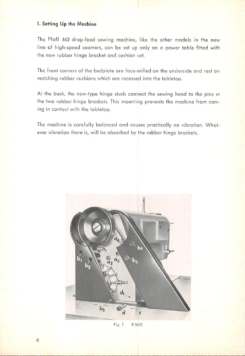
1. Setting Up the Machine
The Pfaff 463 drop-feed sewing machine, like the other models in the new
line of high-speed seomers, con be set up only on o power table fitted with
the new rubber hinge bracket
and
cushion set.
The front corners of the bedplate
matching
rubber
cushions which
are
face-milled on the underside and rest on
are
recessed into the
tabletop.
At the back, the new-type hinge studs connect the sewing head to the pins in
the two rubber hinge brockets. This mounting prevents the machine from com
ing in contact with the tabletop.
The machine is carefully balanced and causes procticatly no vibration. What
ever vibration there is, will be absorbed by the rubber hinge brackets.
Fia.
1
Re(S42
Page 6
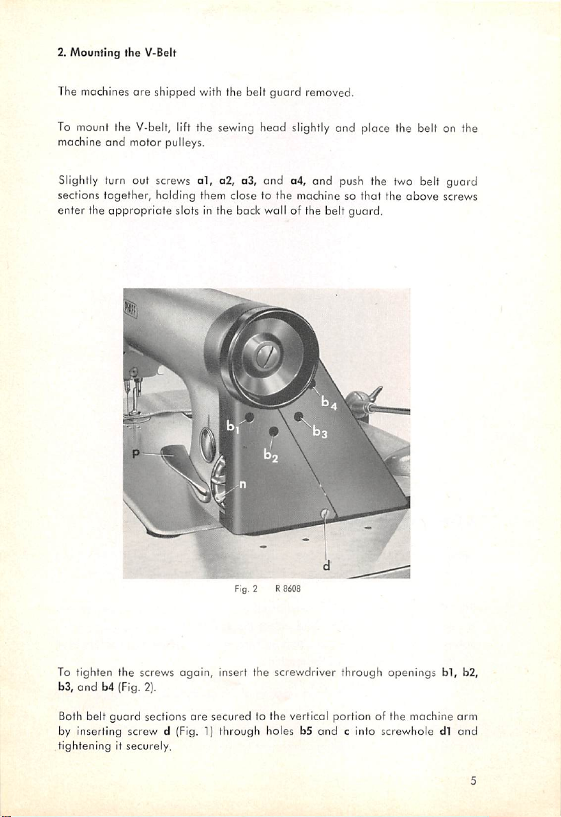
2. Mounting the V-Belt
The machines ore shipped with the belt guard removed.
To mount the V-belt, lift the sewing head slightly and place the belt on the
machine
and
motor pulleys.
Slightly turn out screws
sections together, holding them close to the machine so
ol,
a2, a3, and a4, and push the two belt guard
that
enter the appropriate slots in the back wall of the belt guard.
the
above
screws
Fig. 2 R8608
To tighten the screws again, insert the screwdriver through openings
b3,
and
b4 (Fig. 2).
Both belt
by inserting screw d (Fig. 1) through holes b5
tightening it securely,
guard
sections
ore
secured
to the vertical portion of the machine
and
c into screwhole dl
bl,
b2,
arm
and
Page 7

Fig. 3
RSd-iS
3. Test-Running the Machine
Before you tesf-run the mochine, carefully remove all dirt which may have
accumulated in transit. Use only a brush
The
Pfoff
463
must
neverberinsedorcleaned
a
donger
solves the greose. For the
for the
that
regular
the cleaning fluid enters the sealed-for-life
same
reason,
servicing of the machine.
and
a cleaning rag for this purpose.
with
kerosene
because
bearings
there
and
dis
kerosene or gasoline must not be used
Never attempt to eliminate hard working of the machine by squirting oil freely
into the bearings which, you believe, may be responsible for this fault. If oil
enters the sealed-for-life bearings, the grease will be thinned
the
bearings,
thus eliminating
permonent
lubrication.
and
flung out of
is
Page 8

4. Winding the Bobbin
The new high-speed seamer is fitted with a bobbin winder which is incor
porated in the face cover rother than mounted at the balance-wheel end, as
customary. Arranged at a convenient height, it is easy to operate end enables
the operator to wind bobbins
quickly
and neatly.
The bobbin winder driving
motion
emanates from the take-up crank. When the
bobbin winder is engaged, driving crank F at the rear end of spindle 17 is
pushed into the circular path of stud K which engages the crank and in this
way drives the bobbin winder (Fig.3).
The bobbin winder spindle is carried in a self-lubricating sinter-metal bearing
which requires no additional lubrication. To
engage
the bobbin winder, simply
depress stop latch a located above the bobbin winder spindle (Fig. 5). This
action causes the spindle to move slightly to the right in which position it is
Fig. 4
R
8928
Page 9

retained
until
sufficient
thread
has
been
wound on the bobbin pushes the com up
wound
and
on
the
bobbin.
The
thereby stops the bobbin winder.
thread
amountofthread
The
to be wound on the
bobbin
can be
regulated
by loosen
ing screw b and setting cam a higher or lower, as may be required. Set the
cam higher for more
Figs. 4
and
5 show how to
Place the spool of
thread
the
stand,
from spool11up
downtothread
thread,
thread
guide
or lower, for less
guide
the
thread
on spool pin 11
and
through the top
12 on
the
rear
thread.
to the
bobbin
winder.
and
bobbin 16 on spindle 17. Lead
thread
guide
of the threod
arm
cover,
through
thread
retainer
13 below thread guide 2, through thread guide 14 and around thread tension
15tobobbin
16.
T"
PFAFI
To facilitate
bobbin 16 first,
threading,
and
then to lead the
if is
recommended
ing on the material to be sewn, the
Fig. 5 R
thread
thread
8929
to wind a few clockwise turns on the
around
thread
tension 15. Depend
should be wound tighter or looser.
Page 10

The thread tension is regulated by turning thumb nut 18 back of the tension
discs. Turn
looser
tension.
the
nut
counter-clockwise
for a
tighter
tension,
or clockwise for a
If the threod should pile upatone
tension stud. The set screw securing this stud in position can be reached from
below.
5. Threading the
Needle
end
of the bobbin, adjust the position of the
Because of the high speed of the seamer the smooth possoge of the thread to
the needle is especially importont.
Lead the thread from spool pin 1 up to the top thread guide of the thread
stand and down to thread guide 2. It is recommended to lead the thread first
through the vertical hole from top to bottom and then through the transverse
hole of the guide, as shown in Fig. 4 and 5, in
order
to prevent it from snarl
ing up on the guide and breaking,
Now lead the thread through two or three holes of thread retainer 3, as may
be required,
clockwise
around and between tension discs 4, through thread
check spring 5, under stock threod regulator 6, through thread guide 7, from
right to left through the hole in take-up lever 8, through thread guides 7 and 9
and from left to right through needle eye 10.
6. Regulating the Stitch Length
The stitch length is regulated by means of stitch length control n
large diameter of this control
regulation. When control n is turned by one tooth, the
by
Vfii".
The stitch length is indicated on the teeth in millimeters.
mokes
for an exceedingly fine
stitch
(Fig.
6). The
stitch
length
length is increased
Fig. 6 R8607
Page 11

In
ordertoovoid
stitch
length
disco(Fig.
length.
control
6).
This
that
the
n has
disc
mustbepressed
stitch
been
length
provided
setting
willbedisturbed
withalocking
back
slightly
while
deviceinthe
when
setting
sewing,
form
the
stitch
of
Finger-tip control p serves to reverse the direction of feed and is used for
tacking.
stitches of the length set.
When
actionand the
If
forword to backward sewing.
Upon
stitch
is
then
7. Liftingthe Presser Bar
Since
the
mechonism
To mount the knee lever, push it over the lower end of vertical shaft r under
the
place
coupling sleeve q
When
leverpis
leverpis
desired,
special
length
desired
released,
machine
the
machine
request,
limiting
for
backtacking
the
device
limitedbyturningingrub
the arm standard of the
rear
edgeofthe
in the machine arm so that it isnot visible on the outside.
tabletop.
ofter
tronsverse
bed
The
leverisheldinplacebyangular
driving
(Fig.
7).
pressed
resumes
willbefitted
plate,itwas
down,
the
the
directionoffeedisinstantly
forward
stitching.
withasmall
Pfaff
463
high-speed
for
backward
the
endsofseams.
screw
new
sewing
Sof
crankRon
high-speed seamer has been set closer to
possibletoenclose
pinuhas
entered
machine
sewsinreverse,
treadle
seamer can be
if a shorter
The
lengthofreverse
shaftL(Fig.
bracketswhich
the
cutoutstin
reversedbyspring
for
switching
fitted
backward
10).
the
presser
the
bock-
making
from
with
stitch
stitches
bar
lifting
snaps
into
right-angled
a
is
When
the
coupling
bracketsmustbecompressed
Motionistransmitted
crank,aconnection
A
small
hond
lever
in
its
highest
after it has been raised by knee action
10
position.
sleeveispushed
to open it
from
the
vertical
and a
bellcrank
Cat the
back
This
leverisflicked
of the
shaft
lever
(Fig.
onto
slightly.
to the
which
machine
to the
9).
the
end
of the
presser
raises
the
servestolock
lefttoretain
shaft,
resilient
footbymeans
presser
foot.
the
presser
the
presser
of a
foot
foot
Page 12

Fig. 7 Attoching the knee lever
R&408
To facilitate the tilting bock of the sewing head without removing the knee
lever completely, the knee lever rock shaft is no longer screwed to the ongulor
sleeve, but rather held in place by a spring-loaded pin. As a result, the knee
lever can be pulled forward off the shaft with a slight jerk.
A new feature of the knee lever is its hinged foam-rubber-podded knee plate
which adapts itself well to the shape of the leg. If desired, the knee plate can
be locked by tightening a square bolt.
8. Regulating the Pressure on the Material
A
powerful
flat spring in the
machine
arm
exerts
the necessary pressure on the
sewing foot. The amount of pressure is regulated by turning a small set screw
which can be reached by inserting a screwdriver through the hole 19 at the
right of the spool
pressure (Fig. 4).
9.
Lubrication
pin.
Turn
the
screw
in for more pressure, or out, for
less
Recent advances in the design of needle beorings hove mode it possible to
ensure satisfactory permanent lubrication of this new high-speed sewing
machine without the use of an
automatic
lubrication system.
11
Page 13

Since the use of sealed-fcr-IIfe bearings does not require the machine to be
oiltight, the incorporation of various feeding
accomplished.
to this high-speed sewing machine.
The incorporotion of sealed-for-life boll ond needle bearings requires the use
of 0 reservoir oiling system merely for the sewing hook. From o reservoir built
This
feature opens a practically unlimited
mechanisms
Fteld
can be easily
of application
into the machine arm, oil is fed to the sewing hook through a plastic oil tube.
The oil flow is controlled by shut-off valve V which is built into the oil tube.
When the machine is running, the stud of centrifugal switch F on the hook
shaft
actuates
same valve prevents oil from seeping out when the machine is inoperative.
the valve stem
and
opens
hook lubrication shut-off valve V. The
Theoil level con be inspected through the oil sight glass. Ifit is below the mark
on the oil sight glass, the reservoir should be refilled by inserting the spout of
an ordinary oil can into the small hole v above the oil sight gloss.
The flow of oil to the sewing hook con, in addition, be regulated by screw w
(Fig. 8). Turn this
screw
in for less oil,orout,
for
more
oil.
The correct setting con be obtained through the following test:
Remove
ing.
needle plate and feed dog and place a sheet of paper over the open
Run
the machine for about ten seconds. The setting is correct if two thin
lines of spray oil have appeared on the paper. Adjust the flow of oil at screw w
to suit special
operating
conditions (Fig. 8).
0
fig.
8 R 8603
12
Page 14

In
conlrasttothe
end of the
machine
sealed-for-life
which
requirenolubrication
boll
and
needle
of all,
lubricated from the hook oil reservoir by means of a
(Fig. 9).
bearingsofthe
take-up
wick
enclosed in a tube
needle-bar
lever
linkzis
:fi:
rv.i
;a.i
Fig. 9
Face
cover
removed
Flat spring B exerls pressure on the presser foot,
highest position ofter it hos
The oil supply in Ihe foam-rubber-lined reservoir x ond y for Ihe upper and lower needle bar
bushings should be replenished more or less frequently according to the time the machine is in
operation
From
eoch
doy.
the foam-rubber-lined reservoirs x and y, oil is supplied to the upper and
been
raised by Ihe knee lever.
Lever
C serves to retain ihe presser foot in its
R
8605
lower needle bor bushings (Fig. 9). The oil supply in these reservoirs should be
replenished frequently, particularly whilethe machine is being run in.
13
Page 15

The feed driving and feed regulating
mechanisms
as well as the hook shaft
driving gears in the gear cose ore lubricated by means of two oil-soaked foam
rubber
sheets.
To change the oil (once a year is sufficient), tilt back the machine and remove
the
gear
case cover. The foam rubber sheet should be woshed thoroughly in
order to remove the metal grit which has accumulated on it.
In most
(Nos.
same
(No. 120110).
instances,
69299
oil as is used in the hook lubrication system, namely 2.7°E/50°C
and
however,
69302)
it will be
better
to insert new
foam
which must be soaked with 17 oz, or 160 ccm, of the
rubber
sheets
When you replace the foam rubber sheet, make sure that it fits properly. The
large spur gear should run freely in the cutout of the sheet. The oscillating feed
rockshaft is grease-lubricated. Grease nipple N closes the left end of the shaft
(Fig. 8).
When screwing on the gear cose cover, make sure that the gasket is not
defective and that the
from
seeping
Note
out.
screws
are lightened
uniformly
in order to prevent oil
In replenishing the oil supply for the sewing hook, take care that no air bubble
forms in the oil line to the centrifugal switch because this would interrupt the
flowofoil.
The simplest procedure for removing an air bubble from the oil line ahead of
the centrifugal
switch
is as follows:
Pull
the left end of the oil tube off the
nipple and hold it up so that the air bubble rises to the surface. Then replace
the oil
tube
on the nipple carefully.
An air bubble which may hove formed in the left section of the oil tube is of no
consequence because itcan escape
14
through
the regulating valve
(Fig.
10).
Page 16

s
Fig. 10 Bottom view of the Pfoff 463
The
gear
cose cover and the foom
rubber
sheet
are
removed.
R
8606
The lower drive shaft carries the feed driving eccentric and the hook shaH driving gear in the
gear
case, ond the mechanical opener driving mechanism and the feed lifting eccentric near its
left
end.
The hook shofi carries centrifugal switch F whose stud pushes the valve s'em to the right and
opens hook lubrication shut-off valve V. The same valve prevents the oil from seeping out when
the
machineisinoperative.
The stitch length setting is transmitted from the stitch length control to
in the
gear
case,
the feed rock
feed
bar.
Upon
special
request, the machine can be fitted with o stitch length limitoting device for back
ward
sewing. To limit the length of the reverse stitch, turn in
shaft,
and an
adjustable
crank which, in turn, transmits it to the
shaft
L, a
crank
grub
screw S of crank R on shofI L.
mechanism
15
Page 17

Fig. 11 R8604
Page 18

No.
PFAFF
10769
engl. R962 Printed in Germany
 Loading...