

Page 1
®442-R
Service
441
442-0
Manual
-O
Pfaff, D
6750
Kaiserslautern,
Postfach
3020/3040,
Telex:
045753
Page 2
Important
note:
ThisServiceManual applies also tothe Raff 441-0 and 442-0. Deviations in the illustrations do not
affect
the
When adjusting a single-needle machine,
adjustment of the machines.
needle and the left sewing hook. A separate Service
Pfaff
441-R
(0)-705/03: -755/03.
Tools,
gauges
and
other
items required for adjusting
1
setofscrewdrivers
1
set
ofwrencheswithopeningsfrom 7 to 14 mm wide
1
set
of alien keysfrom 2 to 6 mm
1 feed dog
1 adjusting
1 C-clamp,
1
metal
gauge,
gauge,
part
rule
with
part No.
part No. 91
No.
880137/00
blades
from2to10mm
91-129995-05
-129573-91
The
Sen/ice
simply
ignore the adjustment procedure for the left
Raff
wide
Manual is
based
Manual
machines
on a two-needle machine.
is available for adjusting the
442-R, 441-0
and
442-0
1 wrapper of needles: system 134 (for7 mmfabric clearance)
system
134-35
(for 9 mm fabric clearance)
2 strips of white
paper
Sewing thread and testing material
Technical
Maximumsewing
Balance
Drive:
data
speed:
5000 s.p.m.
wheel:65mm
eff.
dia.
clutchmotor0,550 kW(% HP)
lever-operated Stop motor 0,550 kW(% HP)
electronic-stop-motor 0,550 kW(% HP)
Needle system: 134 (for7 mmfabric clearance)
134-35
Fabric
clearance:7or9mm
(for 9 mm fabric
clearance)
Page 3
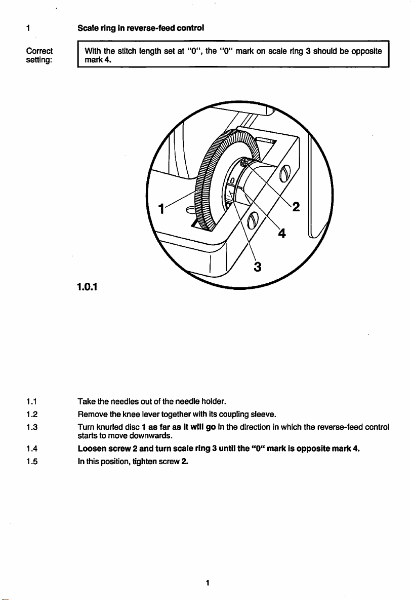
Scale
ringinreverse-feed
control
Correct
setting:
With the stitch length
mark
4.
1.0.1
setat"0",
the
"0"
mark on scale ring 3 should be opposite
1.1
1.2
1.3
1.4
1.5
Take
the
needles
outofthe
Remove
Tum
startstomove
Loosen
the
knurled
screw2and
knee
levertogether with its coupling
disc1as
downwards.
Inthis position, tighten
needle
holder.
farasit willgoin
turn
scale
ring
screw
2.
the
3 until
the
sleeve.
direction in which
"0"
markIsopposite
the
reverse-feed
mark
control
4.
Page 4
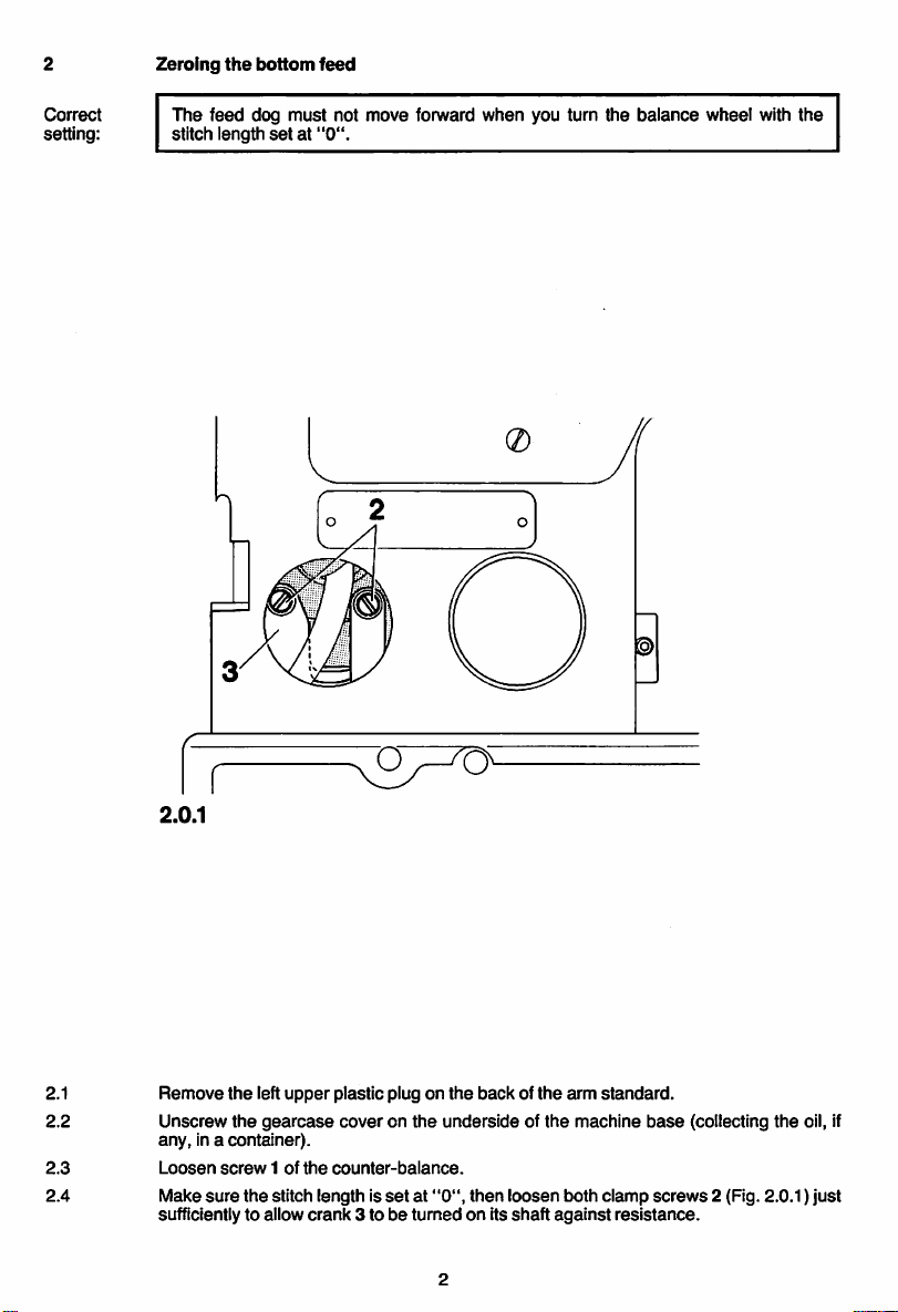
Zeroing
the
bottom
feed
Correct
setting:
The
feed
stitch length
dog
must
setat"0".
not
move
forward
when
you turn
the
balance
wheel
with
the
2.1
2.2
2.3
2.4
2.0.1
Remove
Unscrew
any,
Loosen
Make
the
left
upper
the
gearcase
in a container).
screw1of
sure
the
stitch length is
sufficiently to allow
plastic plug on
coveronthe
the
counter-balance.
crank
3 tobeturnedonits
undersideofthe
setat"0",
the
backofthe
then
loosen
shaft
arm
machine
both
against
standard.
base
clamp
screws
resistance.
(collecting
2 (Fig. 2.0.1)
the
oil, if
just
Page 5
2.5
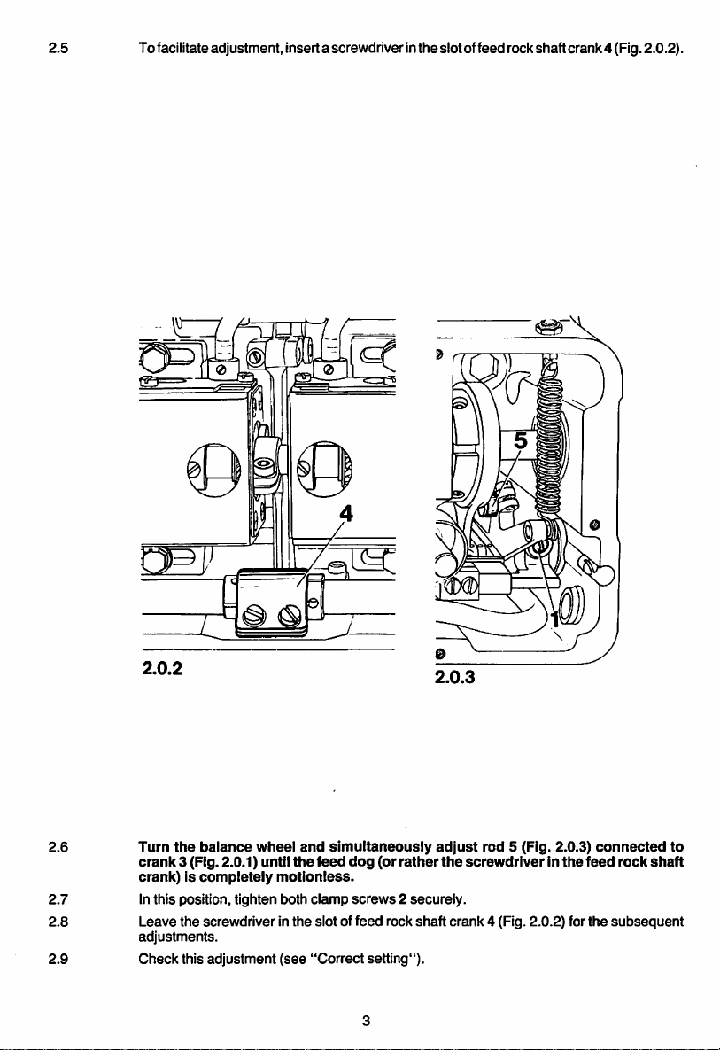
Tofacilitateadjustment, inserta screwdriver in the slot offeed rock shaft crank4 (Fig. 2.0.2).
2.0.2
2.6
2.7
Turn
the
crank
balance
3 (Fig. 2.0.1) until
crank)Iscompletely
Inthis position, tighten both
wheel
motionless.
and
simultaneously
the
feed
clamp
2.8 Leave the screwdriverin the slot of
adjustments.
2.9
Check
this
adjustment
(see
"Correct
2.0.3
adjust
dog
(or
rather
screws2securely.
feed
rock shaft crank 4 (Fig. 2.0.2) for
setting").
rod
the
screwdriverinthe
5 (Fig. 2.0.3)
connected
feed
rock
the
subsequent
to
shaft
Page 6
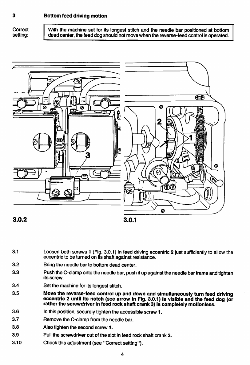
Bottom
feed
driving
motion
Correct
setting:
With the machine
set
for its longest stitch and the needle bar positioned at bottom
deadcenter, the feed dog should not move when the reverse-feedcontrol is operated.
J
3.0.2
3.0.1
3.1 Loosen both screws 1 (Fig. 3.0.1) In feed drivingeccentric 2 just sufficientlyto allow the
eccentric to be turned on its shaftagainst resistance.
3.2
Bring
the
needle
bar
to bottom
dead
center.
3.3 Pushthe C-clampontothe needle bar,pushitupagainstthe needle barframeandtighten
its
screw.
3.4
Set
the
machine for its longest stitch.
3.5 Movethe reverse-feed control up and down and simultaneously turn feed driving
eccentric 2 until its notch (see arrow in Fig. 3.0.1) is visible and the feed dog (or
rather
the
screwdriverin feed rock
shaft
crank3) is completely motionless.
3.6 Inthis position, securely tighten the accessible screw 1.
3.7
3.8
3.9
Remove
Also tighten
Pull
the
the
screwdriver
C-clamp
the
second
from
screw
outofthe
the
needle
1.
slotinfeed
bar.
rock
shaft
crank
3.
3.10 Check this adjustment (see "Correct setting").
Page 7
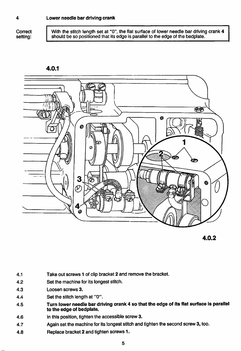
Lower
needle
bar
driving
crank
Correct
setting:
With the stitch length
shouldbeso
4.0.1
positioned that its
set
at "0", the flat surface of lower needle bar driving crank 4
edge
is parallel to
the
edgeofthe
bedplate.
4.0.2
4.1
4.2
4.3
4.4
4.5 Turn lower
Take
out
screws
1 of clip bracket 2
Set
the
machine for its longest stitch.
Loosen
screws
3.
Set
the
stitch length at
needle
to
the
edgeofbedplate.
bar
"0".
driving
and
remove
crank4so
that
the
the
bracket.
edge
of its flat
surface
4.6 Inthis position,tighten the accessible screw 3.
4.7 Againset the machineforits longeststitchand tightenthe second screw3, too.
4.8 Replace bracket 2
and
tighten
screws
1.
is parallel
Page 8
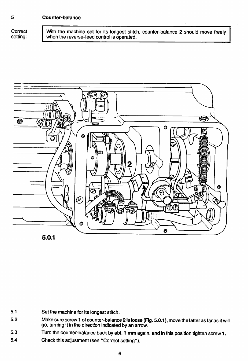
Counter-balance
Correct
setting:
With
the machine set for its longest stitch, counter-balance 2 should move freely
when
the reverse-feed control is operated.
5.1
5.2
5.3
5.4
5.0.1
Set
the
machine for its longest stitch.
Makesure screw 1 ofcounter-balance 2 is loose (Fig.5.0.1), movethe latter as far as it
go, turning itinthe direction indicated by an arrow.
Turnthe counter-balanceback byabt. 1 mmagain,and inthis
Check this adjustment
(see
"Correct setting").
position
tighten
screw1.
will
Page 9
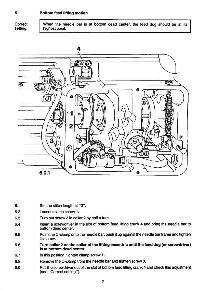
Bottom
feed
lifting
motion
Correct
setting:
When the needle bar is at bottom
highest
point.
n
W
dead
center, the feed dog should be at its
6.1
6.2
6.3
6.4
6.5
6.6
6.7
6.8
6.9
Set
the
stitch length at
Loosen
clamp
Turn out
screw
Insert a screwdriver in
bottom
dead
center.
Push
the C-clamp onto
its
screw.
Turn
coiiar2on
isatbottom
dead
"0".
screw
1.
3 in collar 2 by half a turn.
the
the
the
collarofthe
center.
Inthis position, tighten clamp
Remove the C-clampfrom
Pull
the
(see
screwdriver
"Correct
outofthe
setting").
slot of bottom
needle
bar, push itup
lifting
screw
1.
the
needle
bar
slot
of bottom
feed
lifting
eccentric
and
tighten
feed
crank4and
against
until
screw
lifting
the
needle
the
feed
3.
crank4and
bring
bar
dog
check
the
needle
frame
and
(or
screwdriver)
this
adjustment
bar
tighten
to
Page 10
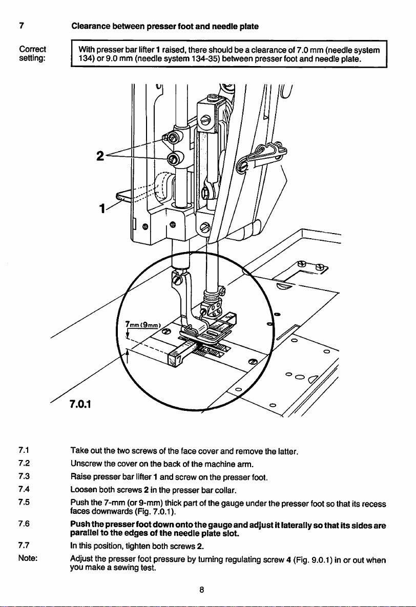
Clearance
between
presser
foot
and
needle
plate
Correct
setting:
Withpresser bar lifter1 raised, there shouid be a ciearance of 7.0 mm (needie system
134) or 9.0 mm (needle system 134-35) between presserfootand needle plate.
7mm(9mm)
f
7.1
7.2
7.3
7.4
7.5
7.6
7.7
Note:
Take
out
the
two
Unscrew
Raise
the
presser
Loosen both
screwsofthe
coveronthe
bar lifter1 and screw on the
screws
2 inthe
face
backofthe
presser
cover
and
machine
bar collar.
remove
arm.
presser
foot.
the
latter.
Push the 7-mm (or9-mm)thickpart ofthe gauge under the presser footso that itsrecess
faces downwards (Fig.7.0.1).
Push the presserfoot downonto the gaugeand adjustItlaterallysothat its
parallel to
the
edgesofthe
needle
plate
slot.
sides
are
Inthis position, tighten both screws2.
Adjust
the presser footpressure by
you
make
a sewing test.
turning
regulating
screw4
(Fig.
9.0.1)inoroutwhen
Page 11
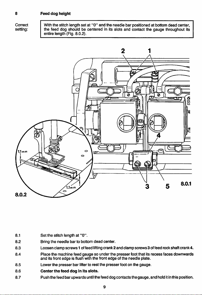
Feed
dog
height
Correct
setting:
Withthe stitch length
setat"0"
and
the
needle
bar
positioned at bottom
dead
center,
the feed dog should be centered in its slots and contact the gauge throughout its
entire length (Fig. 8.0.2).
2
8.1
8.2
Set
Bring
the
stitch length at
the
needle
8.3 Loosenclamp
8.4
8.5
8.6
8.7
Place
and
Lower
Center
Push
the
its front
the
the
the
feed
machine feed
presser
screws
edge
feed
bar
"0".
bar
to bottom
dead
1 offeed liftingcrank 2
gaugesounder
is flush with
bar
doginits
upwardsuntil
lifterto
the
rest
slots.
the
center.
front
the
presser
feed dog
and
the
presser
edgeofthe
foot on
contacts
clamp
foot that its
needle
screws
the
the
3 offeed rock shaftcrank4.
recess
faces
plate.
gauge.
gauge,
and
hold itinthis position.
downwards
Page 12

8.8 Turn
eccentric
in
contact
protrudes
bushing5located
with
the
1.1mmfrom
gauge
the
8.9 inthis position, tightenclamp
in
its
slots.
8.10
8.11
Check
Raise
this adjustment
the
presser
bar
(see
lifter and remove the
under
throughout
needle
screws1and
feed
its
plate
3, making
"Correctsetting").
rock
entire
surface.
gauge
shaft
length
(Fig. 8.0.2);
sure
that
from under
crank
the
feed dog is still
the
4 until
the
presser
the
foot.
feed
feed
dog
centered
dog
is
now
10
Page 13

Correct
setting:
Centering the
With
spective needle holes. (ItIs recommended to Inserttwonew needles)
needlesinthe
the stitch length set at "0", the needles should be centered exactly In the re
needle holes
9.1 Unscrew the cover on the back of the machine arm
9.2
9.3 Set the stitchlengthat"0", and
9.4 inserttwoneedles
9.5 Loosenscrew11ncollar2 onthe needle bar
Unscrew
the
needle
the presser footandthe thread tensionbase plate.
bring
the needle barto topdead center.
Into
system).
the needle holderso thattheir
driving
aperture (see arrowin Fig.9.0.1).
9.6
Aiso
loosen
clamp
screw3 inthe needlebar
driving
11
near
the balance wheel.
long
groovesface each other(note
shaft
which
isaccessiblethroughthe
crank
(Fig.
9.0.3).
9.0.2
Page 14
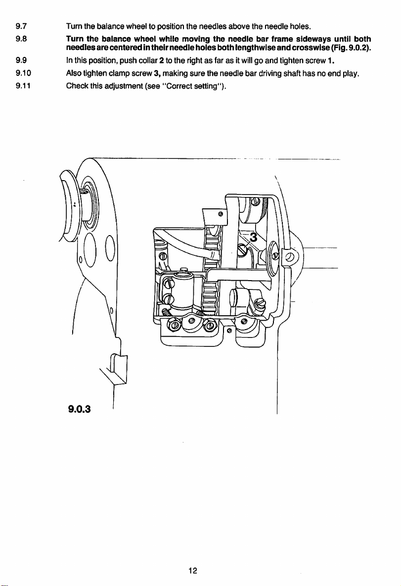
9.7
9.8
Turn
the
Turn
needles
balance
the
balance
are
centeredintheir
wheel
wheel
to position
while
needle
the
needles
moving
holes
the
above
needle
both
9.9 Inthis position, push coilar 2 to the rightasfarasit
sure
9.10 Also tighten clamp screw 3, making
9.11
Check
this
adjustment
(see
"Correct
the needle bar drivingshaft
setting").
the
needle
bar
lengthwise
wiii
frame
and
go and tighten screw 1.
holes.
sideways
crosswise
has
until
(Fig. 9.0.2).
no end play.
both
9.0.3
12
Page 15

10
Preliminary
adjustmentofneedle
bar
height
Correct When the needle bar Isat top
dead
center, there should be a clearance of 17 mm be
setting: tweenneedle pointand needle plateon
on
ModelLmachines.
Model
S =33mm
Model
L =38mm
Model
S machines,and a clearanceof22 mm
needle
bar
bar
stroke
stroke
needle
10.0.1
10.1 Bringthe needle bar to top
dead
center.
10.2 Loosen hexagon screw 1 inthe needle bar connecting stud.
10.3
Adjust
the needlebar vertically untilthereis a clearanceof17mmbetweenneedle
pointand needle plateon
machines.
Make
sure
the
Model
S machines,or a ciearance of22 mmon
needie
barisnot
turnedinthe
10.4 Inthis position, tighten hexagon screw 1.
13
17mm(22mm)
process.
10.0.2
Model
L
Page 16

11
Hook timing,
hook-to-needle
clearance
and
needle
bar
height
Correct
setting:
Withthe stitch length
center(needle rise position)each hookpoint should be exactly oppositethe center line
of the respective needle, the lateral clearance between hook point and needle being
0.1 mm. Also, Inthis position, the hook points should be positioned 0.8 mm abovethe
top
edge
of the respective
setat"0"
needle
and the needlebar positioned 1.8 mm
eye.
past
bottom
dead
\
11.0.2
11.1
Set
the stitch length at
"0".
11.2 Unscrewthe needle plate and the feed dog.
11.3
11.4
Loosen
alien
and alien screw 2 between both bevel gearcases.
screw1,
Loosen
both
screws3,which
which
Isaccessible
areaccessible
14
through
through
11.0.3
the holeinthe
the
holes
bevel
inthe
gearcase
bevel
11.0.1
cover,
gearcases.
Page 17
11.5
Loosen
screws
4 of
the
bobbin
case
opener
eccentrics.
11.6 Also loosen hexagon screws 5 of the hook bearing brackets.
11.7 Bringthe needle bar to bottom
11.8
Push
the 1.8-mm-thick blade of
dead
the
center.
gauge
onto
the
needle
bar immediately below its
lower bearing, push the C-clamp up againstthe blade and tighten its screw.
11.9 Pull out the gauge and turn the balance wheel in its normal direction
contacts
the
needle
bar
bearing.
until
the C-clamp
11.10 Turn
both
the
hooksontheir
respective needle. Inthis position(needle rise position), the hook points should be
shaftssothat
their
points
are
opposite
the
center
positioned0.8 mmabove the top edge ofthe respective needle eye. Ifnecessary, adjust
the
needle
bar height.
11.11
Adjust the hook bearing brackets laterally until there is a clearance of 0.1 mm be
tween
the
hook
points
and
the
needles.
11.12 Inthis position, securelytighten hexagon screws 5.
11.13 Adjustthe leftpart ofthe main driveshaft so that the clutch has a playof0.5 mm.
11.14 Inthis
11.15 Tightenone each ofscrews 4 ofthe bobbin
set
too
position,
close
tightenalienscrews 1 and 2, makingsure thatthe bevelgears are neither
nor
have
too much play.
case
opener eccentric.
11.16 Push the bushings up against the bevel gears and tightenbothscrews 3 on each.
11.17 Remove the C-clamp from the needle bar.
11.18 Check this adjustment
11.19 Do not tighten the second screws4
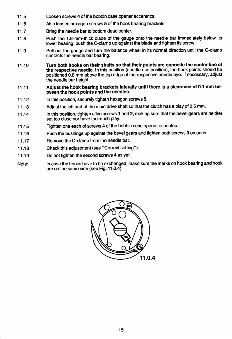
Note: In
case
the hooks have to be exchanged, make sure the marks on hook bearing and hook
are
on the
same
side
(see
"Correct setting").
(see
Fig. 11.0.4)
as
yet.
iine of
15
Page 18

12
12.1
Bobbin
case
Right bobbin
openers
case
opener
eccentric
Correct
setting:
When
thetake-upleverisat
shouldbeexactly
atitsrear
bottom
deadcenter,shaft3ofthe
point
ofreversal,asseeninthe
a
right
direction
bobbin
caseopener
offeed(see
arrow).
12.1.1
12.1.2
12.1.3
12.1.4
12.1.5
12.1.6
12.0.1
Screwon the feed dog.
Also
screwontheneedle
the
appropriate
Loosen
slotsonthe
screw1in
the
right
Turnthe balancewheelto
Turn
the
right
bobbin
its rear point of reversal
Inthis
position,
case openereccentric 2on its shaft
tighten
screws1 securely.
plate,
making
underside
bobbin
case
bring
the take-up leverto
(see
arrow).
16
surethatthelugsof
ofthe needle
opener
plate.
eccentric,
bottom
both
bobbin
which
was
dead center.
until
case bases enter
tightened
shaft3 is
previously.
exactly
at
Page 19

12.2
Correct
setting:
Left
bobbin
case
opener
eccentric
When
the
take-up lever Isat bottom
dead
center,shaft 6 of
shouldbe exactlyat itsfront point ofreversal,asseen
the
left bobbin
inthe direction offeed
case
(see
opener
arrow).
12.2.1
12.2.2
12.2.3
Loosen
Turn
Turn
its
front
screw
4 in
the
balance
the
left
bobbin
pointofreversal
the
wheel
left bobbin
to bring
case
opener
(see
case
opener
the
take-up
eccentric5on
arrow).
Inthis position, tighten
eccentric, which
leverto bottom
its
shaft
was
tightened previously.
dead
center.
until
shaft6is
screw
exactly
4 securely.
at
17
Page 20

12.3
Right
bobbin
case
opener
Correct Whenshaft 1ofthe rightbobbin
setting:
as
seen
inthe direction of feed,
the lugofthe rightbobbin
case
case
opener isat its rear pointofreversal (see arrow),
there
base
should be a
and the rear
clearance
edge
of 0.3 to 0.5 mm
ofthe needie plate slot.
between
12.3.1
12.3.2
12.3.3
12.3.4
12.3.5
12.3.6
12.0.2
12.0.3.
Bring
the
needle
bar
Turn
the
balance
to bottom
wheel
inits
dead
normal
center.
direction
until
shaft1ofthe
right
bobbin
case
opener
is at its rear pointof reversal (see arrow).
Loosenclampscrew 2 ofthe connecting crankonthe
Reposition
the
connecting
crank
on its
shaftsothat
right
shaft1.
there
is a
clearance
of 0.3 to
0.5mmbetweenthe lugofthe rightbobbincase base andthe rearedgeofthe needle
plate
slot.
In
this
position,
Checkthis adjustment(see "Correctsetting").
tighten
clamp
screw2,making
surethatthe
18
connecting
crank
isnot
tilted.
Page 21

12.4
Left
bobbin
case
opener
Correct
setting:
When shaft 3 of
as
seeninthe
the lugofthe leftbobbin
12.4.1 Bringthe needle bar to bottom
12.4.2 Continue turningthe balance wheel inits normaldirection
case
openerIsat its front point of reversal
the
left bobbin
direction of
feed,
case
case
opener
there
base
dead
center.
is at its front point of reversal
shouldbea
clearanceof0.3to0.5mmbetween
and the frontedge ofthe needle plateslot.
until
(see
arrow).
shaft 3 ofthe left bobbin
(see
arrow),
12.4.3 Loosen clamp screw 4 of the connecting crank on the leftshaft 3.
12.4.4 Reposition the connecting crank on its shaftsothat there Is a clearance of 0.3 to
0.5 mm between
plate
slot.
12.4.5 Inthis
position,
12.4.6 Check this adjustment
the
lug of
the
left bobbin
tightenclampscrew 4,
(see
"Correct setting").
case
base
and
the
front
making
sure that the connecting crankisnot
edgeofthe
needle
tilted.
19
Page 22

13
Oil
check
valve
Correct
setting;
When the machine is inits inoperativepositionthere should be a clearance of0.3 mm
betweenactuating lever4 and
together
lever
holeand its
(Fig.
13.0.2).
4and
circlip6.Furthermore,
circlip
should
Also,
lifting
there
lightly
eccentric5 at the
should
bea clearanceof2.0mm
operating
pin8shouldbecenteredinthe
contactthe actuating lever.
13.0.3
point
wherethey are closest
between
actuating
elongated
13.0.1
13.1
13.2
13.3
13.4
13.5
13.0.2
Loosen
both
clamp
screws
1and
push
oil
check
valve
2tothe
right.
Also
loosen
screw
3.
Adjust
actuating lever4so thatthereisa clearanceofabt.0.3mmbetween
at
rest,
and
lifting
eccentric
in this position, tighten screw3.
Repositioncirclip6 so that,whenthe machine is at rest,there is a clearance ofabt.
2.0mmbetweenactuating lever4 and circlip6.
5.
20
it,when
Page 23

13.6
Loosen
screws
7.
13.7 Push operating pin 8 toward the right until
ting pin 8 is centered inits elongated hole.
13.8
13.9
13.10 In this position, tighten clamp
13.11
13.12 Carefully
13.13 Replace the
In this position, tighten
Reposition
actuating
Screw
oil
check
lever
4. Make
on the lateral
clean
the
gasket
gearcase
screws
7.
valve2so
sure
gearcase
that
operating pin8 is stillat the point where pressure is felt.
screws
1.
cover.
face on
the
gearcase
cover and screw itdown, tightening its fivescrews crosswise.
pressure
the
is felt. Adjust bracket 9 so that
circiiponoperating
and
the
pin 8 lightly
gasketofthe
gearcase
opera
contacts
cover.
21
Page 24

14
Tension
release
mechanism
Correct
setting:
14.0.1
When
apart.
the
presser
® J ©
bar
lifter is raised, both
14.0.2
tension
discs
shouldbeat
least
0.5
mm
14.1
14.2
14.3
14.4
14.5
14.6
Raise the presser bar
Screw tension
Checktomake
ifthe
tension
piate1againandbend
After
the adjustment, replace tension base piate1.
base
plate 1.
sure
both
discsare
lifter,
then screw onthe presser
tension
discsareatieast0.5mmapart.
either
toofar apartor tooclose
tension
release
lever2accordingly.
Checkthisadjustment (see "Correctsetting").
22
foot.
together,
remove
tension
base
Page 25

15
Knee
lever
play
Correct
setting:
When operated,
foot
starts
rising.
the
knee
lever should have a small amount of play before
the
presser
15.0.1
15.1 Push the knee lever jointonto the vertical knee lever shaft, push it upwards and turn itto
the rightasfarasitwillgo.
15.2
15.3 Lowerthe presserfootonto the needle plate by means ofthe presserfoot
Insert
the
knee
lever
Into
the
knee
lever
joint.
lifter.
15.4 Loosen locknut1 of the rightstop screw2 and turn the stop screw out a few turns.
15.5 Then turnstop screw 2 inagain
15.6 Inthis position, turn
nutl.
stop
15.7 Check this adjustment
until
the presserfootstarts to
lift
clear ofthe needle plate.
screw2out byone turn and lock itInposition bytightening
(see
"Correctsetting").
23
Page 26

16
Knee
lever
stroke
limitation
Correct
setting:
When the knee lever is
weightand the presserfootshould be
7.0
mm (or 9.0 mm).
fully
operated, the presser bar
lifted
fromthe needle plate bya
lifter
should drop by Its own
little
more than
16.1
16.2
16.3
16.4
16.5
16.6
16.0.1
Loosen locknut1 ofstop screw 2.
Turn
stop
screw2out
Raise
the
presser
presser footand lowerthepresser bar
Move
the knee lever to the right until a noticeable resistance is felt;howeverthe
presser
foot
Hold
the
knee
bar
must
not be lifted off
lever
atthis
a few turns.
lifter,
place
position
the
7-mm-(or
the
lifter
gauge.
9-mm)
again.
thick
blade
andturnstopscrew2inas faras it
ofthe
gauge
back out by one turn, and lock it in place with locknut 1.
Checkthis adjustment (see "Correctsetting").
24
will
under
go,then
the
Page 27
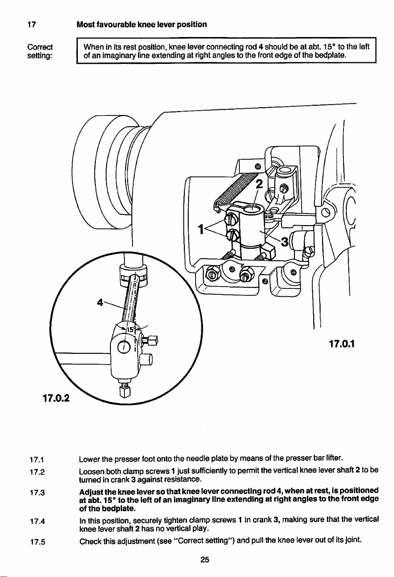
17
Most
favourable
knee
lever
position
Correct
setting:
When
in its
rest
of an imaginary lineextending at rightangles to the front
position,
knee
iever connecting rod 4 shouid be at abt. 15° to
edge
of the bedplate.
the
ieft
17.0.1
17.0.2
17.1
17.2 Loosenbothclampscrews1 just
Lower
tumed
thepresser
in crank 3
foot
ontothe needleplatebymeansofthe presser bar
against
sufficientlytopermit
resistance.
the
vertical
lifter.
kneeievershaft 2 to be
17.3 Adjustthe kneeleverso thatkneeleverconnecting rod4,whenat rest, Ispositioned
17.4
17.5
at abt. 15° to
of
the
In
this
knee
Check
bedplate.
position,
lever
shaft2has
this
adjustment
the
left of an imaginary line extending at right
securely
tighten
clamp
no vertical play.
screws1 incrank3,
(see "Correct setting") and
25
pull
anglestothe
making
surethat the
theknee ieveroutofits
front
joint.
edge
vertical
Page 28

18
Hook
lubrication
Correct
setting:
Afterthe machine has run at
appearopposite each hookon a piece of paper placed vertically behind them.
full
speed
forabout ten seconds, a finetrace ofoilshould
18.0.2
18.1
18.2
18.3
18.4
18.5
18.6
Checkthe
level
density
Turninregulating
out by half a turn.
Turn on the masterswitch and let the machine run about one minute.
Placea pieceofpaper
hasappeared onthepaper
Iftoomuchoilis
hooksomewhat.Iftoo
oil
Isin line
of 0.87
level
at the
oil
with
the uppermark. Use
sightglass and, ifnecessary, topupthe reservoir
kg/dm^.Werecommend
screws
1and2ofthe
vertically
behindthe hooks.Then checktosee ifa finetrace of
opposite
emitted,
turnin
little
oilIsemitted, turnoutthe respectivescrew a
oil
oil
check
each
hook
regulating
withaviscosity
Pfaff
sewing
of16.0
machine
valveasfarasthey
raceway.
screw1forthe righthookor2fortheleft
Checkthisadjustment(see "Correctsetting").
26
mm^/s
oil
No.
will
18.0.1
until
at 50°Cand a
280-1-120
go,
and
then
little.
the
back
oil
144.
oil
Page 29
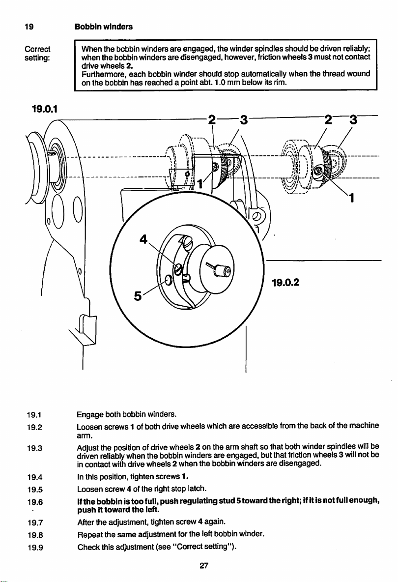
Bobbin
19
winders
Correct
setting:
19.0.1
When the bobbin winders are
when
the
bobbin
winders
drive
wheels
Furthermore,
on
the
bobbin
2.
each
has
are
bobbin winder should
reached
engaged,
disengaged,
a point abt. 1.0 mm below Its rim.
the winder spindlesshould be driven reliably;
however, friction
stop
automatically
19.0.2
wheels3must
when
the
thread
not
contact
wound
19.1 Engage both bobbinwinders.
19.2 Loosen
19.3
19.4
19.5
19.6 If
screws
arm.
Adjust
driven
in
contact
Inthis position, tighten
Loosen
the
bobbinis
pushittoward
1 of both drive wheelswhich
the
positionofdrive
reliably
whenthe
withdrive
screw
4 of
the
too
the
wheels
bobbin
screws
stop
push
winders
1.
regulating
wheels2when
right
full,
left.
are
accessiblefrom the back ofthe machine
2onthearmshaftso that
areengaged,butthat
the
bobbin winders
latch.
stud
5toward
19.7 Afterthe adjustment, tightenscrew 4 again.
19.8 Repeat the same adjustment forthe leftbobbinwinder.
19.9 Check thisadjustment (see "Correct setting").
27
both
winder
friction
are
disengaged.
the
right; ifitis not full
spindles
wheels3
will
will
notbe
enough,
be
Page 30

20
Thread
check
spring
Correct
setting:
The
enter
20.0.1
thread
check
the
material (which
spring should
amounts
have
completed its stroke
to a
stroke
abt.
7 mm long).
when
the
needle
points
20.0.2
Note: Actual sewing conditions may make it necessary to increase or decrease the stroke
ofthe thread check spring.
20.1 Thread the needlesand place a piece offabricunder the presserfoot.
20.2 Operatethe presserbar liftertolowerthe
presser
footonto the material.
20.3 Loosen screw1 inthe elongatedhole ofstop 2.
20.4 Turnthebalancewheeltosewafewstitchesand
20.5
20.6 Inthis
Continue
springtomakeareturn
turning
position,
the
bring
stop2 incontact
baiance
strokeof7
wheelinits
mm.
with
bring
thetake-uplevertoitshighest
normal
directiontocause
thethreadcheckspringand
the
tighten
thread
screw1.
point.
check
20.7 Checkthis adjustment (see "Correctsetting").
28
Page 31
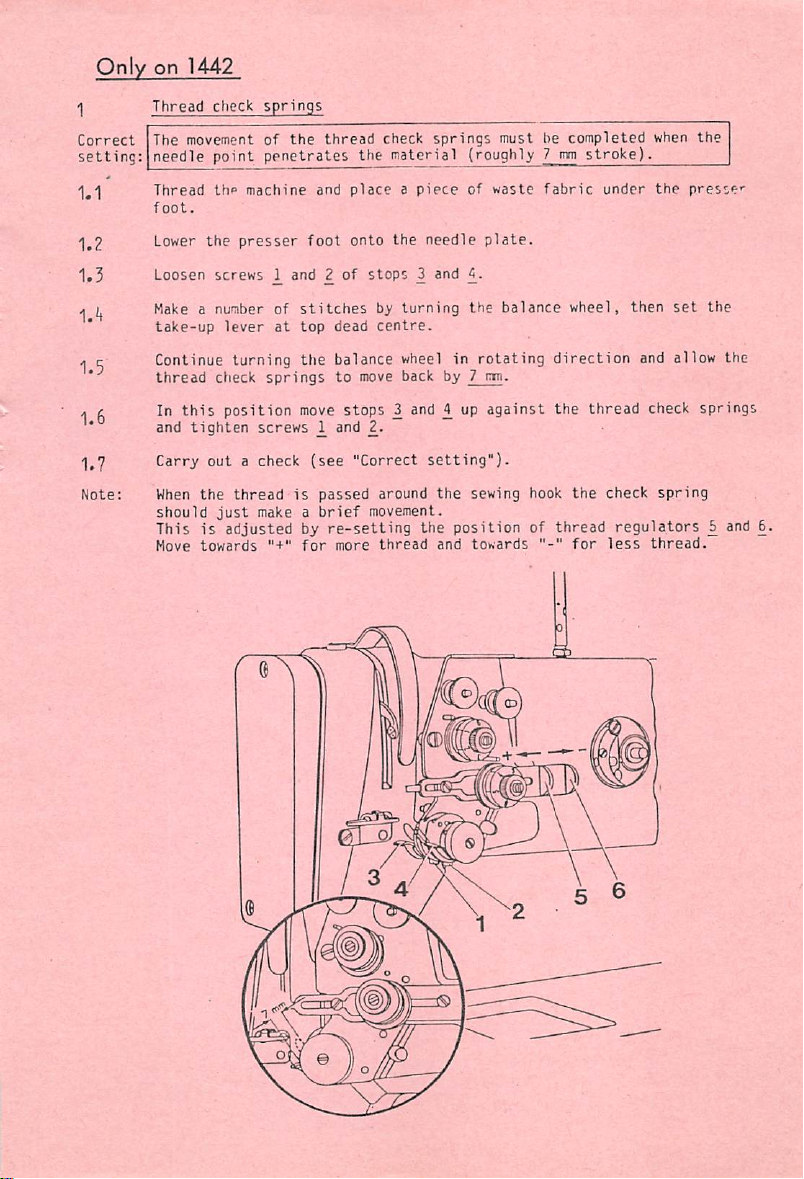
Only
on
1442
Correct
setting:
1.1'
1.2
1.3
l.'t
1.5
1.6
1.7
Note;
Thread
The movementofthe
check
springs
thread
check
springs
must be
completed
needle point penetrates the material (roughly 7mmstroke).
Thread
foot.
Lower
Make a number of
th«»
machine
the
presser
Loosen
screws
take-up
lever
at
Continue turning
thread
check
springstomove
In
this
and
Carry
When
should
This is
Hove
position
tighten
the
out
just
screws
a check
thread
make a
adjustedbyre-setting
towards
and
placeapiece
foot
onto
and 2ofstops
stitches
top
the
move
(see
is
for
b>'
dead
centre.
balance wheel in
stops
and 2.
"Correct
passed
around
brief
movement.
more
thread
the
needle
3 and
turning
back by 7
2 and £ up
setting").
the
the
positionofthread
and
of
waste
plate.
the
balance
rotating
m.
against
sewing hook
towards
fabric
wheel,
direction
the
thread
the
for
under
then
check
regulators
less
when
the
the
presses
set
the
and allow the
check springs
spring
b and 6.
thread.
Page 32

Page 33

21
Final
worksteps
21.1
21.2
21.3
21.4 Make a sewing
Screwonthe
two
coversonthe
backofthe
Replace the left upper plastic plug on
Screwonthe
presser
face
test
foot
pressuresothat
cover.
and
at the
same
the
fabric is fed properly
CONTENTS
1
Scale
ringinreverse-feedcontrol
2 Zeroingthe bottomfeed
3 Bottom
4 Lower
5
6 Bottom
feed
needle
Counter-balance
feed
driving motion
bar
driving
liftingmotion
crank
7 Clearance between presserfoot and needleplate
8
Feed
dog height
9 Centering the needlesinthe needle holes
10 Preliminary adjustmentof
11 Hook
12 Bobbin
13
14
15
16
17 Most favourable
18
19
20
Oil
check
Tension
Knee
Knee
Hook
Bobbin
Thread
timing,
hook-to-needleclearanceand needle barheight
case
openers
valve
release
mechanism
lever play
lever
stroke
knee
lubrication
winders
check
spring
limitation
lever position
needle
bar
height
the
machine
back of
the
arm.
arm
standard.
time turn regulating screw 4 (Fig. 9.0.1) to adjustthe
even
at top
speed.
Page
11
13
14
16
20
22
23
24
25
26
27
28
1
2
4
5
6
7
8
9
Page 34

(EBEE)
Nr.296-12-14003 WormserVerlagsdruckerei, D-6520Worms
Printedin West Germany ^ 7/81
 Loading...