

Page 1

PFAFF
3114
Auiomatic
r.
INSTRUCTION
G. M.
PFAFF
AG, Sewing Machine Factory, KAISERSLAUTERN
Locksfifch
Sewing
Buttonhole
Machine
•Jf/Zv-'
a )
BOOK
Page 2

Inde
X
Section
1. Setting Up
2. Cleaning
3.
Needle
4. Inserting the
5. Threading
6. Winding the Bobbin 12
the
Machine 5
and
Lubricating 7
and
Thread
Needle
the
Needle
Page
10
11
11
7. Changing the Bobbin 13
8. Threading the Bobbin Cose 13
9. Regulating
the
Bobbin
Thread
Tension 15
10. Regulating the Needle Threod Tension 16
11.
Placement
of
the
Work
18
12. Starting the Mochine 18
13. Stopping the Machine 19
14.
Stopping the Machine
15. Regulating the Length of Buttonhole
16.
Changing the Number of Stitches per Buttonhole 24
17. Changing the Width of
While
Sewing 19
Bcur
and
Parallel 25
.22
18. Adjusting the Position of the Buttonhole in Relation to the
Cutting
Space
26
19. Regulating the Distonce Between Parallels 26
20. Exchanging the Buttonhole Knife 26
21.
22.
23.
24.
25.
Proper
The
The
Pulling
The
Position of Knife Holder 27
Needle
Bobbin
Thread
Thread
Trimmer
Trimmer
Off the Needle Thread and Releasing the Top Tension . .
Knife
Action
27
29
31
32
26. Dismantling the Hook 33
27. Timing the Hook 34
28. Regulating the Pressure on the Material 37
29. Changing the Buffer Spring 37
30. Adjusting the Stop Motion Lever 38
31. Adjusting the Brake Lever 39
32. Adjusting the Tripping Lever 39
33.
Adjusting the Hand Stop Lever
34.
Adjusting the Stop
35. Adjusting the Bar
Tripping
Tripping
Segment 42
Segment 44
41
36. Adjusting the Needle Bar Zero Lug 44
37. The
38. Adjusting the Tension Release
Feed
Cam
Broke 46
Tripping
Point 46
39. Adjusting the Starting Lever 46
40. Trouble Shooting 47
Page 3
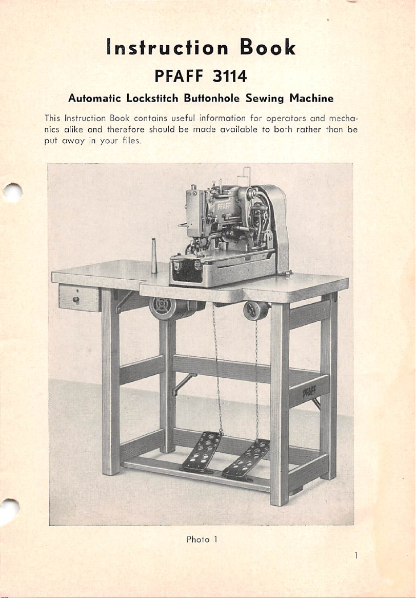
Instruction
Book
Automatic
This Instruction Book
nics
alike
and
therefore
put
av/ayinyour
PFAFF
Lockstitch
contains
should
files.
3114
Buttonhole
useful informoHon for
be
made
Sewing
available
operators
to
both
Machine
and
rather
mecha
than
be
Photo
1
Page 4
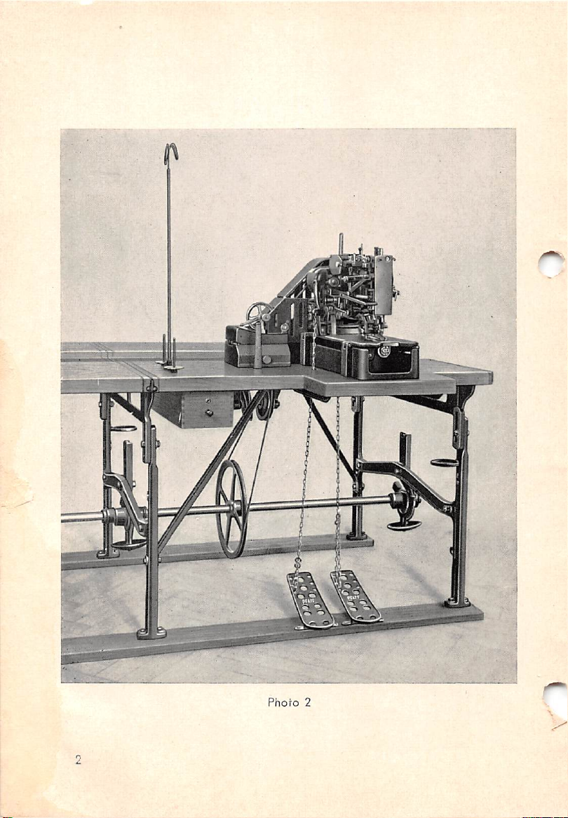
Photo
2
Page 5
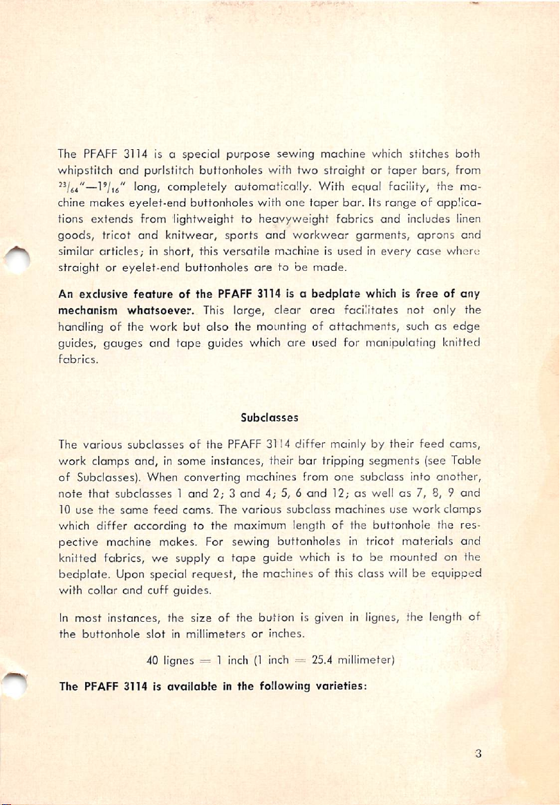
The PFAFF 3114 is a special
whipstitch
and
purlstitch
purpose
buttonholes
sewing
with
machine which stitches
two
straightortaper
bars,
both
from
—I'/ifi" long/ completely automatically. With equal facility, the ma
chine
makes
eyelet-end
tions
extends
goods,
similar
from lightweight to
tricot
and
articles;inshort,
straightoreyelet-end
An
exclusive
mechanism
featureofthe
whatsoever.
handling of the work but
guides,
fobrics.
The
work clamps
gauges
various
subclassesofthe
and,
of Subclasses). When converting machines from one subclass into
note
that
subclasses1and
10
use
the
same
which
differ
according to the maximum lengthofthe buttonhole tiie
pective machine mokes. For sewing buttonholes in tricot materials
buttonholes
knitwear,
this
sports
versatile
buttonholes
PFAFF 3114 Is a
This large, clear
also
the mounting of
and
tape
guides which
Subclasses
PFAFF 31!4
in some instances, their
2; 3
and
feed
cams.
The
various
with
one
taper
bar.
heavyweight
and
workwear
machineisusedInevery
are
to be
fabrics
garments,
made.
bedplate
area
facilitates not only the
attachments,
are
used for manipulating knitted
differ
mainlybytheir
bar
tripping segments (see Table
4; 5, 6
and
12;aswellas7, 8, 9
subclass
machines
Its
rangeofapplica
and
includes linen
aprons
case
which is
freeofany
such as
feed
use
work
and
where
edge
cams,
another,
and
clamps
res
and
knitted fabrics, we supply a tape guide which is to be mounted on the
bedplate. Upon special request, the machines of this class will be equipped
with collar
and
cuff guides.
In most instances, the size of the
the
buttonhole
slotinmillimeters
40 lignes = 1 inch(1inch 25.4 millimeter)
The PFAFF 3114 is
availableInthe
button
or
inches.
following
is given in lignes, the length
varieties:
of
Page 6
Lenghf
Buttonhole
'/4"-l"
Inside
of
Model
Dimensions
of
Feed
WIdfh
"/S4
-•'Ui
Work
Frame
Length
IVs.'
ClassofWork
Lingerie
Blouses
Corsetry
Stitch
with 2
Diagram
straight
bars
V/'-l"
"2"-lV4"
'//'-T/4"
V2"-l'/4'
Vs"
1"
^'4"-V
15/
'i/
^-1.
1"/
]19j
2"/,
1"/s
li
It*
]*9I
It*
l"/44"
Tricot
Knit
Goods
Ladies'
Wear
Sport
and
Work
Clothes
Extra
long
belt
and
slashes
flies
flaps
Clothing
Goods
button
slots
and
in
work
button
and
trouser
holes,
aprons
clothes
Ornamental
holesInlapels
sleeve
Buttonholesintrouser
front
pocket
Work
Staple
with2straight
with2straight
with 2
with2taper
with1taper
and
withttaper
and1conceoled
pear-shaped
with1straight
and
pear-shaped
l"/4
Work
Staple
Clothing
Goods
bars
bars
straight
bars
bar
bars
eye
and1conceoled
eye
bar
bar
V4"-l'/4"
1^744"
Work
Staple
Clothing
Goods
with1taper
and
and1concealed
pear-shaped
bar
eye
Page 7
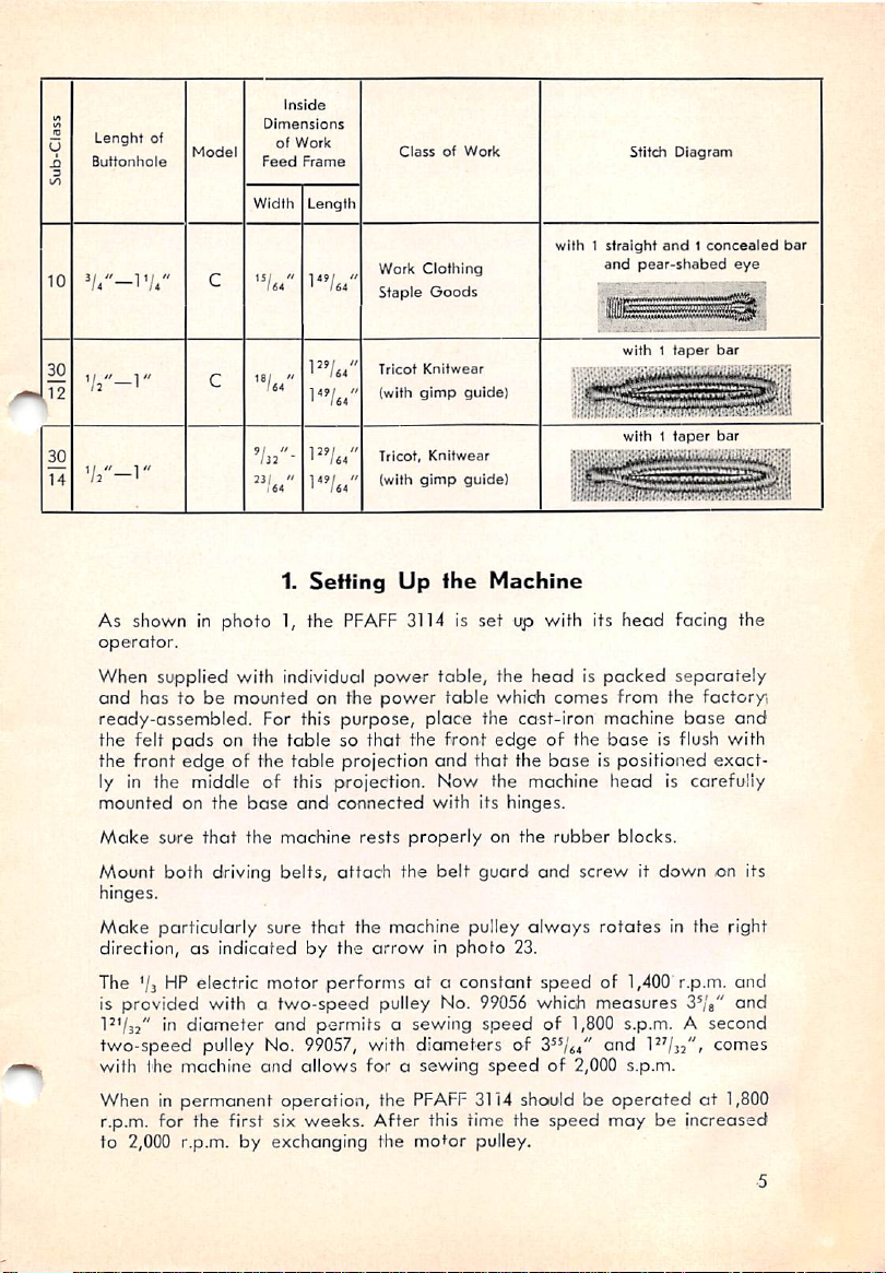
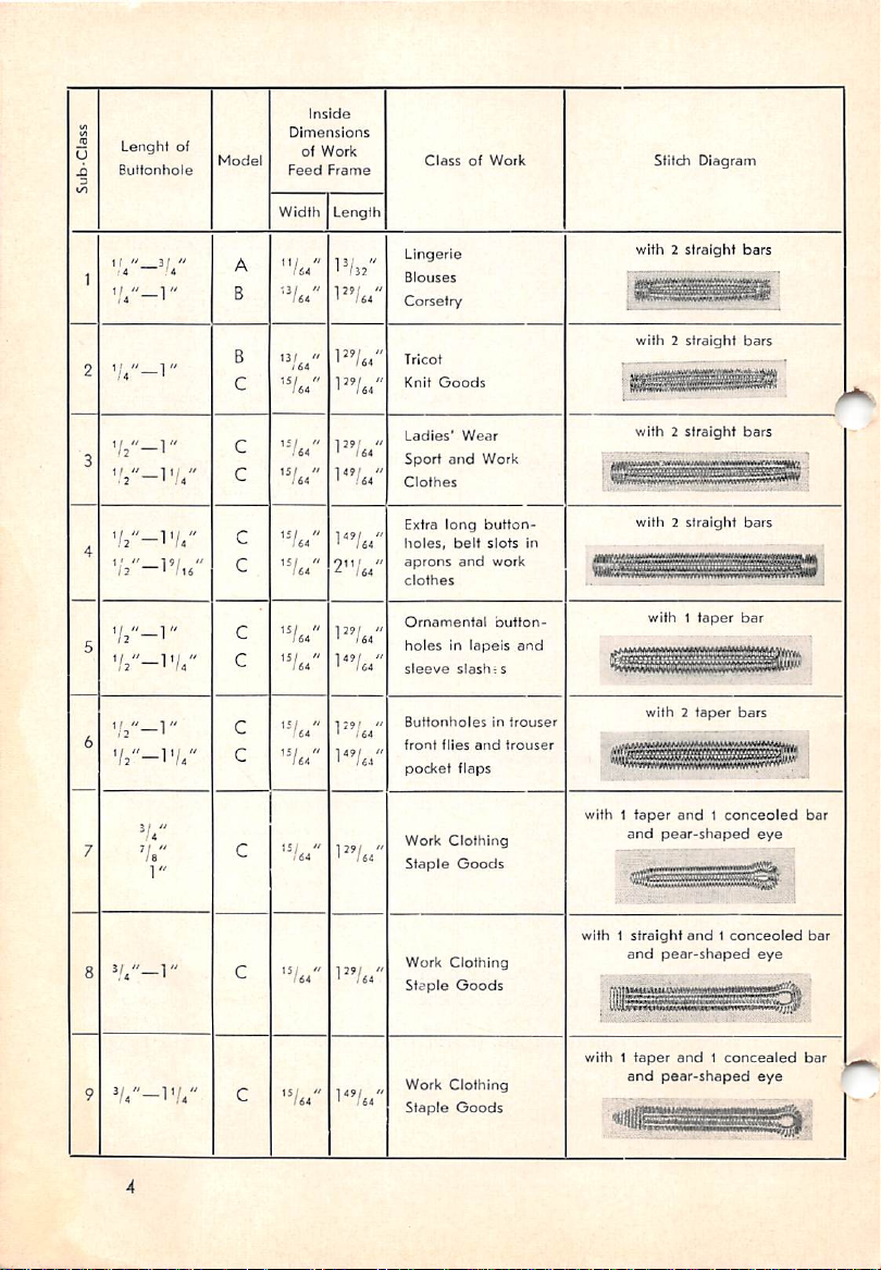
10
Lenght
Buttonhole
^/4"-T/4'
Inside
of
Model
Dimensions
of
Feed
Width
Work
Frame
Length
ClassofWork
Work
Clothing
Staple
Goods
with 1
Stitch
straight
and
Diagram
and1concealed
pear-shabed
bar
eye
Tricot
30
V/'-V
12
30
14
As shown in
operator.
When
and
ready-assembled.
the felt
the
front
732
l"/64
Jl/..
1''/S4
1.
Setting
photo
1, the
PFAFF
supplied with individual
has to be mounted on the
For this purpose,
pads
on the
of the
tablesothat
table
projection
edge
(with
Tricot,
(with
Up
3114 is
power
power
Knitwear
gimp
guide)
Knitwear
gimp
guide)
the
table,
table
place
the front
and
that
ly in the middle of this projection. Now the machine
mounted
Make
Mount
hinges.
Make
direction,asindicated
on the
base
sure
that
the machine
both
driving
particularly sure
and
belts,
by
connected
rests
properly
attach
that
the
the machine pulley
the
arrowinphoto
with its hinges.
belt
TheVaHP electric motor performsata constant
is provided with a
in
two-speed
diameter
pulley No. 99057, with
with the machine
When in
permanent
r.p.m. for the first six weeks.
two-speed
and
permitsasewing
and
allows
operation, the
pulley No. 99056 which
diameters
for a
sewing
PFAFF
After
3114 should be
this time the
to 2,000 r.p.m. by exchanging the mofor pulley.
with1taper
with 1
taper
bar
bar
Machine
set
up with its
the
headispacked
which comes from the factor/i
the cast-iron machine
edge
of the
the
baseispositioned
on the
rubber
guard
and
always
23.
speed
speedof1,800 s.p.m. A second
of ond P'/a:"* comes
speedof2,000 s.p.m.
speed
head
facing the
separately
base
base
is flush with
head
is carefully
blocks.
screwitdown
rotates
in the right
of 1,400 r.p.m.
measures
S^/g"
operatedat1,800
may
be increased
and
exact
on its
and
and
-5
Page 8
When using first-rate thread, the sewing
2,200 r.p.m. For this purpose, mqtor pulley No.
4^/32"
and
When ordering motor pulleys,
shaft.
In
those
cases
has to be used, a
set
up on individual
is avoi-lobleatextra
whereamotor
speed
reducer will be furnished for the
power
table. The
please
withahigher
should be specified on the order. High-speed motors
because
ratios.
the small pulleys
they
require
speed
may
cost.
specify the
speedisalready
typeofspeed
have
very
even be increased to
99058,
diameter
are
unfavorable
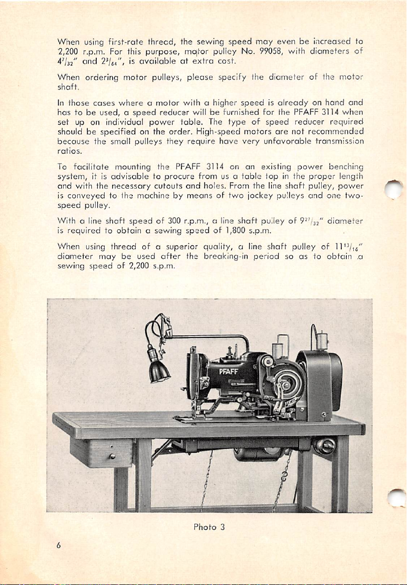
To facilitote mounting the PFAFF 3114 on an existing
system,
and with the
is
speed
With a line
is
When
diameter
sewing
it is
advisabletoprocure
conveyedtoihe
necessary
pulley.
shaft
cutouts
machinebymeansoftwo
speedof300 r.p.m., a line
requiredtoobtainasewing
using
thread
may
speedof2,200 s.p.m.
ofasuperior
be
used
after
from us a
and
holes. From the line
table
jockey
shaft
pulleyof9^'/32"
speedof1,800 s.p.m.
quality,
the breaking-in
a line
period
fop in the
pulleys
shaft
with diameters
of the motor
on
PFAFF
reducer
hand
3114 when
required
not recommended
transmission
power
shaft
pulley
so
astoobtain
proper
pulley,
and
of
benching
length
power
one
diameter
11
of
end
two-
,a
Photo
3
Page 9
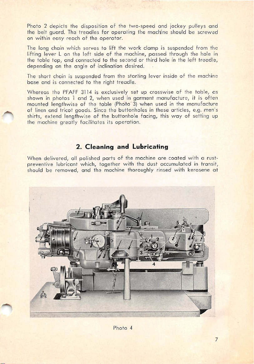
Photo2depicts
the belt guard. The
on within
The long chain which
lifting lever L on the
the
toble
depending
the
dispositionofthe
easy
treadles
reachofthe
top,
on the angleofinclination
left
and
connectedtothe
for
operator.
serves
to lift the
sideofthe machine,
two-speed
operating
work
second
desired.
and
jockey
pu'Ileys
the macNine should be
clampissuspended
passed
or third hole in the
through the
left
and
screwed
from
hole
treadle,
the
The short chain is suspended from the starting lever inside of the machine
base
endisconnectedtothe
Whereas
shown in
mounted
the
PFAFF 3114 is
photos1and2,when
lengthwise of the
right
treadle.
exclusively
usedingarment
toble
(Photo 3)
setupcrosswiseofthe
when
manufacture,
used
in the
table,
it is
manufacture
as
often
of linen and tricot goods. Since the buttonholes in these articles, e.g. men's
shirts,
extend
the machine
When
delivered,
prevenlive
should be
lengthwise of the buttonhole facing, this
greatly
lubricant which,
removed,
facilitates
2.
all
polished
its
operotion.
Cleaning
and
the machine thoroughly rinsed with
and
Lubricating
partsofthe machine
together
with the
are
dust
way
of setting up
coated
accumulated
with a rust-
in transit,
kerosene
ir>
ot
Photo
4
Page 10
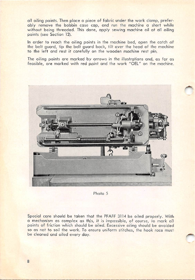
all oiling points. Then
ably
remove
without
being
the bobbin
threaded.
points (see Section 12).
In
ordertoreach
the
belt
to the
guord,
left
The oiling
feasible,
are
points
and
marked
the
tip the
rest
ore
place
a piece of fabric under the work clamp,
cose
cap,
and
This
done,
oiling
pointsinthe
belt
guard
back,
it carefully on the
markedbyarrows
with
red
pqint
UlUUIBBSf
run the machine a short while
apply
sewing machine oilatall oiling
machine
tilt
wooden
over
bed,
the
machine
in the illustrations
and
the
work
open
the
headofthe
rest
pfini.
and,asfar
"OEL"onthe
prefer
catch
machine
machine.
o;f
as
Photo
5
Special
a mechanismascomplexasth,is, it is impossible,ofcourse,tomark
care
should be taken
that
the
PFAFF
3114 be oiled properly. With
all
points of friction which should be oiled. Excessive oiling should be avoided
soasnottosoil
be
cleaned
and
the
work.Toensure
oiled
every
day.
uniform
stitches,
the
hook
race
must
Page 11
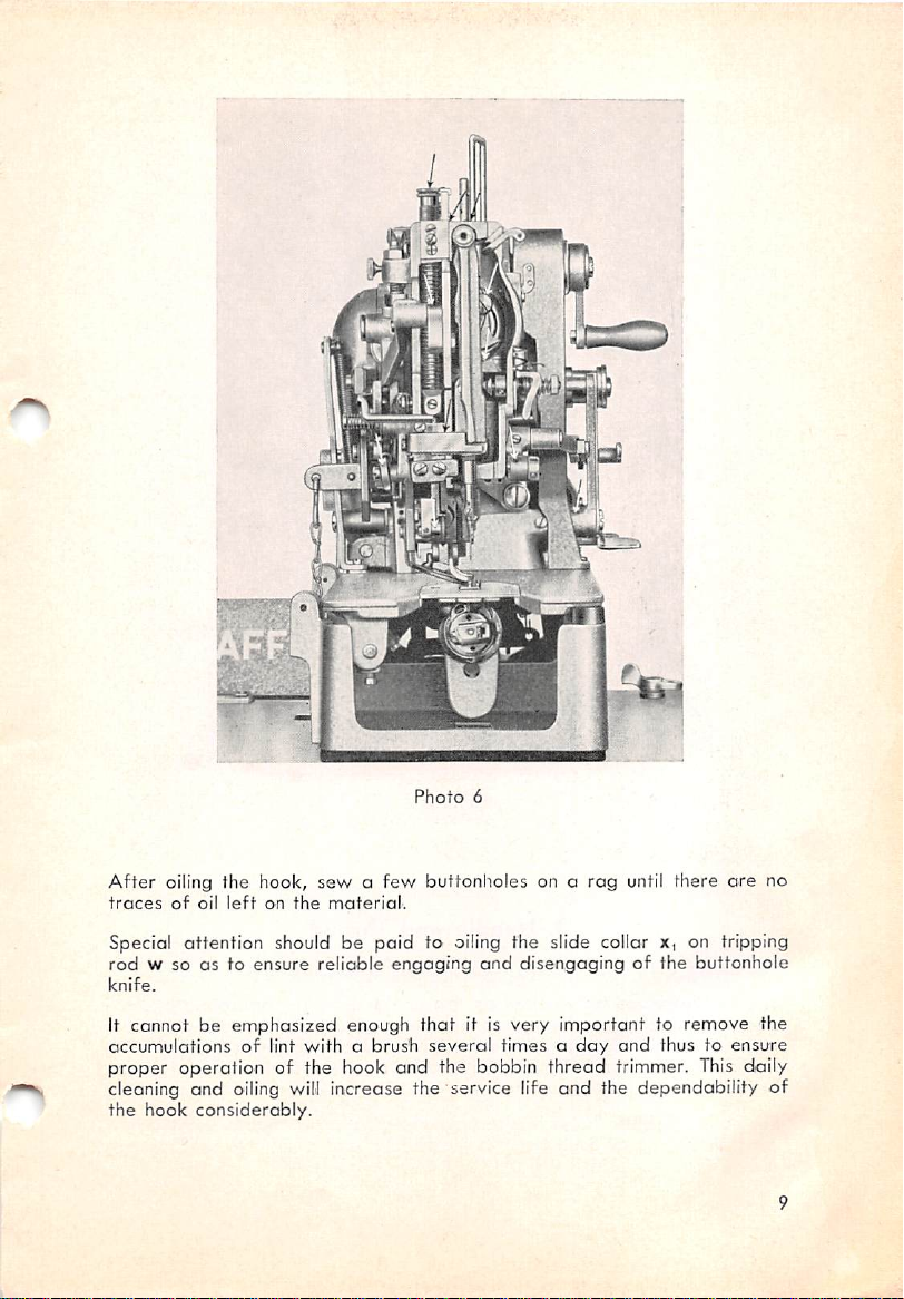
After
oiling the hook,
traces
of
oil
•.V"t
left
on
sewafew
the
material.
n
Photo
6
butfonlioles on a
rag
until there
are
no
Special attention should be
paid
to oiling the slide collar x, on tripping
rod w so as to ensure reliable engaging and disengaging of the buttonhole
knife.
It cannot be emphasized enough
accumulationsoflint
withabrush
that
it is very important to remove the
several
timesaday
and
thus to
ensure
proper operation of the hook and the bobbin thread trimmer. This daily
and
cleoning and oiling witl increase the service life
the
hook
considerably.
the dependability of
Page 12
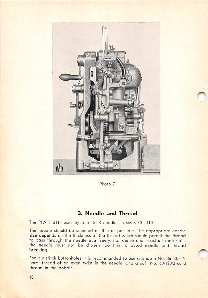
Phot-o
7
3.
The PFAFF 3114
uses
Needle
System
and
134R
neediesinsizes
Thread
70—110.
The needle should be selected as thin as possible. The appropriate needle
size
to
the
depends
pass
needle
on the thickness of the
through the
must
not
needle
be
eye
chosen
thread
freely. For
too
thin
which should permit the
dense
and
to
resistant
avoid
needle
materials,
and
thread
thread
breaking.
For purlstitch buttonholes it is recommended to use a smooth No. 36-50/4-6-
cord,
thread
10
threadofan
in
the
bobbin.
even
twistinthe
needle,
andosoft
No.
60-120'3-cord
Page 13
'Whipstitch
thread.
be
usedinthe
We
weights
the
Besides the quality of the
should be given due consideration
may
for
too
typeofwork.
The
weights most suitoble for the purpose the machine is intended for.
No
guarantee
the
neat
ofopoor
If
thereisany
to find
treadle
buttonholes
For
best
results, o
needle.
should like to
turn brittle
PFAFF 3114 is corefully stitched
recommended
end
long. Inferior
will be
appearance
qualityisused.
doubt
out
whether
halfway
call for the
soft
thread
stressatttvis
loose
quality
assumed
as well as the durability of the buttonhole if
about
the
down
threadorthe
and
4.
point
above
thread
it is its conditionatthe time of use whrch
their tensile
threads
for the
the
causeofthread
sew
the
Inserting
some
weightofneedle
oF an
even
and
that
strength
are
off
proper
with
only the very
for sewing buttonholes.
even
threads
when
completely
threads
working of the machine
shouldbeused
because
breaking
machineisat
buttonholeathalf the
the
Needle
moderate
storedindry
and
twist
best
threads
of superior quality
unsuitable for this
of the
grades
and
fault,
press
normal
you
the
bobbin
should
in
rooms
and
end
thread
want
right
speed.
The needle. System 134R, is linserted inio the needle
bar
with the long
groove facing the arm standard, and is pushed up as far as it will go.
5.
As shown in
the
thread
Threading
photc»s
from the threod unwinder through the hole in spool pin 1,
4 and 8, the
PFAFF
the
Needle
3114
Js threaded as follows: Pass
be
tween the discs of top tension 2, at the beck of threod pull-off pin 3,
through
thread guide 4 and the upper hole of thread guide 5, between the
discs of main tension 6, through thread check spring 7, under thread regula
tor 8,
through
thread guide9 and take-up lever
10,
through
thread guides
12 and 13 on top and bottom of the face plote and on the needle bar, ond
back-front through the needle
eye
14.
After threading the needle and before commencing to sew the first button
hole, lay the needle thread toward you
bobbin
thread
with your
hand
under the
under
the work clamp and hold the
needle
plate.
11,
11
Page 14
a
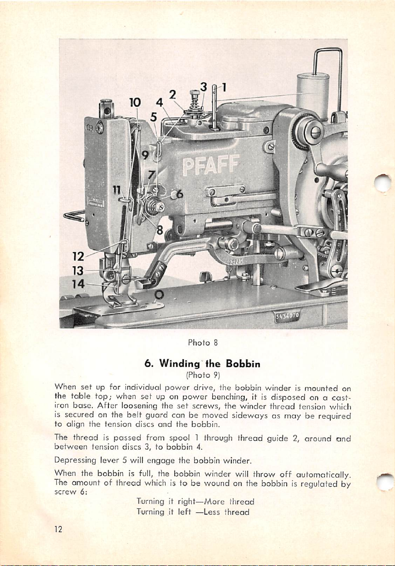
Phofo
8
6.
Winding
When
set
the table top; when set up on power benching, it is disposed on c cast-
up for individual
iron
base.
After
loosening the
is secured on the belt guard can be moved sideways as may be required
to
align
the
tension
The thread is
between
Depressing lever 5 will
When
The
screw
tension
the bobbin is
amount
of thread
6:
discs
passed
discs3,to
power
and
from spool 1 through thread guide 2, oround
bobbin
engage
full,
the bobbin winder
which
is to be
Turning it right—More
Turning it
fhe
Bobbin
(Photo
9)
drive, the bobbin winder is mounted on
set
screws,
the
bobbin.
the bobbin winder.
left
4.
wound
—Less
the
winder
will
on the
thread
thread
thread
throw off automatically.
bobbin
tension which
is regulated by
and
12
Page 15
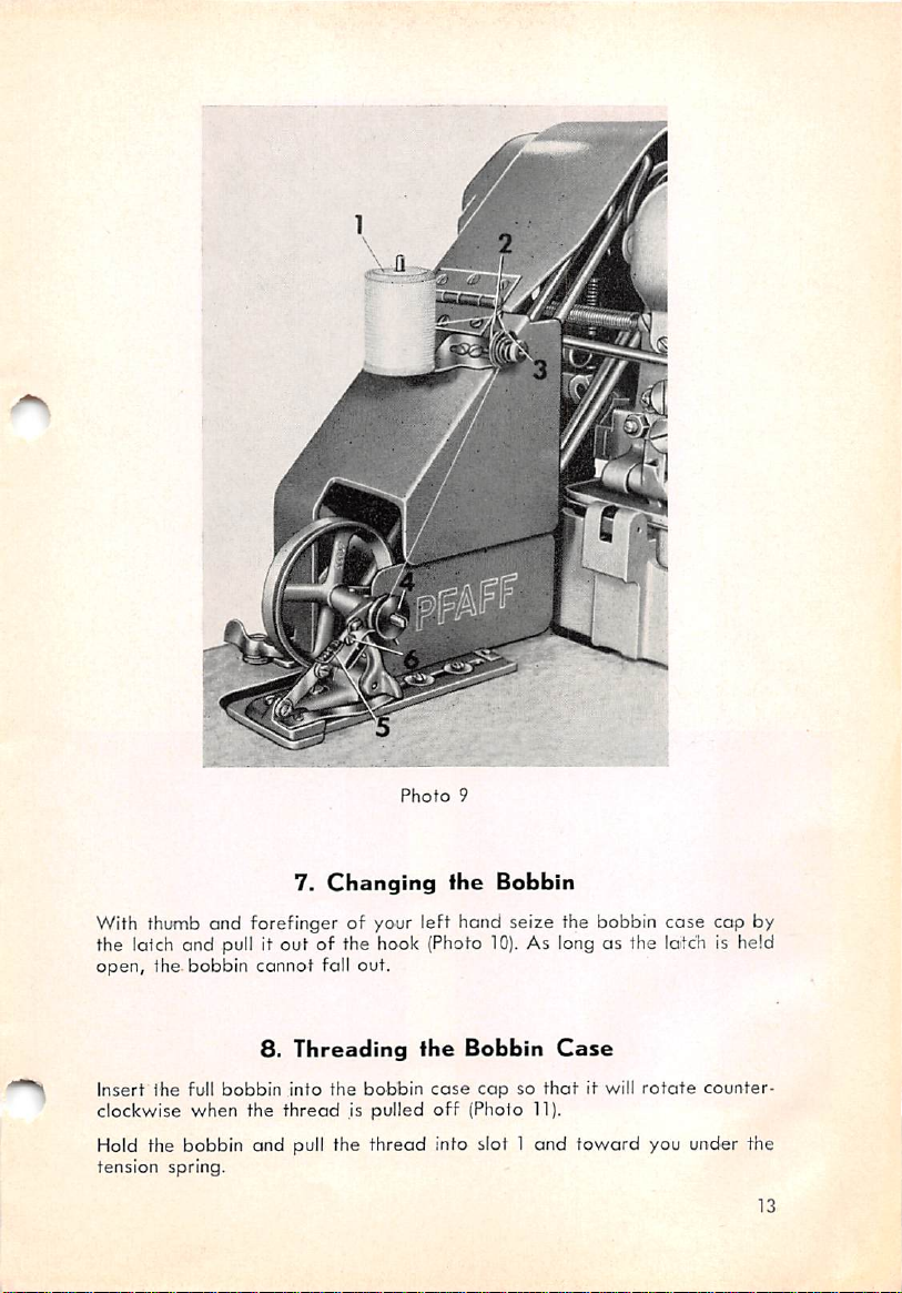
7.
Changing
Photo
9
the
Bobbin
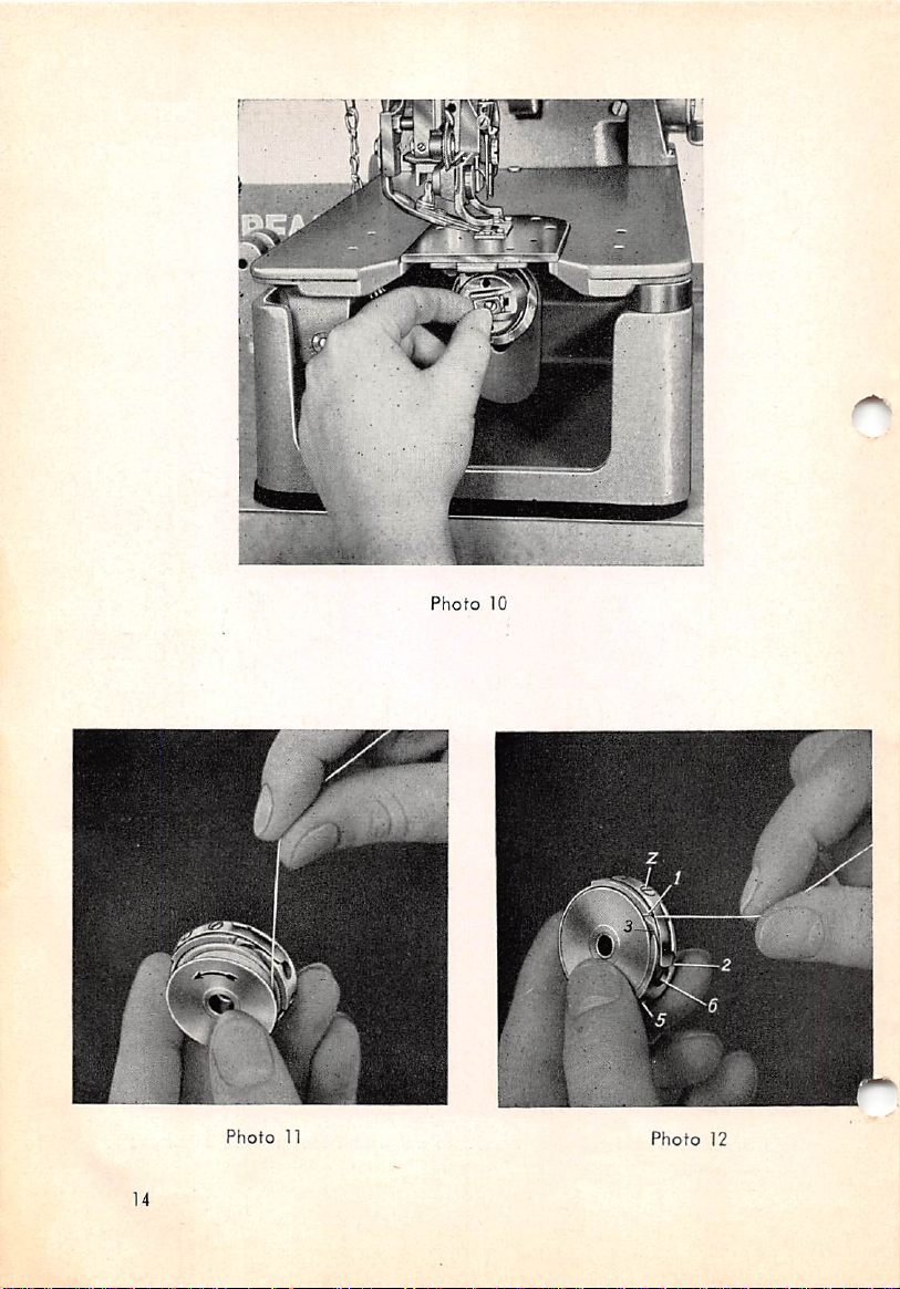
With thumb and forefinger of your left hand seize the bobbin
10).
the latch and pull it out of the hook (Photo
As long as the lotch is held
open, the. bobbin cannot fall out.
8.
Threading
Insert
the
full
clockwise
bobbin
when
Hold the bobbin and pull the
tension
spring.
the
into
thread
the
,is
bobbin
pulled
thread
the
Bobbin
case
off
(Pholo 11).
info slot 1
Case
capsothat
and
it will
toward
case
cap by
rotate
counter
you under the
13
Page 16
Photo
10
Photo
11
14
Photo
12
Page 17

Then
retain
the
forefinger of
through the
4
into
the
When letting go of the
threadinfront
yo-ur
gap
delivery
left hand until the thread is pulled back into slot 3,
between the bobbin case and the bobbin, and through slot
eye
5.
thread
will properly snap under the tension spring and be visible through
ture6(Photo
4).
While holding the latch open, the bobbin
ed
onto
the
center
studinthe
of the tipofthe tension spring with the
and
pulling it through the delivery
case
cap
and
bobbin
case
base
and
the bobbin
the
latchisclosed.
ore
eye,
aper
push
A slight pressure exerted with the thumb will make the cap snap into posi
tion audibly. This is very important since an improperly inserted bobbin icase
may cause
damage
to the hook, the bobbin
case
or the needle.
it
Photo
Photo
13
14
9. Regulating the Bobbin Thread Tension
The bobbin thread tension is regulated by means of screw z (Photo
Tightening
decrease
this
screw
will
it.
increase
the
tension,-
and
looseningitwi-Ii
Purlstitch buttonholes of any description require a very weak bobbin thread
tension.
The
tension
by its own weight when letting it hang on the threod.
account
is properly regulated if the bobbin case
should the
bobbin
thread
tension be
will
slowly
(Photo
increasedinexcess
15).
slide down
16).
On no
of
the
15
Page 18

Photo
15
Photo
16
amount given above since this would necessitate increasing the needle
thread
tension
The
PFAFF
when the machine is inoperative.
When
startingthe
It is set for a
tobelocked
and
10.
Regulating
3114
normal
insideofthe
m.ight
resultinthread breaking.
has
two
needle
machine,
amountoftension
material.
the
the top
Needle
thread
tension
Thread
tensions which
Sp 1
(Photo
and causes the
Tension
are
both
17)
is engaged
knotting
released
first.
stitches,-
After some stitches, the lateral tension Sp 2 is engaged and increases the
needle thread tension so that the bobbin thread
threads
purl-line
To
will
interlace on the top surface of the
along
either
parallelofthe buttonhole.
prevent breaking of the needle threaa, the tension Sp 2
willbepulled
fabric
and
up and both
form
a straight
should
not be
set tighter than is absolutely necessary for obtaining a raised seam coti-
struction without risking thread breaking.
16
Page 19

Sp
Phofo
17
For
best
It cannot be emphasized enough
results, cotton No.
that
so
the high sewing
Toprevent ravellingof the buttonhole, tension Sp 2 is automatically released
when making the last
the
threads
to
formadurable
Sp 1 is released when the machine has stopped.
36-50/4
speed
of the
two
or three stitches
concatenation
or 6-cord is used as needle threod.
that
only first-class thread should be .used
PFAFF
3114 can fully be utilized.
and
tension Sp 1 will cause
insideofthe
fabric.
Tension
To
ensure
that
the
needle
thread
will be pulled into the
tension Sp 1 is released by means of lever A (Photo
is
cut
open.
In
case
sewn
inferior quality
on the PFAFF 3114. For this
Sp 2 so
that
only tension Sp 1 will remain active.
thread
is used, only whipstitch buttonholes can be
purpose,
loosen
material
18)
while the buttonhole
the
thumb nutoftension
securely,
17
Page 20

11.
1
Placement
Photo
18
ol
the
Work
When depressing the left
is
placed
under the needle. In
into
the
machine
order
treadle,
the work clamp is raised. Then the work
with
the
front
to ovoid crooked buttonholes, the buttonhole
endofthe
marked
buttonhole
marking should be placed exactly in the middle under the work clamp.
When the left treadle is released, the work clamp is again lowered onto
the
work.
Upon lifting the work clamp, lifting lever L is pulled between the vertical
guide
and
the
lower
started
accidentally while the work clamp is
endoflocking lever S so
12.
Slariing
ihe
that
raised
Machine
the machine
(Photo 18).
cannot
be
Don't run the machine unless you have thoroughly familiarized yourself with
its operation. Make particularly sure that you know how to stop the mo-
chine
during
mechanism (see Section
18
o sewing
cycle
and practise actuating the
14).
Only when the operator is fully acquainted with
knife
interlocking
Page 21

these
manipulations
know
the machine is to turn the machine pulley by
can
she
commence
sewing. The
best
hand
waytoget
andtostudy
all
phases of the performance of the machine. Then, preferably without
threading the machine
motor
and
run
the
and
machine,
with the bobbin
but
don't
let
the
case
removed, switch on the
knife
cut.
to
By pressing down the right
driving
driving pulley, thus driving the machineathalf
right treadle all the
the
the
stage,
lever S
accidentally while sewing (Photo 18).
The
belt
(low
speed)isshifted
way
rear
driving belt (high speed) is shifted from the
rear
driving pulley, thus bringing
the front driving
arrests
two-belt
lifting lever L so
drive
ensures
not only faster but also at a lesser
slippage and excessive
13.
treadle,
the
brakeisreleased
from the
front
loose pulley to the
speed.
and
the front
When pressing the
down (and then taking the foot off the treadile),
rear
loose pulley to
speed.
At this
and
locking
raised
to
top
speed
belt
is shifted to the
that
wear
are
Stopping
the
machinetofull
rear
that
the work clamp cannot be
the
machiiieisaccelerated
power
greatly
eliminated.
the
loose pulley,
consumption and that
Machine
front
belt
After completion of the buttonhole the machine stops automatically. Shortly
before making the bartacking stitches, the machine is automatically slowed
down to half speed in order to effect a soft impact of the buttonhole knife.
the
advantage
machine
Another
of
buffer springs when the machine stops instantaneously.
eliminate the
of this reduction in speed is the fact that the momentum
is much
less
and
can
be
easily
absorbed
by
This
breakageofparts
and
trouble in the machine.
the
will
double
greatly
14.
Stopping
Instant stopping of the
Important when thread jams
the
machine
in
Machine
during
While
Sewing
the sewing cycle is particularly
the hook race or the needle breaks
ios,
otherwise, the fabric or the hook would be damaged by fragments of the
needle or its
would be easily
stump.
damaged
This
is especially essential with delicate fabrics
by punctures of the needle stub.
which
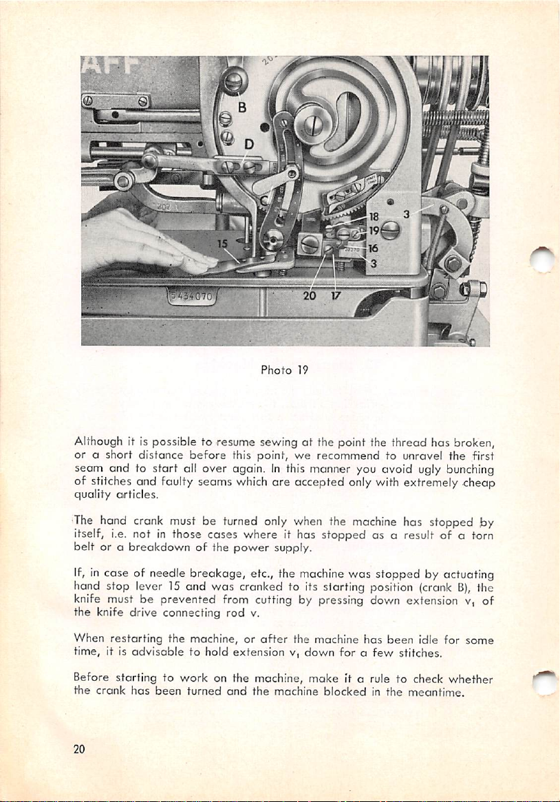
The machine is stopped by quickly pressing down hand stop lever 15 twice
(Photo
19).
case
the
In
bobbin
runs
outofthread
or
the
thread
breaks
while
sewing
the buttonhole, it is possible to let the machine complete the needle cycle
until it is in starting position again. However, the cutting of the knife
the close of the needle cycle must be
prevented
in any case.
at
19
Page 22
Photo
19
Although it is possible to resume sewing at the point the thread has broken,
or a short distance
before
this point,
we
recommend to unravel the first
seem and to start all over again.Inthis manner you avoid ugly bunching
of stitches and faulty seams which are accepted only with extremely cheap
quality
•The
articles.
hand crank must be turned only when the
machine
has stopped by
itself, i.e. not in those cases where it has stopped as a resultofa torn
belt
or a
breakdown
of the
power
supply.
If, in cose of needle breakage, etc., the machine was stopped by actuating
hand stop lever 15 and was cranked to Its sfarting position (crank
B),
the
knife must be prevented from cutting by pressing down extension v, of
the knife drive connecting rod v.
When
restarting
time, it is
the machine, or
advisable
to hold
after
extensionv,down
the machine
for a
has
few
been
stitches.
idle for
some
Before storting to
the
crank
has
been
20
work
on the machine,
turned
and
the
machine
make
It a rule to check
blockedinthe
whether
meantime.
Page 23

Photo
Photo
20
21
Blocking of the machine
the
crank
was
of
connecting
lever Hj by
turned which
rodvnot
set
collar x (Photo 28).
may
occur when it did not
caused
being
the knife to cut
locked, it is
pressed
stop
automatically
prematurely.
against
and
As a
result
knife driving
21
Page 24

15.
Regulating
the
Length
of
Buttonhole
To regulate the length of the buttonhole, loosen locking lever C (Photo 21)
and
move
feed
required.
creases;
When
when
driving
moving
moving it
rod
D in the slot of
rod
D up, lengthwise
down,
the lengthofbuttonhole
feed
regulatorEas
travelofthe
may
work
clamp
decreases.
be,
in
To facilitate this setting, feed regulator E is provided with a graduatfon
whose
numbers Indicate the length of the cut in inches
buttonhole knives
are
marked occordingly.
and
millimeters. The
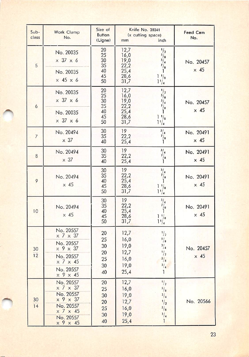
The length of buttonhole (length of buttonhole knife blade) in relation to
the
sizeofthe
Sub
class
Work
No.
button
usedisshowninthe
Clamp
Size
Button
(Ligne)
table
below:
of
mm
(x
Knife
cutting
No.
20241
space)
incti
Feed
Cam
No.
10
No.
20401
X28 X
1
2
3
4
4,5
No.
20035
X37X 5
No.
20035
X37X 5
No.
20035
X37X 6
No.
20035
X37X 6
No.
20035
X45X 6
No.
20035
X45X 6
No.
20035
X55X 6
15
20
25
30
35
40
10
15
20
25
30
35
40
20
25
30
35
40
45
50
35
40
45
50
55
60
62
6,4
9,6
12,7
V«
Va
1/2
16,0 V,
19,0 V-
22,2 Va
25,4 1
6,4
9,6
12,7 V:
Va
Va
16,0
19,0 ^4
22,2 '/e
25,4 1
12,7
V2
16.0
19,0
22,2 7a
25,4 1
28.6 1
Va
31.7 IV,
22,2
25,4 1
28.6 1
Va
Va
31.7 IV.
35.0 1 Va
38.1 1 Vi
39,7 1 V.a
No.
No.
No.
No.
20226
X
20226
X
20226
X
20226
X
40
40
53
53
22
Page 25
Sub
class
Size
Work
Clamp
No.
No.
20035
5
6
7
8
9
10
30
12
30
14
X37X 6
No.
20035
X45X 6
No.
20035
X37X 6
No.
20035
X37X 6
No.
20494
X
37
No.
20494
X 37
No.
20494
X
45
No.
20494
X
45
No.
20557
X 7 X
No.
20557
X 9 X
No.
20557
X 7 X
No.
20557
X 9 X
No.
20557
X 7 X
No.
20557
X 9 X 37
No.
20557
X 7 X
37
37
45
45
37
45
N^20557
X 9 X
45
of
Button
(Ligne)
20
25
30
35
40
45
50
20
25
30
35
40
45
50
30
35
40
30
35
40
30
35
40
45
50
30
35
40
45
50
20
25
30
20
25
30
40
20
25
30
20
25
30
40
Knife
No.
(x cutting
mm
2024t
space]
Indi
12,7 V:
16,0
19,0
22,2
25,4 1
28.6 1
5/8
5/8
'/.
Vb
31.7 VU
12,7
'/,
16,0 5/
19,0 5/
22,2
25,4
^/8
28.6 1
31.7 IV.
19
V4
22,2 V,
25,4 1
19 V.
22,2
25,4 1
19 V.
22,2
25,4 1
Vb
28.6 1
31.7 IV.
19 V.
22,2
25,4 1
28.6 1
31.7 IV.
12,7 %
16,0
19,0 V.
12,7 V:
16,0 V.
19,0 V.
25,4
12,7 V,
16,0
19,0 V.
12,7
16,0
19,0 V.
25,4 1
1
Ve
Vb
Vb
Vb
Vb
Vb
Va
Feed
Cam
No.
No.
20457
X
45
No.
20457
45
X
No.
20491
X
45
No.
20491
X
45
No.
20491
X
45
No.
20491
X
45
No.
20457
X
45
1
No.
20566
23
Page 26
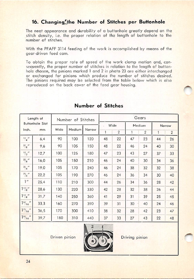
16. Changingf^the
The
neat
stitch density, i.e. the
number
With
gear-driven
To
sequently, the
hole chosen, the pinions
or
The pinions
reproduced
appearance
of
stitches.
the
PFAFF 3114
obtain
the
exchanged
feed
cam.
proper
proper
for pinions which
required
on the
back
Number
and
durability of a buttonhole
proper
feedingofthe
rateofspeed
number of
marked1and
ol
relation of the length of buttonhole to 'the
workisaccomplishedbymeansofthe
of tlie
stitches
2 in
produce
maybeselected
cover
of the
from the
feed
Stifches
work
per
greatly
clamp
Buttonhole
depend
motion
in relation to the length of
photo23are
the
number
table
gear
housing.
either
of stitches
below
which is
interchanged
on the
and,
button
desired.
con
also
Inch.
V'/'
'/?"
Vs"
V/'
Vb"
1"
1'/^"
1'//'
IV,b"
1'/ib"
IV,b"
Length
ot
mm
6.4
9,6
12,7
16,0
19,0
22,2
25.4
28,6
31,7
33,3
36.5
39,7
Number
Wide
Medium
90
90
100
105
105
105
110
130
140
160
170
180
Driven pinion
Number
of
100
105
125
150
170
190
210
220
250
270
300
310
Stitches
Narrow
120
150
180
210
240
270
300
330
360
390
410
440
If
of
Sfitches
1
48
48
47
46
46
46
44
42
41
39
38
37 33
J
Gears
Medium
2 1 2
22
47
22
46
23
43
24
40
24
38
24
36
34
26
32
28
29
31
31
30
-
32
28
27
Driving pinion
Narrow
2
1
23
44
26
24
40
30
27
37
33
30
34
36
32
32
38
34
30
40
36
28
42
38
26
44
39
25
45
40
24
46
42
23
47
22
43
48
24
Page 27

The number of teeth given in any two of the adjoining columns must
up to 70. The driving
the
operator
(Photo 23).
pinion
No. 1 should be mounted on the stud close to
add
After swinging up the cover, the pinions can be easily pulled
and
interchangeable
holds the
feed
feed
gears
geors in position on their studs should be
mounted without tools. The cover which
off
kept
the studs
closed while
sewing so that the pinions cannot fall out.
17.
Changing
The stitch
regulatedatlever H (Photo
width
for the
ihe
Widfh of
bartocking
22).
The upper thumb screw J serves to regulate
and
Bar
and
buttonhole
Parallel
stitches (parallels) is
the width of bight for the buttonhole parallel, and the lower thumb screw K
for
the
bar.
Turn
them
Turn them
inwardly
outwardly
for
wider
for
stitch
norrower
width
stitch
width
\
N,^.WVf
Photo
j'
22
25
Page 28

18.
Adjusting
The position of the buttonhole in relation to the cutting space is adjusted
as
follows:
The
zero
vibrates
When the amount of needle vibration is reduced to zero by turning screw J
out, i.e. when the needle
either parallel of the buttonhole on its right.
The knife must cut the slash exactly in the middle of the buttonhole.
In
the knife is bent. If not, the position of the parollels must be corrected.
This
line of the needle
from
case
the cut is
is done by means of screw N and N, on lever M (Photo
right to
somewhat
the
Position
to
left
olways.
does
of
the
Buttonhole
the
Cutting
bar
vibration lies on the right, i.e. the needlef
not
off
center,
Space
vibrateatall, the needle
first check
whether
in
the
22).Byturning
Relation
penetrates
needle
or
the lower screw N inwardly, the right parallel is moved to the left; by
turning it outwardly, to the right. Turninginwardly the upper screw N, wili
move the left parallel to the left; turning it outwardly, to the right.
19.
Regulating
fhe
Distance
(Photo
22)
Between
Parallels
As follows from the preceding section, the distance between the parallels
of the buttonhole can be regulated by means of screws N and N,. After
the regulation tighten the nuts of both screws x securely.
The distance
resultinan
When
inserting
the knife up in the knife holder as far as it
When
cutting
between
ugly
20.
a new
the fabric, the
the poralleis must not be
appearance of the buttonhole after
Exchanging
buttonhole
knife
the
knife,
should
Buttonhole
loosen
too
screw b
will
go.
descend far
wideasthis would
cutting
open.
Knife
(Photo
17)
end
enough
so that its
push
lowest point (front edge) is .04" below the needle plate. If the knife is
worn by grinding, it must be
26
set
lower accordingly.
Page 29

I
Photo
23
21.
Proper
The
knife
holderissetinsuchamonner
between
hole, and
If, in spite of the above, the knife should injure a bar, the knife holder must
be adjusted
the knife
that
the buttonhole will be cut open all the
after
loosening set screws c and d (Photo
and
Position
the
needle
ol
Knife
that
irregardlessofthe lengthofbutton
there
Holder
willbea
way
clearance
to the bars.
17).
of
22.
The
Needle
When depressing the left treadle after
Thread
finishing
Trimmer
the buttonhole, the needle
thread Is automatically trapped by the trapper spring, which is mounted
on the needle
hole
before
thread
the
trimmer,
work
clampisraised.
and
is cut on the top surface of the button
When re-starting the machine for the next buttonhole, the needle thread
trimmer
stitch
firstismoved
across
the
loose
back
and
endofthread.
thentothe
leftsothat
the
needle
can
After tacking the end, both the trimmer and the trapper spring open and
release
parallel of the next buttonhole.
the
thread
so
thatitmay
be completely covered by the first
27
Page 30
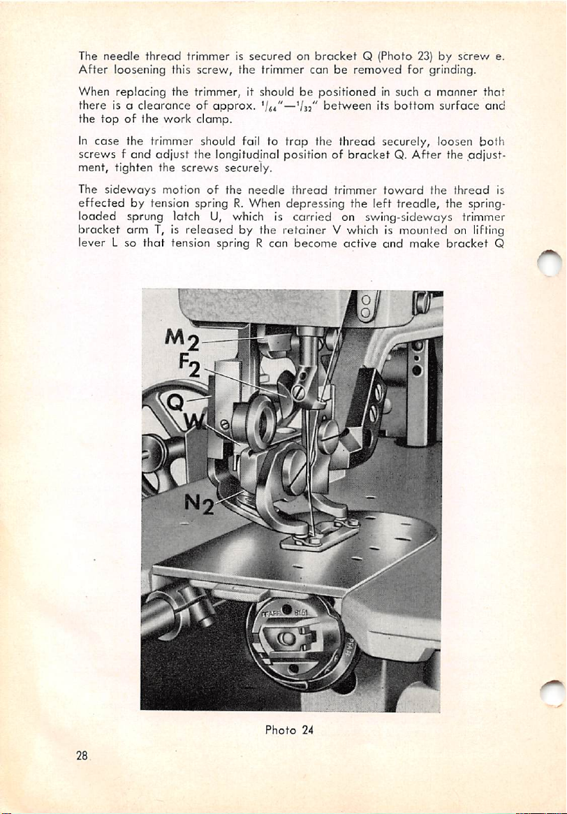
The
needle
After
When replacing the trimmer, it should be
there
the
top
case
In
screwsfand
thread
loosening this
is a
clearanceofapprox.
of the
the trimmer should fail to
trimmerissecuredonbrocketQ(Photo
screw,
work
clomp.
adjust
the longitudinal position of
the trimmer conberemoved
'lit
—'/jz
trap
positioned
between
the
in such o
its
thread
securely, loosen
bracketQ.After
23)byscrew
for grinding.
bottom
manner
surface
that
and
both
the .adjust
ment, tighten the screws securely.
The
sideways
effected
motionofthe
needle
thread
trimmer
by tension spring R. When depressing the left
toward
treadle,
the
thread
the spring-
loaded sprung latch U, which is carried on swing-sideways trimmer
bracket
lever L so
arm
T, is
that
released
tension spring R can
by the retainer V which is mounted on lifting
become
active
and
make
bracket
e.
is
Q
Photo
24
28
Page 31
and
the
trimmer
vertical
trimmer
the
cam
strikes
trimmer
When re-storting the machine, the trimmer
pushed sufficiently
guide W, so
Sprung latch U which yields
Vj"
below
Retainer V must be
between
sprung latch U
adjustmentisrequired,
N2 (Photo
the
closes
that
the
top
snap
back
and
far
forword
24}
sideWof
the
over
toward
on the
threadistrapped
movable
cam
to the left by the
the sprung lotch U will
downwardly
surface
set
of the
in such a
and
loosen
retainerbyangle
way
retainer
that
V when the trimmer is
set
screwOiand
the
needle
bladeofthe
guide
and
bracket
again
thread.
Thereby
needle
W, (Photo 23). As a
cut.
Q is pulled
slanted
be caught by
side
of
retainer
should be held in position
X (Photo 23).
there will be a
clearanceof.04"
retracted.
move
the
retainerVas
thread
result,
back
the .cam
about
the
ond
mayberequired.
To avoid
early, guide screw Fj (Photo 24)of
andisdisposed
bar
striking
Mj will
the
damage
force
trimmer.
to the needle
in such a
the trimmer
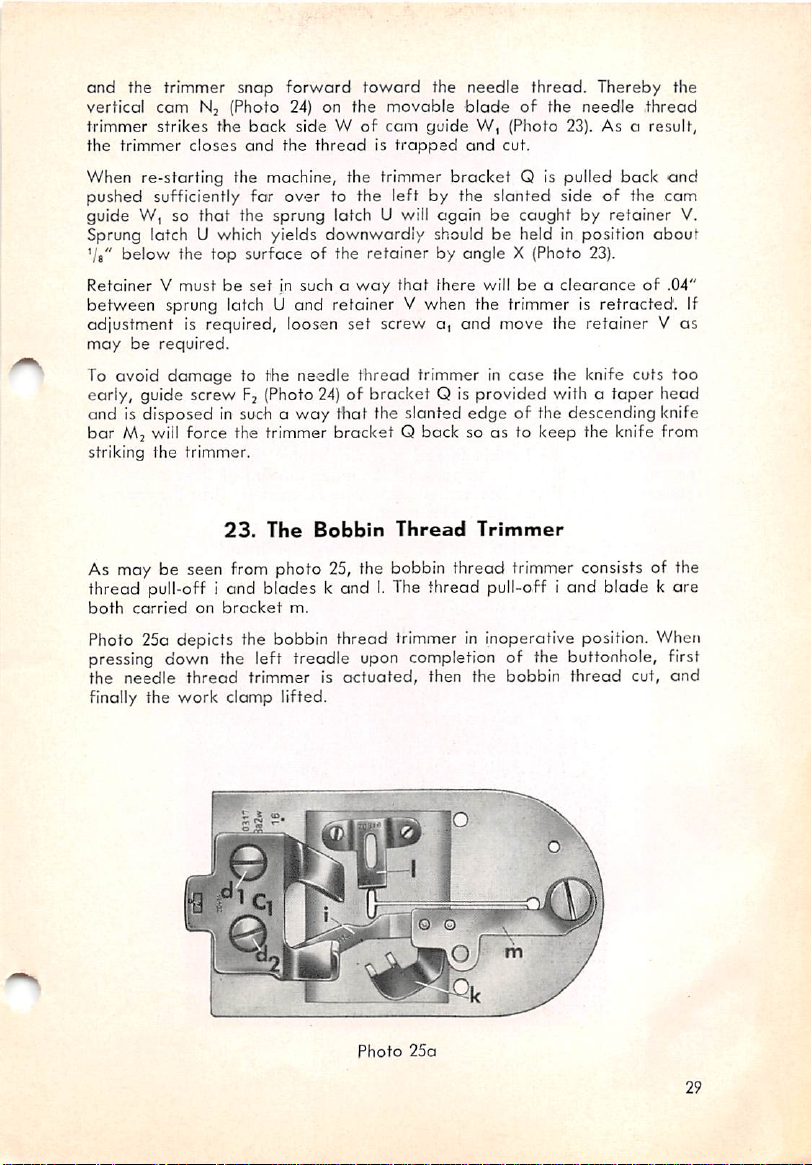
23.
The
way
Bobbin
thread
bracket
that
the slanted
bracket
trimmer in
Q is
provided
edge
Q bock soasto
Thread
Trimmer
case
the knife cuts
with a
taper
head
of the descending knife
keep
the knife from
too
As may be seen from photo 25, the bobbin thread trimmer consists of the
thread pull-off i and blades k andI.The thread pull-off i and blade k ore
both
carried
on
bracket
m.
Photo 25a depicts the bobbin thread trimmer in inoperative position. When
pressing down the left treadle upon completion of the buttonhole, first
the
needle
finally the work clamp lifted.
thread
trimmerisactuated,
then
the
bobbin
thread
cut,
and
V.
If
Photo
25a
29
Page 32

Photo
25b
This
arrangement causes the short end of needle thread to be pulled down
which is left
after
cutting.
When actuating the bobbin thread trimmer, bobbin thread pull-off i pulls
the thread over blade 1 and pulls off the exact amount of thread which is
required for the first stitch of the succeeding buttonhole. Then the trimmer
cuts
the
thread
os
the
two
blades
meet.
Photo 25b shows the final position
30
Photo
after
cutting the thread.
26
Page 33

For
properly
blades
screw
When
bladeisapprox.
injury to
The
compact
needle
loosen
the
mechanism,
enters
24.
To
avoid
first stitchofthe
setting
the
should
n (Photo 26)
exchanging
the
overlap
needle
bobbin
about
and
turn the
blade1,make
—Vu"
thread.
thread
.04" in their final position. To
away
trimmer it should be
crankasmaybeappropriate.
sure
that
the
the cutting
needle
from
disposition of the trimmer mechanism on the underside of the
plate
facilitates removal in
screw
o (Photo 26)
the
make
slotofthe
Pulling
unthreadingofthe
next
sure
bobbin
OK
buttonhole
and
the
the
the
that
case
Needle
Top
needle,
case
the knives need grinding. Simply
needle
the
bobbin
position
plate
bracket.
set
case
Thread
Tension
the
amountofthread
must
be
pulled
Sp, prior to cutting the needle thread. This action is
pin p which is
(Photo
27).
mounted
on lug q,
and
carried
on tension
edge
hole in
screw.
position
and
off
by
performed
Releasing
noted
that
of
the
replacing
properly
top
both
loosen
new
for the
tension
adjust,
ordertoprevent
When
lug
needed
the
by pull-off
release
lever q
Photo
27
Upon
stop
starting the
motion
lever 1
machine
(Photo
by pressing down the right treadle, the
28)
actuates connecting rod s and
tension
hinged
release
lever q whose upper end moves forward to release the pulled-off thread.
Simultaneously, the
top
tension Spi is
engaged.
31
Page 34

Photo
28
Shortly
returned
required
release
tension.
"While the machine is
raised
drive
meansofcrank B,
There should be a
rodVand
32
before
the
machine
to its initial position so
from
top
leverqmoves
tension
q,.Atthe
under
25.
inoperative,
position by locking lever S (Photo 23)
lever
assembly
cannotbeblocked
and
tripping
clearanceof.02"—.04"
slide
collar
x,.
stops,
tension
that
pin p
the
The
same
tension
Knife
(Photo 28)
knife drive connecting
rod
w with
release
can
pull
time
release
Action
and
angleX.Thereby
v/hen the
set
collar x
between
lever
q is
automatically
amountofthread
topoftension
releases
rod
v is held in
camisturned
can
move
the
pin
off
the
lug on
and
feed
knife drive connecting
the
top
the knife
by
freely.
Page 35

When
starling
rod Vwhich falls
buttonhole,
the
machine, locking lever S
and
tripping
pushes slide collar x,
be
pulled
onto
the
rod w
leverHjand
and
somewhat
set
collar x return, driving block z can
actuate
rests
on slide collar Shortly
rod
w is
tripped
away
from the machine until connecting rod v can
smaller
the
knife.
by the
set
collarxby
releases
feed
cam
knife drive connecting
before
completing the
and
with
set
collar x
springy.When
engage
tripping
knife driving
26.
Dismantling
The
PFAFF
3114
hook
hasadivided
To
dismantle
follows:
rest
pin. Remove the bobbin case
two
hook gib screws a, and 02 on the
with the
Igib can be
(Photo 30)
is in line with
the
hook
out.
for
overtothe
Seize
the
Tilt
the
machine
screw
driver (Photo 29).
swung
and
turn the driving pulley until
pointGof
Photo
29
the
Hook
bobbin
cleaningorremoving
cap
After
the
bobbin
left
case.
and
restiton
and
turn the driving pulley until the
back
of the hook can be reached
removing
case
base
pointSof
hook.
of
thread,
the
both
screws,
by its
the bobbin
wooden
center
proceed
machine
the hook
stud A,
case
as
base
33
Page 36
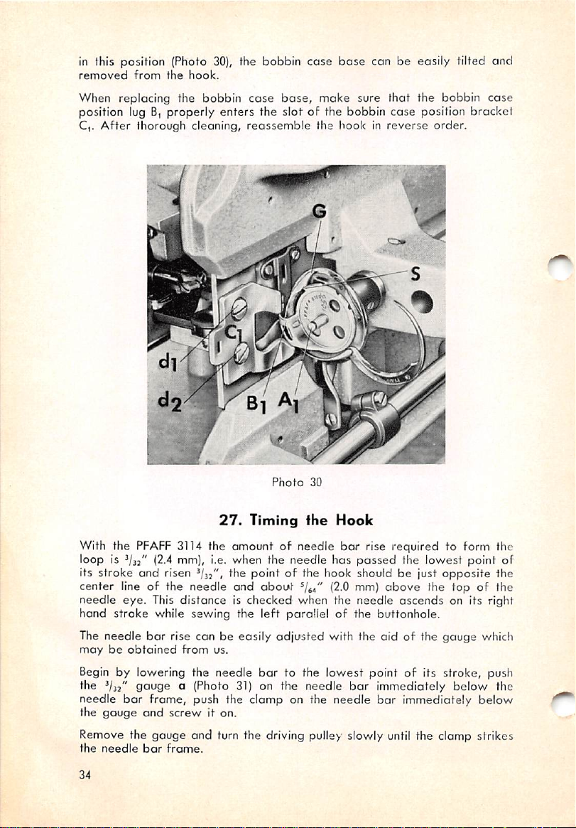
in this position {Photo 30), the bobbin
removed
When
from
the
replacing the
hook.
bobbin
case
base,
case
make
base
con be easily tilted
sure
that
the
bobbin
and
cose
position lug B, properly enters the slot of the bobbin case position bracket
C,.
After
thorough cleaning,
reassemble
the hook in
reverse
order.
Photo
30
27.
Timing
With the
loop is (2,4 mm), i.e. when the needle has
its
center line of the needle
needle eye. This distance is checked when the needle
hand
The needle
maybeobtained
Begin by lowering the needle
the
needle
the
stroke
stroke
gauge
PFAFF
3114 the amount of needle
end
risen the
while
sewing
bor
rise can be easily
from
pointofthe hook shouldbejust
and
about
the
left
us.
bar
gauge
bar
a (Photo 31) on the needle
frame, push the clamp on the needle
and
screw
it on.
the
Hook
(2.0 mm)
parollel of the
adjusted
to the
with the aid of the
lowest
bor
rise required to form the
passed
the lowest point of
above
opposite
the top of the
ascends
buttonhole.
gauge
point of its stroke, push
bar
immediately
bar
immediately
the
on its right
which
below
the
below
Remove the gauge and turn the driving pulley slowly until the clamp strikes
the
needle
bar
frame.
34
Page 37

Photo
31
To turn the
above (point of hook about
screwsb(and
The
needle
hook
on- the hook
bj (Photo 26).
barissetatthe
shaft
^44"
correct
until it is in the position
above top of needle eye), loosen both set
height
when
the
bottomofthe
described
eye is flush with the top edge of the needle guard while the needle
isatthe
The
ensure
point of the hook
In
hook
pull
readjustment of the position
together
lowest
sideways
that
pointofits
adjustment should be
there
is a
and
stroke.
clearance
the needle.
of
made
about
with particular
.004"
(0.1
mm)
care
between
so as to
order to exchange the hook, loosen both set screws c, andCjon the
shaft
collor (Photo 26), remove bobbin
case
position
brackerC,and
the hook forward out of its mount on the shaft. To save lengthwise
with its
base
bracket,
by loosening screws d,
it is
advisable
and
dj.
to remove
needle
bar
the
same
35
Page 38

i
Photo
32
36
Page 39

28.
Regulating
The
amountofpressuretobe
occordcnce
thumb
such a
fabric
with
sorewontopofthe machine
mannerasto
puckeraswellaspoor
the
ensure
29.
To
absorb
stop
of
the
The
position and the needle
highest
the
motion, a
machine.
machineisblocked
pointofits
momentum
powerful
stroke.
the
material
perfect
Changing
of
buffer
when
bar
has
Pressure
exerted
to
be
sewn.Bytightening
arm,
feeding
buttonhole
the
the
machine
spring is
the
take-up
descended
by
the
the
seams.
Butter
provided
on
the
Material
work
clomp
pressure
of the
canberegulated
material
Spring
ond
has
about
reduce
almost
the
in the
rear
reached
.118" (3.0 mm) from the
shouldbeset
the
presser
andtoprevent
impact
on
driving pulley
its
highest
in
bar
in
the
The buffer spring is
after
some
causes
take-upinvarying
low
needle
In
ordertoreplace
Dj
and
take
After
ring G,
timeasa
irregular stopping of the machine, leaving the needle
when
the machine
thread
Ei (Photo 32),
off
the hinged
removing the four
and
stop
The new spring is inserted
compressed
To
facilitate
sufficiently to permit inserting the
exposed
resultoffair
positions. Thus it
trimmer.
exchanging the
stops
the
remove
stop
cam H,
broken
motion
set
and
to excessive stress
wear
that
screws
between
may
the
needleisdamagedorbroken
buffer
and
brake
f,,
spring, loosen
f2,,
the
screwsJiand
remove
the
buffer
spring, it is
special wrench which we will furnish on
buffer
spring. As shown in
the rim of the
against
rear
the bearing
stud of the wrench
wrenchinyour
left
the buffer spring, until the Novotex
that
the straight side of the spring
land
screwonstop
and
brake
lever
assembly.
photo
driving pulley
bracket
and
push the wrench on the
hand
33,
and
0|.
Then slide the loose spring
and
pressitstraight
segment
rest
cam
and
cap
ring
insert
turn Ihe pulley until punch M,
faces
and
and
and
tear.Abrokenorworn
occur
e,,
lever
fj and (Photo 32),
broken
two
spring
may
that
the
both
pull
out
assembly.
buffer
rests
Novotex
recommended
order,
a punch info hole L,
together with the new
top
shaft
down,
can be inserted.
the
Novotex
mount the hinged
slacken or
needle
tension springs
hinge
spring.
Kt (Photo 33)
bar
pin F,,
take
bar
break
spring
and
by the
off
Ihc
is so
end
cap
and
segment Jj.
to use a
located
rest
on
on
resl^
ihe
hub. Take the
thus compressir^g
Make
sure
segment. Replace
stop
motion
37
Page 40
Photo
33
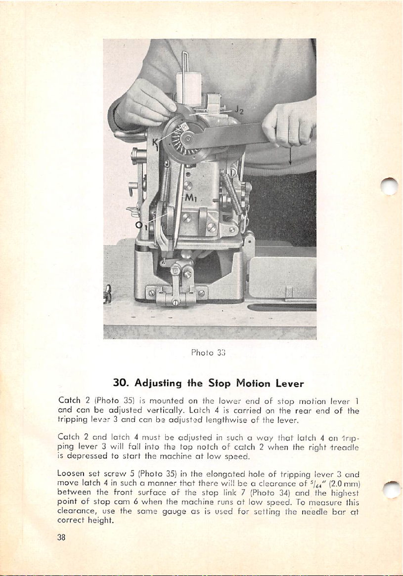
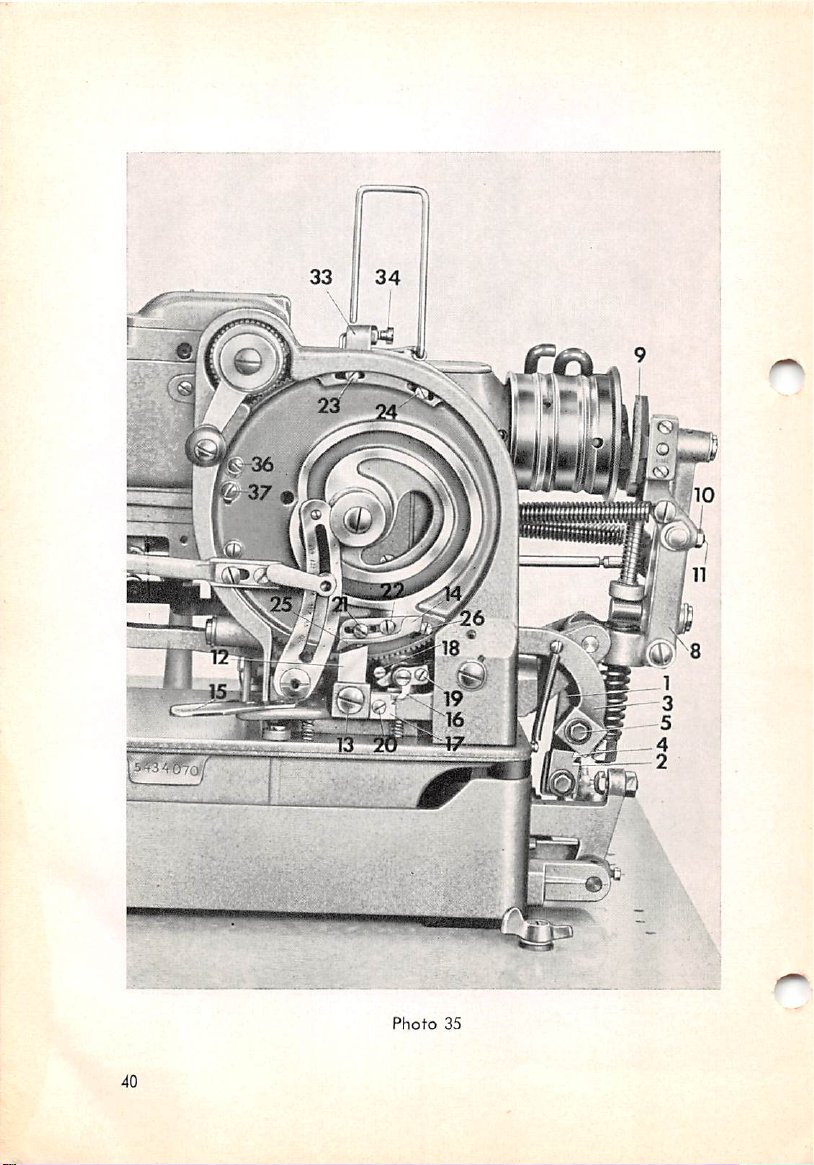
30.
Adjusting
Catch 2 (Photo
and con be
tripping lever 3 end can be
35)
odjusted
is mounted on the lower end of stop motion lever 1
vertically. Latch 4 is
fhe
adjusted
Stop
Motion
carried
lengthwise of the lever.
Lever
on the
rear
endofthe
Catch 2 and latch 4 must be adjusted in such a way that latch 4 on trip
ping lever 3 will fall into the top notch of catch 2 when the right
is
depressedtostart
the machineatlow speed.
treadle
Loosen
move latch 4 in such a manner that there will be a clearance of
between the front surface of the stop link 7 (Photo
point of
set
screw 5 (Photo
stop
cam 6 when the machine runsatlow
35)
in the elongated hole of tripping lever 3 and
34)
^1^,"
and the highest
speed.Tomeasure
clearance, use the same gauge as is used for setting the needle
correct
38
height.
(2.0
bar
mm)
this
at
Page 41

In
case
the
stop
yield sufficiently when falling into
31.
Brake
lever
(inxisssf
facesofbrake
when
and
regulate
8 (Photo 35)
the machine runsatlow
shoe9and
set
screw
too
Adjusting
mustbeadjusted
the
driving
11 in the middleofbrake
Phofo
34
dose
to the
the
stop
the
Brake
pulley
speed.Toset
1
stop
ccm, the former connot
cam
and
may
break.
Lever
in such a
ore
about
this
manner
.275" (7.0 mm)
distance,
lever 8.
that
itie
sur
loosen nut 10
aport
Brake lever 8 is in the
driving pulley
Tripping lever 3 (Photo 35) should be
has
been
another
properly
proper
32.
Adjusting
setasinstructed in Section 30.
position if it can be pulled
(2.0 mm)
when
the
adjusted
Tripping
the machine is
Lever
only
after
inoperative.
stop
Tripping dog 12 is carried on the front end of tripping lever 3.
ing screw 13, this tripping
willbea
clearanceof.04" (1.0 mm)
segment 14 when the machine
dog
should be
between
has
stopped
adjusted
in height so
its tip
and
that
In this position, latch 4 of
tripping lever 3 should rest on catch 2
away
from the
motion lever 1
After
loosen
that
of tripping
there
39
Page 42
w
Photo
35
40
Page 43

When running the machine of low speed, latch 4 must enter the top notch
of catch 2;athigh
To
adjust
switch
position
the
off
the
showninphoto
speed,
distance
machine
33.
Adjusting
it must fall into the lower notch.
between
40.
and
the tripping
turn
the
the
crank
Hand
dog
until
Stop
and
the tripping
the
Lever
feed
cam
segment,
is in
the
Hand stop lever 15 (Photo
35)
carries a spring-loaded latch 16 which
p>ust
engage the vertically adjustable catch 17 mounted on the tripping lever 3.
Stud 18 is
ways
For adjustment, loosen
sideways as may be required to ensure
selyontime.
After loosening screw 20, catch 17 can be adjusted in height so
disposed
motionofthe
on the left of latch 16 which serves to limit the side
latch.
set
screw 19 In the
elongated
that
slot and move latch 16
it will engage catch 17 preci
that
latch 16
wilt engage in the lower notch of catch 17 and the speed of the machine
will be reduced to half upon pressing down hand stop lever 15 once (while
machine is switched on). When in this position, latch 4 of tripping lever 3
is engaged in the top notch of catch 2 (Photo
35).
Upon depressing hand
i
Photo
m
36
41
Page 44

stop
(ever 15 the
tripping lever 3 is tripped
stops
the
machine.
34.
second
time, latch 16 falls into the
Adjusting
and
the
the
stop
Stop
motion
Tripping
and
top
notch of
brake
lever assembly '/a
Segment
catch
17,
The function of the stop tripping segment may be seen from photos 37,
38, 39
and
40.
In photo 37, the front edge of stop tripping segment 14 on the feed cam,
which
moves counter-clockwise, has reached tripping dog
12.
Photo
3/
Photo
33
42
Page 45
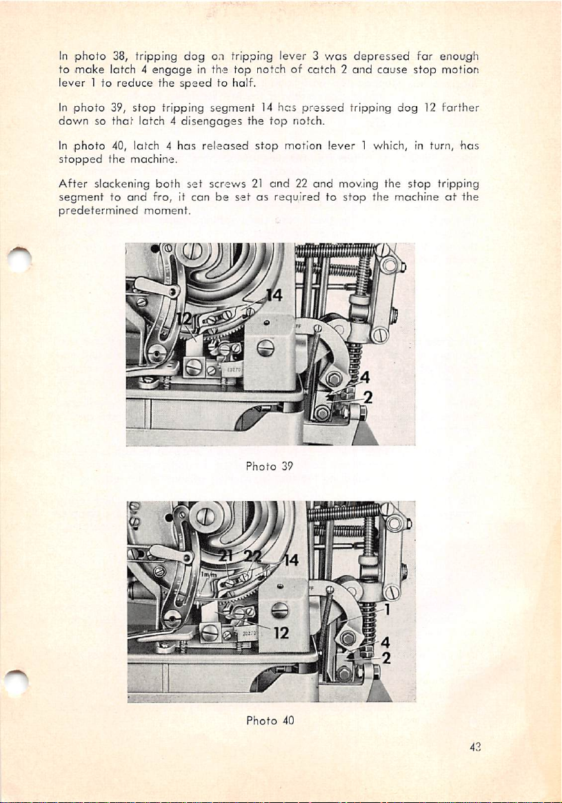
In
photo
to moke iotch 4
lever 1 to
In
downsothat
In
stopped
After
segmenttoand
predetermined
38, tripping dog on tripping lever 3
reduce
photo
39,
stop
photo
40, latch 4
the machine.
slackening
engage
latch4disengages
fro, it conbesetasrequiredtostop
moment.
in the top notch of catch 2
the
speed
to half.
tripping
both
segment14has
the
has
released
set
screws21and22and
top
stop
was
pressed
notch.
motion
n.
depressed
and
tripping
lever
1 which, in turn,
moving
the machineatthe
for enoi/g'h
cause
stop
dog12farther
the
stop
nnotion
has
tripping
Photo
39
w
CD
m.
Photo
40
43
Page 46
The
final
bar
stitchofthe
always (see Section
machine has stopped too early
to the left accordingly. Conversely, if the
second
bartack
36).
If the last stitch lies too far to the right, the
must
be
modeinthe
and
tripping segment 14 must be moved
last
stitch lies too far to the left,
middleofthe
the tripping segment must be moved to the right in order to make the
machine
Note
narrow
the
you check first
will
This
would
the machine to
speed
stop
earlier.
that
stop tripping segment 14 must be
limits
as,
feed
cam
sufficetomake
adjustment
cause
first.
may
the
35.
otherwise,
become
whether
calls for
rear
be
necessary. For this reason,werecommend
raising or lowering the position of tripping dog 12
the
machine
great
endoftripping fever 3 tobeswung up too
stopped
Adjusting
retimingofall
stop
soonerorlater.
care
since
abruptly
the
Bar
rather
Tripping
adjusted
other
setting
only within certain
motions controlled by
tripping
than
being
dog12too
shifted
Segment
that
high
far
and
to low
The tripping
control
be
adjustedasrequired.
by
screws23and
After
so
that
segments
the
widthofthe
24,
slackening
these
the sewingofthe
which
bartacking
The tripping
that
for
screws,
bars
are
the
mounted
both
will
conformity with the feeding motion.
The
tripping
that
the
ordertoavoid
in
The tripping
enough to ensure
tely
covered
Lug 27
motion
first
36.
(Photo
of
the
segment
bar
for
will
notbesewn
displacing the first
segment
and
for the
that
the first stitches of the first parallel will be comple
thataneat
Adjusting
22) on
the
needle
barinrelcjtion
the
first
second
appearance
the
topofleverHpermitstoadjust
for making the tying stitches in the
In
ordertoenhance
mustbemade
there
must be
ways
motion of the
by lug 27
of
the
whenithas
buttonhole.
the
in the
appearance
centerofthe
absolutelynosideways
guide
roller for the
reachedaposition
on the
stitches
segment
end
barbyscrews25and
bar
tripping
back
have
for the
commenceatthe
bar
shouldbeadjusted
until
after,
bartacking
bar
Needle
to
end
of
the
end
bartack.
the first
stitches to the left.
should trip the machine
of
the
buttonhole
Bar
the
center
bcwtack.
buttonhole,
When
motionofthe
needle
bctf vibration is thus
conforming to the
of the
elongated
first
segments
proper
Zero
line
the
making
needle
feed
cam
slots
and
barissecured
26 [Photo 35).
canbeadjusted
time
in such a
parallel
willbeobtained.
manner
is finished
Lug
the
the
tying
these
bar.
zero
sideways
buttonhole
stitches
stitches
The side
checked
(center) line
of
last
and
and
can
in
early
44
Page 47
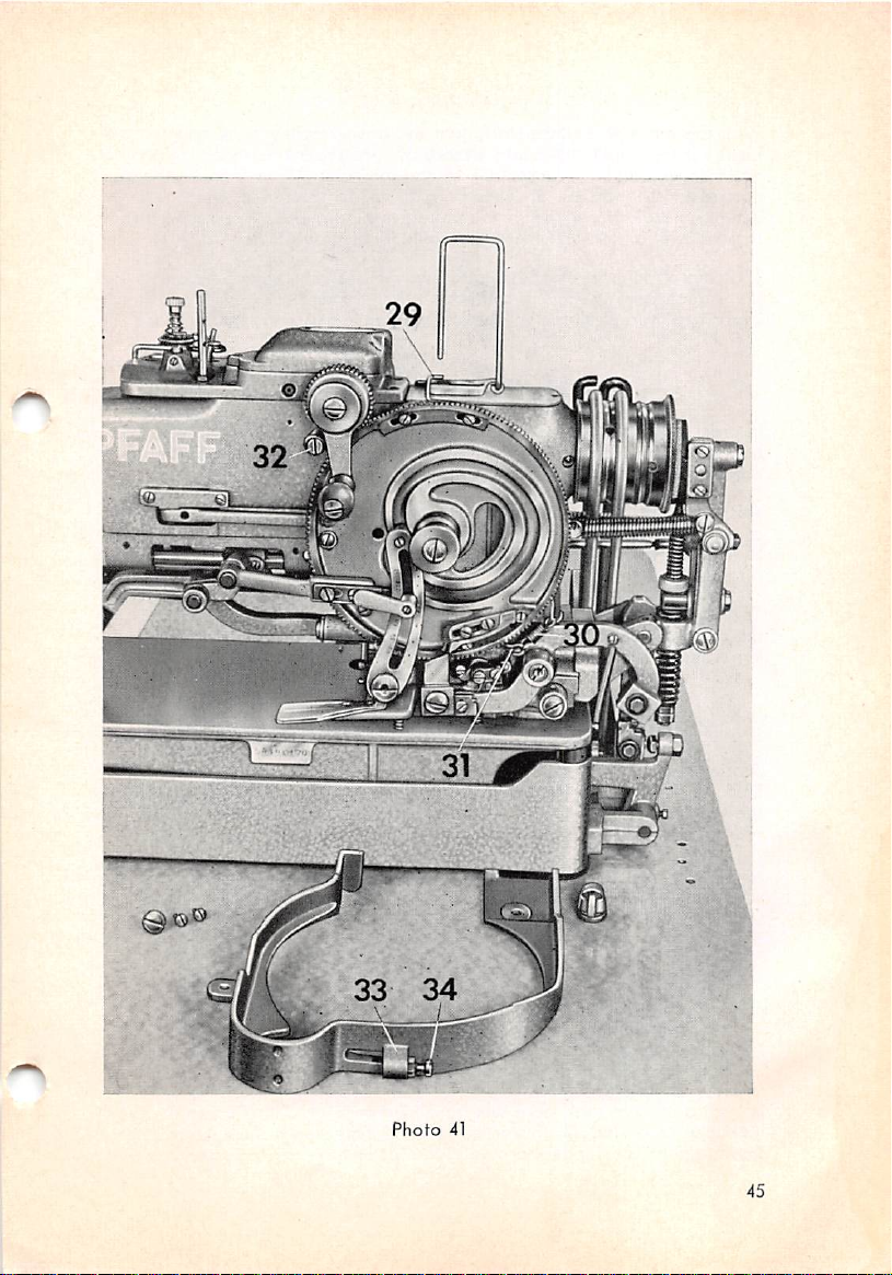
Photo
41
45
Page 48

To
adjust
the
positionoflug 27,
proceedasfollows:
With the machine switched off, turn the driving pulley bock
hand, let the
of
the
not
affect
until the
the
materialinone
needle
needle
marks.
the position of
needle
stitch into a
bar
vibration is
and
Loosen
the
pieceofstiff
nut 28
lever
H. With nut 28
reducedtozero
same
point.
and
move
Tighten nut 28
paper
lug 27
slackened,
and
and
check the position
backsothatitdoes
the
needle
securely.
and
tap
forth by
on the lug
penetrates
The careful
the
stop
important
In
ordertoretain
be
caused
adjustable
This
connected
toothed
retainer
To
regulate
adjustmentofthe
tripping
prerequisites
segment
37.
the
feed
for
The
zero
and
their
obtaining
Feed
cam
against
lug, the
proper
durable
Cam
any
bartack
reverse
tripping
timing relationships
and
neat
buttonholes.
Brake
movement
by the buffer spring when stopping the machine abruptly, an
brakeisprovidedonthe
brakeismade
by
rimofthe
33
with
the tensionofthe spring, turn
of two wire hooks 29
tension
feed
the
other.
spring
30. This spring is
cam
andisfastened
feed
cam.
and
set
31 (Photo 41) which
contained
to
screw
in a
stud32with
34 of
segments
are
which
and
very
may
are
grooveinthe
one
end
and
retainer
33 on
the cam guard inwardly so that the cam will still turn easily without apply
ing
excessive
38.
Tension Sp^ mustbeautomatically
first tying stitch
the top tension Spi
will
cause
force.
Adjusting
after
the
threads
the
Tension
Release
released
campleting the end bartack.
engaged
which is
to
lock
within
set
for a normal
the
material.
when
Tripping
the machine
This
will leave only
thread
Point
makes
tension
the
and
To-time the release of the tension, loosen screws 36 and 37 and move trip
ping point 35 as moy be
correctly if its tip is
tension
release
lever 38 when the machine stops.
appropriate.
opposite
The tripping point 35 is
adjusted
the center of the straight vertical side of
39.
Adjusting
the
StartinglLever
After starting the machine by depressing the right treadle, starting lever 39
is returned to its initial position by pressure spring 40. Its return motion
is checked by stop screw41which,
in such a manner
that
there will be a clearance of .04"
after
loosening nut 42, should be
(1.0
mm) between
set
the adjustable stud 43 of starting lever 39 and stop motion lever 1 when
the machine has stopped, provided the latter has been adjusted correctly.
46
Page 49
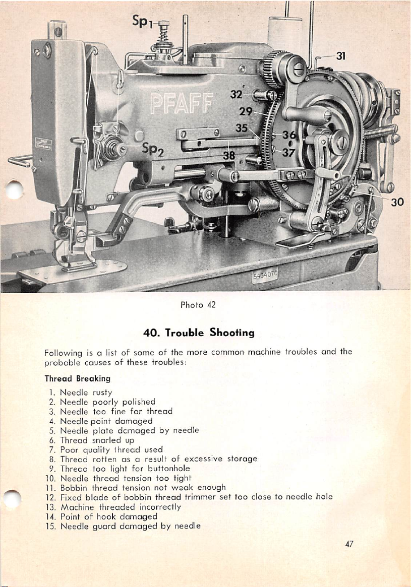
40.
Photo
Trouble
30
42
Shooting
Following
probable
Thread
1.
2.
3.
4.
5.
6.
7. Poor quality
8.
9.
10.
11. Bobbin
12.
13.
14. Pointofhook
is a list of some of the more
couses of these troubles:
Breaking
Needle
Needle
Needle
Needle
Needle
Thread
Thread
Thread
Needle
Fixed
Machine
rusty
poorly
polished
too
fine
point
plate
snarled
for
damaged
dcmaged
up
thread
rotten
asaresultofexcessive
too
light for
thread
tension
threaded
tension
incorrectly
thread
bladeofbobbin
damaged
used
thread
by
needle
buttonhole
too
tight
not
weak
thread
trimmer
15. Needle guard damaged by needle
common
enough
storage
set
machine
too
closetoneedle
troubles end the
hole
47
Page 50

SkippingofStitches
1.
Needle
2.
Needle
3.
Needle
4.
Needle
5.
Needle
6.
Needle
7.
Amountofneedle
bent
set
too
settolow
inserted
too
thick
too
fine
8. Pointofhook
9.
Pointofhook
10. Hook
Faulty
1.
2. Bobbin
3.
4. Needle
5.
6.
Stitch
Needle
Thread
Thread
Thread
needle
guord
Formotion
thread
thread
accumulated
thread
spun unevenly
knotty
high
incorrectly
for
thread
for
thread
bor
set
broken
rise insufficient for
too
for
away
from
proper
needle
bent
tension
tension
gets
too
weak
too
tight
between
tension
discs
caughtatrim of spool (Use spool discs)
loop
formation
Needle
Insufficient Top
(Full
Breakage
1.
2.
3.
4.
5.
Needle
Needle
Needle
Needle
Hook
set
bent
too
worn
blunt
too
fine
close
for
material
to
the
needle
6. Needle thread not threaded through needle
needleispulled
7.
Improper
speed
reached
1.
Machine
2. Line
3.
shaft
Machine
needle
Speed
driving
belts
poorly
over
system
too
belts
too
used
lateornotatall)
too
long
oiled
long
bar
thread guide so that
4. Mechanism gummed by wrong oil (Never use glycerine or castor
5. Feed cam
brake
set
too
tight
6. Thread snarled up between loose and driving pulleys
48
oil)
Page 51
Untidy Buttonhole Cut
1.
Buttonhole
2. Buttonhole knife
knife
blunt
set
too
high
3. Blade groundatwrong angle
4. Distance
5. Buttonhole knife
6. Buttonhole knife
between
buttonhole
jagged
ground
porollsls
excessively
set
7. Distance between buttonhole porallels
8. Insufficient annount of pressure on material
9. Knife slot in needle
plate
damaged
set
too
too
wide
narrow
Needle
Thread
Trimmer
1. Piecesofthread
2.
Trimmer
blades
3. Trapper spring
Fails
jammed
blunt
damaged
between
by needle
4. Trapper spring slockens due to fair
bladesortrapper
wear
and
tear
.*1
Page 52

G.
SEWING
M.
PFAFF
MACHINE
AG,
KAISERSLAUTERN
FACTORY
Certificate
For every PFAFF
TRADE
and
the
name
Sewing
Founded
Machine
1862
of
Guarantee
bearing this
MARK
PFAFF
the factory assumes
and durability.
The Trade Mark and the name
All rights
Nr. 7659 engl. P 656
reserved.
full
guarantee for first-class quality, efficiency
PFAFF
are
registered.
''Vv
PrintedinGermany
 Loading...