

Page 1

-926/06
Supplement to the
Instruction Manual and
Parts List
for the PFAFF 1051, 1053
1181, 1183,
2481
296-12-18 396/002
Beiblatt zur Betriebsanleitung
und Teileliste engl. 02.2001
Page 2

The reprinting, copying or translation of PFAFF Instruction Manuals, whether in whole or in
part, is only permitted with our previous permission and with written reference to the
source.
G.M. PFAFF KAISERSLAUTERN
INDUSTRIEMASCHINEN AG
Postfach 3020
D-67653 Kaiserslautern
Königstr. 154
D-67655 Kaiserslautern
Editing/Illustrations
HAAS-Publikationen GmbH
D-53840 Troisdorf
Page 3

Contents
Contents ................................................................................. Chapter - Page
1 Safety ........................................................................................................................... 1 - 1
1.01 Directives...................................................................................................................... 1 - 1
1.02 General notes on safety................................................................................................ 1 - 1
1.03 Safety symbols ............................................................................................................. 1 -2
2 Control elements......................................................................................................... 2 - 1
2.01 Control device for remaining bobbin thread .................................................................. 2 - 1
2.02 Pedal ............................................................................................................................. 2 - 1
3 Setting up .................................................................................................................... 3 -1
3.01 Winding the bobbin thread / regulating the winder tension .......................................... 3 - 1
3.02 Inserting the bobbin in the bobbin case ........................................................................ 3 - 2
3.03 Inserting the thread in the bobbin case / regulating the bobbin thread tension ............ 3 - 2
4 Sewing ......................................................................................................................... 4- 1
4.01 Sewing with bobbin thread monitoring function ........................................................... 4 - 1
4.02 Sewing with bobbin thread counter function ................................................................ 4 - 2
5 Adjustments ................................................................................................................ 5 - 1
5.01 Parameter settings........................................................................................................ 5 - 1
6 Parts list ....................................................................................................................... 6 - 1
Page 4

Safety
1 Safety
1.01 Directives
1.02 General notes on safety
This machine is constructed in accordance with the European regulations contained in the
conformity and manufacturer’s declarations.
In addition to this Instruction Manual, also observe all generally accepted, statutory and other
regulations and legal requirements and all valid environmental protection regulations!
The regionally valid regulations of the social insurance society for occupational accidents or
other supervisory organizations are to be strictly adhered to!
● This machine may only be operated by adequately trained operators and only after having
completely read and understood the Instruction Manual!
● All Notes on Safety and Instruction Manuals of the motor manufacturer are to be read
before operating the machine!
● The danger and safety instructions on the machine itself are to be followed!
● This machine may only be used for the purpose for which it is intended and may not be
operated without its safety devices. All safety regulations relevant to its operation are to be
adhered to.
● When exchanging sewing tools (e.g. needle, roller presser, needle plate and bobbin), when
threading the machine, when leaving the machine unattended and during maintenance
work, the machine is to be separated from the power supply by switching off the On/Off
switch or by removing the plug from the mains!
● Everyday maintenance work is only to be carried out by appropriately trained personnel!
● Repairs and special maintenance work may only be carried out by qualified service staff or
appropriately trained personnel!
● Work on electrical equipment may only be carried out by appropriately trained personnel!
● Work is not permitted on parts and equipment which are connected to the power supply!
The only exceptions to this rule are found in the regulations EN 50110.
● Modifications and alterations to the machine may only be carried out under observance of
all the relevant safety regulations!
1 - 1
● Only spare parts which have been approved by us are to be used for repairs! We
expressly point out that any replacement parts or accessories which are not supplied by
us have not been tested and approved by us. The installation and/or use of any such
products can lead to negative changes in the structural characteristics of the machine. We
are not liable for any damage which may be caused by non-original parts.
Page 5
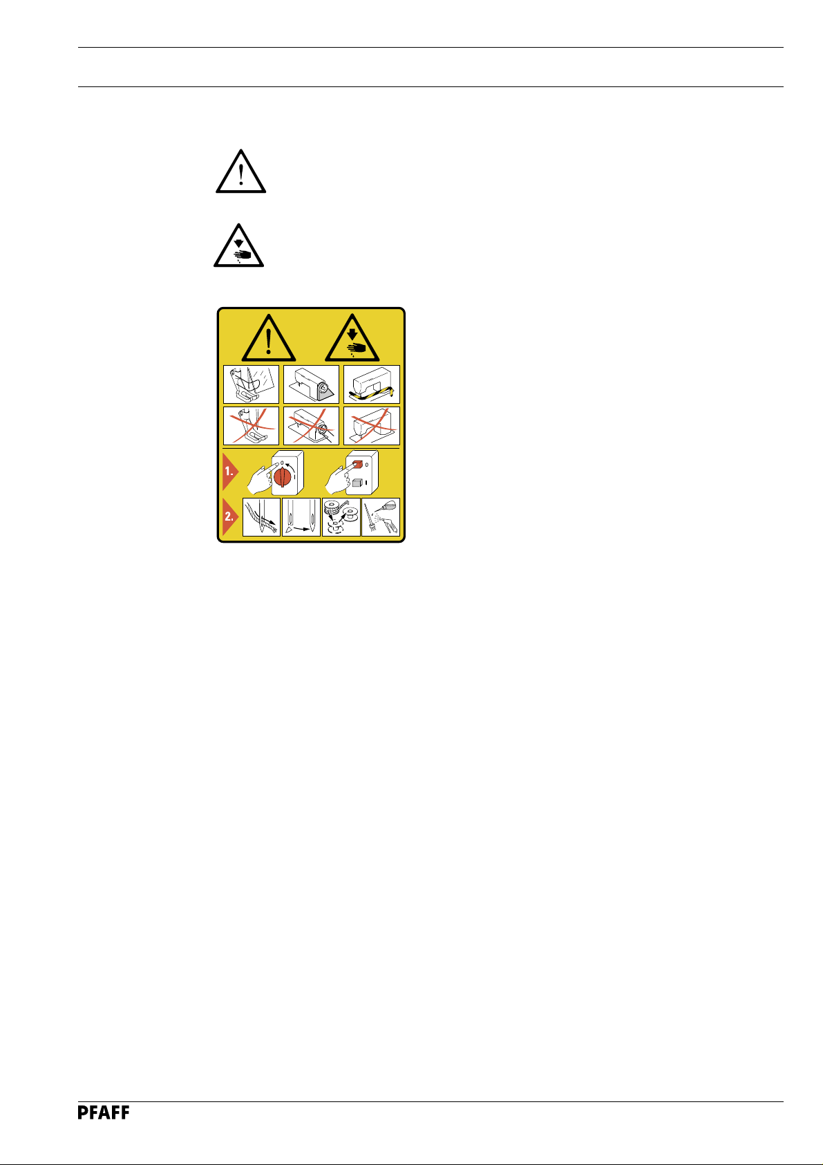
1.03 Safety symbols
Danger!
Points to be observed.
Danger of injury for operating and specialist personnel!
Safety
Caution
Do not operate without finger guard and safety devices.
Before threading, changing bobbin and needle, cleaning
etc. switch off main switch.
I
1 - 2
Page 6

Control elements
2 Control elements
2.01 Control device for remaining bobbin thread
Bobbin thread monitor
● When the use of the last amount of
the remaining thread supply begins, the
LED 1 starts flashing.
● When the remaining thread supply has
been used up, the LED 1 lights up
permanently until the bobbin has been
changed.
Bobbin thread counter
● When the thread counter reaches its
end, the LED 1 starts flashing.
● If sewing continues without the bobbin
being changed, the LED 1
1
permanently until the bobbin is changed.
remains on
Fig. 2 - 01
2.02 Pedal
To select thread monitoring or
thread counting see Chapter
5.01 Parameter settings
0 = Neutral position
1 = Sewing
2 = Raise presser foot
3 = Trim sewing threads / reset
0
1
bobbin thread monitor or bob
bin thread counter
..
.
..
2 - 1
2
3
Fig. 2 - 02
Page 7

3 Setting up
.01 Winding the bobbin thread / regulating the winder tension
3
Setting up
1
59_03
3
1
2
4
-
6
+
59_01
5
59_04
Fig. 3 - 01
● Place empty bobbin 1 on winder spindle 2 with the residual thread chamber pointing to
the outside.
● Insert the thread as shown in Fig. 3 - 01
around bobbin 1.
● Engage the bobbin winder by pressing spindle 2 and lever 3 simultaneously.
The bobbin fills during sewing.
If the machine is only operated in order to fill the bobbin (without sewing), a
bobbin case must be inserted in the hook!
If this is not done, a jammed thread may damage the hook!
● The tension of the thread wound onto bobbin 1 can be set with milled screw 4.
● The bobbin winder stops automatically when sufficient thread has been wound onto bobbin 1.
If the thread is wound unevenly:
● Loosen nut 5.
● Turn thread guide 6 as required.
● Tighten nut 5 again.
and wind the thread a few times clockwise
3 - 1
Page 8

Setting up
3.02 Inserting the bobbin in the bobbin case
● Insert bobbin 1 in the bobbin case 2 as
shown in Fig. 3 - 02.
2
1
Fig. 3 - 02
3.03 Inserting the thread in the bobbin case /
regulating the bobbin thread tension
● Guide the thread through the slit and
● Adjust the thread tension by turning
5 cm
-
below the spring as shown in Fig. 3 - 03.
screw 1.
When the thread is pulled, the
bobbin must move in the
direction of the arrow.
3 - 2
1
+
Fig. 3 - 03
Page 9

4 Sewing
4.01 Sewing with bobbin thread monitoring function
The bobbin thread monitoring function via sensor is activated, when parameter
"660" is set at value "1". The number of stitches, which can sewn with the
remaining thread, is entered under parameter "760", after the bobbin thread
monitoring function has responded.
You will find more information about parameter settings in Chapter 5.01
Parameter Settings.
● If, during sewing, the bobbin thread
monitor recognises that the residual
thread supply is being used, LED 1 starts
flashing.
Sewing can continue without a bobbin
change. From this point on the pre-set
number of stitches, which can be sewn
with the remaining thread, are counted.
● Once this number of stitches has been
sewn, the machine stops automatically
and LED 1 lights up permanently. The
bobbin must be changed.
1
2
● After the bobbin has been changed, the
bobbin thread monitoring function is
reset with pedal function "3", see
Chapter 2.02 Pedal.
Sewing
Fig. 4 - 01
By pressing key 2 and at the same time activating pedal function "3", the bobbin
thread monitoring function can be reset at any time.
4 - 1
Page 10

Sewing
4.02 Sewing with bobbin thread counter function
The bobbin thread monitoring function via counter is activated, when parameter
"660" is set at value "2". The total number of stitches, which can sewn with one
bobbin, is entered under parameter "760".
You will find more information about parameter settings in Chapter 5.01
Parameter Settings.
● Once the total number of stitches has
been sewn, the machine stops
automatically and LED 1
● If sewing continues without a bobbin
change, LED 1 lights up permanently.
● After the bobbin has been changed, the
bobbin thread counter function is reset
to the pre-set value with pedal function
"3", see Chapter 2.02 Pedal.
starts flashing.
Fig. 4 - 02
1
2
By pressing key 2 and at the same time activating pedal function "3", the bobbin
thread counter function can be reset at any time.
4 - 2
Page 11

5 Adjustments
.01 Parameter settings
5
5.01.01 Selecting and altering parameters
● Switch on the machine.
Adjustments
● Press the Parameter input
key (LED on).
100
● By pressing +/- on the P key select the desired group, e.g. "700".
700
● By pressing +/- on the S key select the desired parameter, e.g. "760".
760
● Set the desired value (e.g. number of stitches for bobbin thread monitor function) by
pressing +/- (L key).
● Save the input by ending the parameter input (LED off).
For further displays and information see the Motor Service Manual.
5 - 1
Page 12

Parts list
PFAFF 1051;1053
PFAFF 1181;1183
PFAFF 2481
95-734 419-91
95-734 377-05
11-108 093-25
91-004 181-05 (PFAFF 1051;1181;2481)
91-262 806-05 (PFAFF 1083;1183)
11-210 084-25 (2x)
95-734 378-91
95-774 361-05
95-774 366-25 (PFAFF 1051;
1181;
2481)
95-774 364-25 (PFAFF 1083;
1183)
6 - 1
71-710 000-57
95-774 365-91 (PFAFF 1051;1181;2481)
95-774 362-91 (PFAFF 1083;1183)
Page 13

PFAFF 1051;1053
PFAFF 1181;1183
95-784 322-91
Parts list
6 - 2
Page 14

Parts list
PFAFF 2481
95-784 314-91
91-291 973-91
6 - 3
Page 15

Notes
Page 16

 Loading...