

Page 1

-948/51
Supplement to the instruction
manual and parts list for the series
1050, 1180, 5483
296-12-18 749/002
engl 04.2003
Page 2

Reprinting, copying or translation of PFAFF instruction manuals, whether in whole or in part,
is not permitted without our prior permission and not without written indication of the
source.
PFAFF Industrie Maschinen AG
Postfach 3020
D-67653 Kaiserslautern
Königstr. 154
D-67655 Kaiserslautern
Editing/illustrations
HAAS-Publikationen GmbH
D-53840 Troisdorf
Page 3

Index
Contents ................................................................................. Chapter - Page
1 Proper use.................................................................................................................... 1 -1
2 Controls ....................................................................................................................... 2- 1
2.01 Puller functions .............................................................................................................2- 1
2.02 Lateral alignment of the puller....................................................................................... 2 - 1
2.02 Control panel................................................................................................................. 2 - 2
2.02.01 Screen displays ............................................................................................................. 2 - 2
2.02.02 Function keys................................................................................................................ 2 - 2
2.02.03 Selecting and altering parameters................................................................................. 2 - 5
2.02.04 Selecting the user level................................................................................................. 2- 6
3 Commissioning ........................................................................................................... 3 - 1
3.01 Basic position of the machine drive .............................................................................. 3 - 1
3.02 Testing the function of the start inhibitor ...................................................................... 3 - 2
4 Setting up .................................................................................................................... 4 -1
4.01 Entering the puller feed stroke (stitch length) ............................................................... 4 - 1
4.02 Setting the puller pressure............................................................................................ 4 - 1
4.03 Entering the maximum speed ....................................................................................... 4 - 2
4.04 Entering the start and end backtacks............................................................................ 4 - 2
4.05 Setting the stitch counting function for the bobbin thread control ................................ 4 - 3
5 Sewing ......................................................................................................................... 5- 1
5.01 Manual sewing.............................................................................................................. 5 -1
5.02 Programmed sewing..................................................................................................... 5 - 2
5.03 Error messages............................................................................................................. 5 -3
6 Parameter Settings...................................................................................................... 6 - 1
7 Software-Update ......................................................................................................... 7 - 1
8 Reset / Kaltstart ........................................................................................................... 8 - 1
9 Partslist ........................................................................................................................ 9 - 1
Page 4
Proper use
1 Proper use
1.01 Using standard presser feet
With the puller the workpiece is fed continously, which makes it possible to sew to a great
extent without shifting and puckering. The puller’s linear motor enables an individual
clearance space between the needle plate and the puller roller.
All adjustments, such as e.g. puller feed stroke, puller roller clearance etc. are carried out by
altering the parameter values, see Chapter 2.03.03 Selecting and altering parameters.
Any use of these machines which is not approved by the manufacturer shall be
considered as improper use! The manufacturer shall not be liable for any damage arising out of improper use! Proper use shall also be considered to include
compliance with the operation, adjustment, service and repair measures specified by the manufacturer!
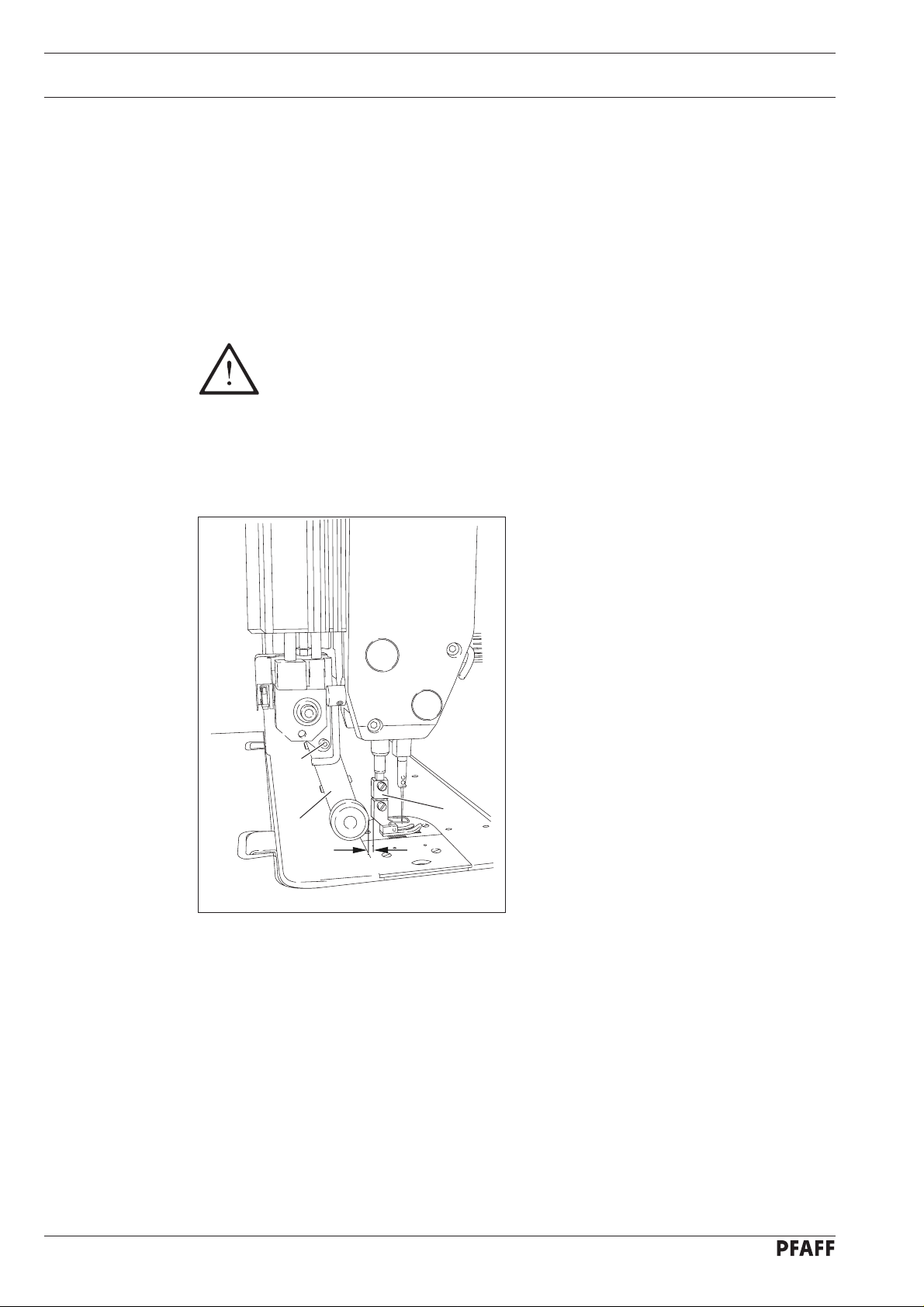
● With the adapter 1 which belongs to the
accessories, standard presser feed can
also be used.
● Mount adapter 1 as shown in Fig. 1-01.
● Loosen screw 2 and push puller arm 3
back.
● Screw the presser foot onto adapter 1.
● Adjust puller arm 3 so that there is a
clearance of approx. 1 mm between the
puller roller and the presser foot.
2
● Tighten screw 2.
1 - 1
3
1
1 mm
Fig. 1 - 01
Page 5
2 Controls
2.01 Puller functions
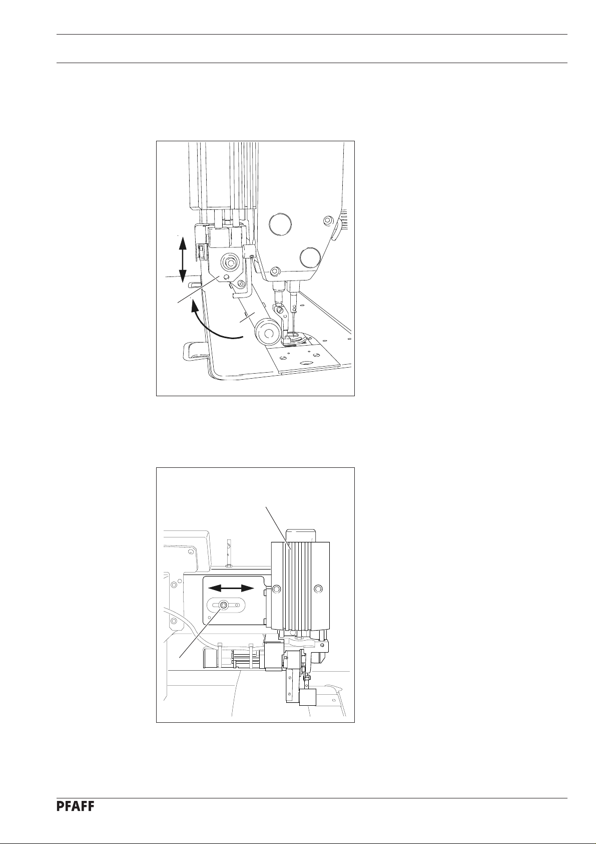
1
2
Fig. 2 - 01
Controls
Engaging/disengaging the puller
● Raise the puller drive unit 1 until it locks
into place and swing puller arm 2 back as
far as possible. To engage the puller,
follow the instructions in the reverse
order.
Switching the puller on/off
● The puller is automatically switched on or
off when the puller unit is engaged or
disengaged.
Setting the puller feed motion
● The feed motion of the puller is set by
means of parameters (see Chap. 1.06
Parameter settings and the Motor
Instruction Manual)
2.02 Lateral alignment of the puller
2
1
Fig. 2 - 02
● Loosen screw 1.
● Align puller 2 with the material ply.
● Tighten screw 1.
2 - 1
Page 6
Controls
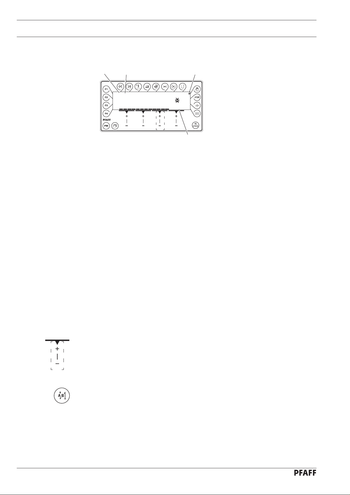
2.02 Control panel
12
4000 PUL 12%
The control panel consists of display 1 and the function keys described below. The display 1
consists of a two-line alpha-numerical LCD display with 16 symbols per line. The texts 3
show the respective status of the function keys and the operating status of the machine.
The control panels switches on all LCD-segments and the horn automatically for a short time
during the power-on phase, after which the lettering PFAFF appears on the display, until the
higher-ranking control unit sends commands to the control panel.
2.02.01 Screen displays
3
Speed
2.0
4
● Activated functions are displayed with a triangular marking 2 below or next to the
respective function key.
● In the sewing mode all relevant sewing data is displayed and these can be changed
directly, depending on the status of the machine, see also Chapter 5 Sewing.
● During the parameter input the selected parameter number with the corresponding value
is displayed, see Chapter 2.02.03 Selecting/changing parameters.
2.02.02 Function keys
The function keys described below are used basically to switch machine functions on and
off.
If a corresponding value has to be set for the activated function, this is carried out with the
corresponding +/- key. By pressing and holding the corresponding +/- key, the appropriate
numerical value 4 is changed slowly to begin with. If the corresponding +/- key is held down
longer, the values change more quickly.
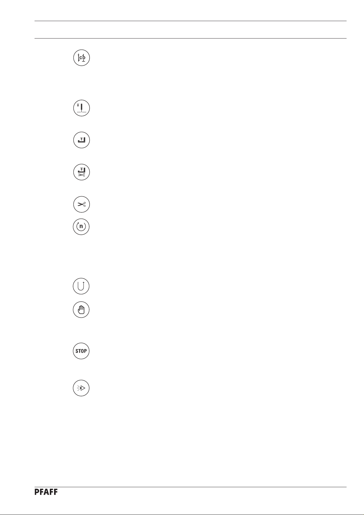
Start backtacks
If this key is pressed, the backtacks at the beginning of the seam (start backtacks) are
switched on or off. The number of forward stitches (A) or reverse stitches (B) for the start
backtacks can be changed by pressing the +/- key underneath. To convert from double
backtack to single backtack set the corresponding number of stitches at zero.
2 - 2
Page 7
Controls
End backtacks
● If this key is pressed, the backtacks at the end of the seam (end backtacks) are switched
on or off. The number of reverse stitches (C) or forward stitches (D) can be changed by
pressing the +/- key underneath. To convert from double backtack to single backtack set
the corresponding number of stitches at zero.
Needle position
● If this key is pressed the corresponding function is switched on or off. When the function
is switched on, the needle positions at t.d.c. after sewing stops.
Foot position after stop
● If this key is pressed the corresponding function is switched on or off. When the function
is switched on, the presser foot is raised after sewing stops.
Foot position after trimming
● If this key is pressed the corresponding function is switched on or off. When the function
is switched on, the presser foot is raised after thread trimming.
Thread trimmer
● If this key is pressed the thread trimming function is switched on or off.
Speed
● If this key is pressed the corresponding function is switched on or off. In the seam
program the speed is not dependent on the pedal. When the function is switched on, the
speed cannot be adjusted by pedal. Sewing can only be carried out at the set maximum
speed.
● If the function is switched off, the speed up to maximum speed is adjusted by the pedal.
Reverse sewing
● If this key is pressed the reverse sewing function is switched on or off.
Manual seam
● If this key is pressed the machine switches to manual sewing. When the function is
switched on, the move to the next seam section is not carried out by stitch counting or
sensor, but manually with the use of the pedal.
Stop
● If this key is pressed the corresponding function is switched on or off. When the function
is switched on, the machine stops automatically at the end of a seam section.
Sensor
● If this key is pressed the corresponding function is switched on or off. When the function
is switched on, the machine stops when the sensor recognises the edge of the material.
2 - 3
Page 8

Controls
Stitch counting
● If this key is pressed the corresponding function is switched on or off. The value for the
compensating stitches can be changed immediately with the corresponding +/- key.
When the function is switched on, the machine moves to the next seam section after
sewing the number of stitches entered.
TE/Speed
● In the programmed sewing mode, the number of stitches is entered by stitching them off.
● If this key is pressed once, the machine changes to parameter input.
● If this key is pressed twice (within 5 seconds) the machine changes to stitch input.
Scrolling
● If this key is pressed in the programmed sewing mode, the machine scrolls through the
input menus on the display.
PM
● If this key is pressed the programmed sewing function is switched on or off. When the
function is switched on, the letters "PM" appear on the display of the control panel. The
parameters related to the program are shown in the alpha-numerical part of the display.
F1
No function assigned
F2
No function assigned
F3
No function assigned
F4
No function assigned
2 - 4
Page 9

2.02.03 Selecting and altering parameters
● Switch on the machine.
● Press the TE/Speed key to call up the parameter input function.
TE
No
200
No
● By pressing the corresponding +/- key select the desired parameter group, e.g. "600".
TE
No
600
Controls
● By pressing the corresponding +/- key select the desired parameter, e.g. "660" for the
No
bobbin thread monitoring function.
TE
No VAL
660 1
● By pressing the corresponding +/- key set the desired value for the parameter selected,
VAL
e.g. "2" for the "bobbin rest thread counter on" function.
TE
No VAL
660 2
● Press the TE/Speed key to take over the value and change to the sewing mode.
2 - 5
Page 10

Controls
2.02.04 Selecting the user level
● Switch on the machine.
● Press the TE/Speed key to call up the parameter input function.
TE
No
101
No
● By pressing the corresponding +/- key select the parameter group "700".
TE
No
798 0
A
● By pressing the corresponding +/- key select the parameter "798".
No
TE
No VAL
798 1
B
VAL
● By pressing the corresponding +/- key select the desired user level:
"0" = operator level A
"1" = technician level B
"11" = service level C
The respective level is displayed on the screen. (see arrow)
● Press the TE/Speed key to take over the value and change to the sewing mode.
2 - 6
Page 11

3 Commissioning
3.01 Basic position of the machine drive
● Switch on the machine.
Speed
4000 PUL 12%
2.0
● Press the TE/Speed key to call up the parameter input function.
● Select the technician level B (value "1") with parameter "798", see Chapter 2.03.04
Selecting the user level.
Commissioning
TE
No VAL
B
798 1
No
● By pressing the corresponding +/- key select the parameter group "700".
TE
No
700 0
B
● Sew a stitch by operating the pedal.
● Turn the balance wheel in the direction of sewing until the needle point is level with the
top edge of the needle plate.
● Press the TE/Speed key to take over the setting and to conclude the input.
3 - 1
Page 12

Commissioning
3.02 Testing the function of the start inhibitor
● Switch the machine on at the main switch and tilt back the sewing head.
● If the message does not appear, check the setting of the safety switch.
● Set the sewing head upright again and acknowledge the error message by pressing the
ERROR
E009
PRESS TE-SPEED
The error message "E009" must appear on the control panel.
TE/Speed key. The machine is ready for operation again.
3 - 2
Page 13

4 Setting up
4.01 Entering the puller feed stroke (stitch length)
● Switch on the machine.
Speed
4000 PUL 12%
2.0
● Enter the feed stroke by pressing the corresponding +/- key.
The puller feed stroke setting must match the stitch length setting of the basic
machine!
Set ting up
4.02 Setting the puller pressure
Speed
4000 PUL 12%
● Switch on the machine.
● Set the desired puller pressure by pressing the corresponding +/- key.
The current puller pressure can be read on the display as a bar graph and as a value
(in %).
2.0
4 - 1
Page 14

Setting up
4.03 Entering the maximum speed
4.04 Entering the start and end backtacks
● Switch on the machine.
Speed
4000 PUL 12%
2.0
● Enter the maximum speed by pressing the corresponding +/- key.
● Switch on the machine.
2 x
● Select the manual sewing mode by pressing the "PM" key.
● Press the TE/Speed key twice to select the input menu for start and end backtacks.
In the programmed sewing mode it is possible to call up the input menu for
start and end backtacks by pressing the scroll key, see Chapter 5.02
Programmed sewing.
PM
A B C D
1 1 1 1
● By pressing the corresponding +/- key select the desired value for the number of forward
A
stitches (A) of the start backtack.
● By pressing the corresponding +/- key select the desired value for the number of reverse
B
stitches (B) of the start backtack.
4 - 2
● By pressing the corresponding +/- key select the desired value for the number of reverse
C
stitches (C) of the end backtack.
● By pressing the corresponding +/- key select the desired value for the number of forward
D
stitches (D) of the end backtack.
● Press the TE/Speed key to store the selected setting and to conclude the input.
Page 15

Set ting up
4.05 Setting the stitch counting function for the bobbin thread control
● Switch on the machine.
● Press the TE/Speed key to call up the parameter input function.
TE
No
200
No
● By pressing the corresponding +/- key select the parameter group "700".
TE
No
700
No
VAL
● By pressing the corresponding +/- key select the parameter "760".
TE
No VAL
760 1
● By pressing the corresponding +/- key set the number of remaining stitches, which can
be sewn after recognition by the bobbin thread monitor. Among other things the setting
depends on the thread size.
● Press the TE/Speed key to take over the value and change to the sewing mode.
The remaining bobbin thread counter can only be used, when parameter "660" is
set at the value "1" or "2".
4 - 3
Page 16

Sewing
5 Sewing
5.01 Manual sewing
In the sewing mode all relevant adjustments for the sewing operation are shown on the
display and can be altered directly. Functions can be switched on and off by pressing the
key.
In this mode a difference is made between manual sewing and programmed sewing. To
change from manual to programmed sewing, press the PM key. In programmed sewing the
text "PM" appears on the display.
After the machine has been switched on, the maximum speed, the puller feed stroke and
the puller pressure can be adjusted with the corresponding +/- keys.
Speed
4000 PUL 12%
2.0
Further functions in manual sewing, also see Chapter 2.02.02Function keys:
Start backtacks on/off Presser foot raised at end of seam on/off
End backtacks on/off Thread trimming on/off
Needle position raised on/off Sensor on/off
Presser foot raised on/off
On the basic machine the stitch length is adjusted with the balance wheel.
The stitch length for the puller is adjusted on the control panel
5 - 1
Page 17

5.02 Programmed sewing
In the programmed sewing mode 99 programs, each with 9 seam sections and 999 stitches,
can be programmed.
The fixed programs are used for the quick and easy production of seams with different
numbers of stitches. The pedal setting „0“ is used to switch to the next seam section.
After the machine has been switched on and the programmed sewing mode has been
selected with the PM key, the display appears for selecting the program number, seam
section and number of stitches.
11 13
Sewing
PM
With the scroll key other menus can be selected for entering the values for start and end
backtacks and the maximum speed in the corresponding seam section.
PM
1000 5 0
Further functions in programmed sewing, also see Chapter 2.02.02 Function keys:
Start backtacks on/off Seam section speed on/off
End backtacks on/off Reverse sewing direction on/off
Needle position raised on/off Manual sewing on/off
Presser foot raised on/off Stop on/off
Presser foot raised after Sensor on/off
thread trimming on/off
Thread trimming on/off Stitch count on/off
5 - 2
Page 18

Sewing
5.03 Error messages
If a fault occurs, the text "ERROR" appears on the display, together with an error code and
short instructions. An error message is caused by incorrect settings, faulty elements or
seam programs as well as by overload conditions.
ERROR
E009
PRESS TE-SPEED
● Correct the error.
● Acknowledge error correction by pressing the TE/Speed key.
5 - 3
Page 19

6 Parameter Settings
Parameter Settings
Group
Parameter
Description
2 252 Puller roller clearance A, B, C 0 – 100 30
for start backtack ca. 4 mm
253 Puller starting time in intermittent sector
(on PFAFF 1051 and 1181) B, C, 20
(on PFAFF 1053 and 1183) B, C 140
254 Puller roller clearance after trimming ca. 7 mm B,C 10 – 100 40
261 Starting properties of the puller roller B, C 20 – 80 60
262 Puller roller feed stroke in intermittent operation B, C 20 – 140 80
3 302 Holding power of puller roller when rising B, C 50 – 150 100
4 445 No. of stitches before puller B, C 0 – 99 0
roller touches down after machine start
499 Stitches for puller delay after knee switch A, B, C 0 – 99 0
6 660 Bobbin thread monitoring A, B, C 0 – 2 1
0 = off
1 = on
2 = bobbin rest thread counter on
Access level
Adjustment
range
Standard value
7 760 No. of stitches to bobbin thread monitor A, B, C 0 – 250 1
The standard values listed in the table are basic settings, which can be altered if
necessary.
For more displays and information see the motor instruction manual.
6 - 1
Page 20

Software-Update
7 Internet-Update der Maschinen-Software
The machine software can be updated with PFAFF flash programming. For this purpose the
PFP boot program and the appropriate control software for the machine type must be
installed on a PC. To transfer the data to the machine, the PC and the machine control unit
must be connected with an appropriate null modem cable (part no. 91-291 998-91).
To update the machine software carry out the following steps:
● Switch off the machine.
● Connect the PC (serial interface or appropriate USB-adapter) and the machine control unit
(RS232).
● Switch on the PC and start the PFP boot program.
● Select the machine type.
● Press the „programming“ button.
● An auxiliary program (Quickloader) is started.
● Switch on the machine within 60 seconds.
● The software update is carried out, the updating status is shown on the bar display.
● After the update has been completed, the message "Software updated successfully
completed" appears.
The PFP boot program and the control software of the machine type can be
downloaded from the PFAFF-homepage using the following path:
www.pfaff-industrial.de/de/service/download/steuerungssoftware.html
While the machine software is being updated, no setting up, maintenance or
adjustment work may be carried out on the machine!
If this message does not appear, the entire procedure must be repeated!
The operational reliability of the machine is not restored until the programming
has been carried out successfully and without errors.
● Switch off the machine, end the quickloader and PFP-boot program.
● End the connection between the PC and the machine control unit.
● Switch on the machine.
A plausibility control is carried out and, if necessary, a cold start.
More information and assistance is at your disposal in the file „PFPHILFE.TXT“,
which can be called up from the PFP boot program by pressing the „help“
button.
7 - 1
Page 21

8 Reset / Cold start
After selecting the reset menu, by pressing the corresponding key it is possible to delete
seam parameters, to delete seam programs or to carry out a cold start.
Reset / Kaltstart
A
● Press and hold "+" on keys A and D and switch on the machine.
RESET Y - N
A
B
Resetting the seam parameters
● Press "+" on key A.
All seam parameters are deleted, "MASTER-RESET" is displayed for a short time on the
screen.
Resetting the seam programs
● Press "+" on key B.
All seam programs are deleted, "MASTER-RESET" is displayed for a short time on the
screen.
D
D
Cold start
● Press "+" on key D.
The values of the machine control unit are set back to their basic values, except the value
for the machine class. "COLD START" is displayed for a short time on the screen.
After a cold start, all programmed values are reset to the condition at the time
of delivery.
8 - 1
Page 22

Partslist
9 Partslist
2
1
5
4
3
14
Item No. Part No.
13
6
7
8
9
10
11
12
15 ;16
Item No. Part No.
9 - 1
1 - 15 91-264 251-71/895
1 91-262 916-91
2 91-262 983-75/699
3 - 4 91-262 920-91
3 91-262 921-05
4 11-330 277-15 (2x)
5 91-262 919-05 (2x)
6 71-520 008-20
7 11-130 19 1-15 ( 2 x )
8 91-262 914-05
9 91-262 860-92
10 91-262 865-92 (2x)
11 16-409 981-05
12 91-264 249-91
13 71-120 006-33
14 95-784 321-91
15 91-264 236-01 (10 mm wide)
16 91-264 170-01 (15 mm wide)
91-264 173-01 (20 mm wide)
91-264 166-01 (30 mm wide)
Page 23

Notes
Page 24

PFAFF Industrie Maschinen AG
Postfach 3020
D-67653 Kaiserslautern
Königstr. 154
D-67655 Kaiserslautern
Telefon: (0631) 200-0
Telefax: (0631) 17202
E-Mail: info@pfaff-industrial.com
Gedruckt in der BRD
Printed in Germany
Imprimé en R.F.A.
Impreso en la R.F.A.
 Loading...