

Page 1

-926/06
Supplement to the instruction
manual and parts list for the
series 1050, 1180
296-12-18 770/002
engl. 09.03
Page 2

Reprinting, copying or translation of PFAFF instruction manuals, whether in whole or in part,
is not permitted without our prior permission and not without written indication of the
source.
PFAFF Industrie Maschinen AG
Postfach 3020
D-67653 Kaiserslautern
Königstr. 154
D-67655 Kaiserslautern
Editing/illustrations
HAAS-Publikationen GmbH
D-53840 Troisdorf
Page 3

Index
Contents ................................................................................. Chapter - Page
1 Safety ........................................................................................................................... 1 - 1
1.01 Regulations ................................................................................................................... 1 - 1
1.02 General notes on safety ................................................................................................ 1 - 1
1.03 Safety symbols ............................................................................................................. 1 -2
2 Bedienungselemente .................................................................................................. 2 - 1
2.01 Spulenfadenrestanzeige................................................................................................ 2 - 1
2.02 Pedal ............................................................................................................................. 2 - 1
3 Preparation .................................................................................................................. 3 - 1
3.01 Winding the bobbin thread, adjusting the thread tension .............................................. 3 - 1
3.02 Inserting the bobbin case / Adjusting the bobbin thread tension................................... 3 - 2
4 Sewing ......................................................................................................................... 4- 1
4.01 Sewing with bobbin thread monitoring ......................................................................... 4 - 1
4.02 Sewing with remaining bobbin thread count ................................................................. 4 - 2
5 Adjustment .................................................................................................................. 5 - 1
5.01 Notes on adjustment..................................................................................................... 5 - 1
5.02 Function control and adjustment of the bobbin thread monitor..................................... 5 - 1
5.03 Parameter settings........................................................................................................ 5 - 3
5.03.01 Selecting and altering parameters................................................................................. 5 - 3
5.03.02 Selecting the user level................................................................................................. 5- 4
5.03.03 List of parameters.........................................................................................................5- 5
6 Parts list ....................................................................................................................... 6 - 1
Page 4

Safety
1 Safety
1.01 Regulations
1.02 General notes on safety
This machine is constructed in accordance with the European regulations indicated in the
conformity and manufacturer's declarations.
In addition to this instruction manual, please also observe all generally accepted, statutory
and other legal requirements, including those of the user's country, and the applicable pollution control regulations!
The valid regulations of the regional social insurance society for occupational accidents or
other supervisory authorities are to be strictly adhered to!
● The machine must only be operated by adequately trained operators and only when the
instruction manual has been fully read and understood!
● All notices on safety and the instruction manual of the motor manufacturer are to be read
before the machine is put into operation!
● All notes on the machine concerning danger and safety must be observed!
● The machine must be used for the purpose for which it is intended and must not be
operated without its safety devices; all regulations relevant to safety must be adhered to.
● When part sets are changed (e.g. needle, presser foot, needle plate, feed dog or bob-bin),
during threading, when the workplace is left unattended and during maintenance work,
the machine must be isolated from the power supply by turning off the on/off switch or
removing the plug from the mains!
● Daily maintenance work must only be carried out by appropriately trained persons!
● Repairs and special maintenance work must only be carried out by qualified technical
staff or persons with appropriate training!
● During maintenance or repairs on the pneumatic system the machine must be isolated
from the compressed air supply! The only exception to this is when adjustments or
function checks are carried out by appropriately trained technical staff!
1 - 1
● Work on the electrical equipment must only be carried out by technical staff who are
qualified to do so!
● Work on parts or equipment connected to the power supply is not permitted! The only
exceptions to this are specified in regulations EN 50110.
● Conversion or modification of the machine must only be carried out under observation of
all relevant safety regulations!
Page 5
● Only spare parts which have been approved by us are to be used for repairs! We draw
special attention to the fact that spare parts and accessories not supplied by us have not
been subjected to testing nor approval by us. Fitting and/or use of any such parts may
cause negative changes to the design characteristics of the machine. We shall not accept any liability for damage caused by the use of non-original parts.
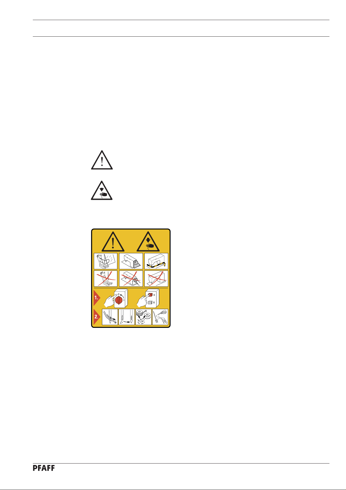
1.03 Safety symbols
Danger!
Special points to observe.
Danger of injury to operating or technical staff!
Safety
Caution
Do not operate without finger guard and safety devices.
Before threading, changing bobbin and needle, cleaning
etc. switch off main switch.
I
1 - 2
Page 6
Bedienungselemente
2 Control elements
2.01 Control device for remaining bobbin thread
Bobbin thread monitor
● When the use of the last amount of
the remaining thread supply begins, the
LED 1 starts flashing.
● When the remaining thread supply has
been used up, the LED 1 lights up
permanently until the bobbin has been
changed.
Bobbin thread counter
● When the thread counter reaches its end,
the LED 1 starts flashing.
● If sewing continues without the bobbin
1
being changed, the LED 1 remains on
permanently until the bobbin is changed.
Fig. 2 - 01
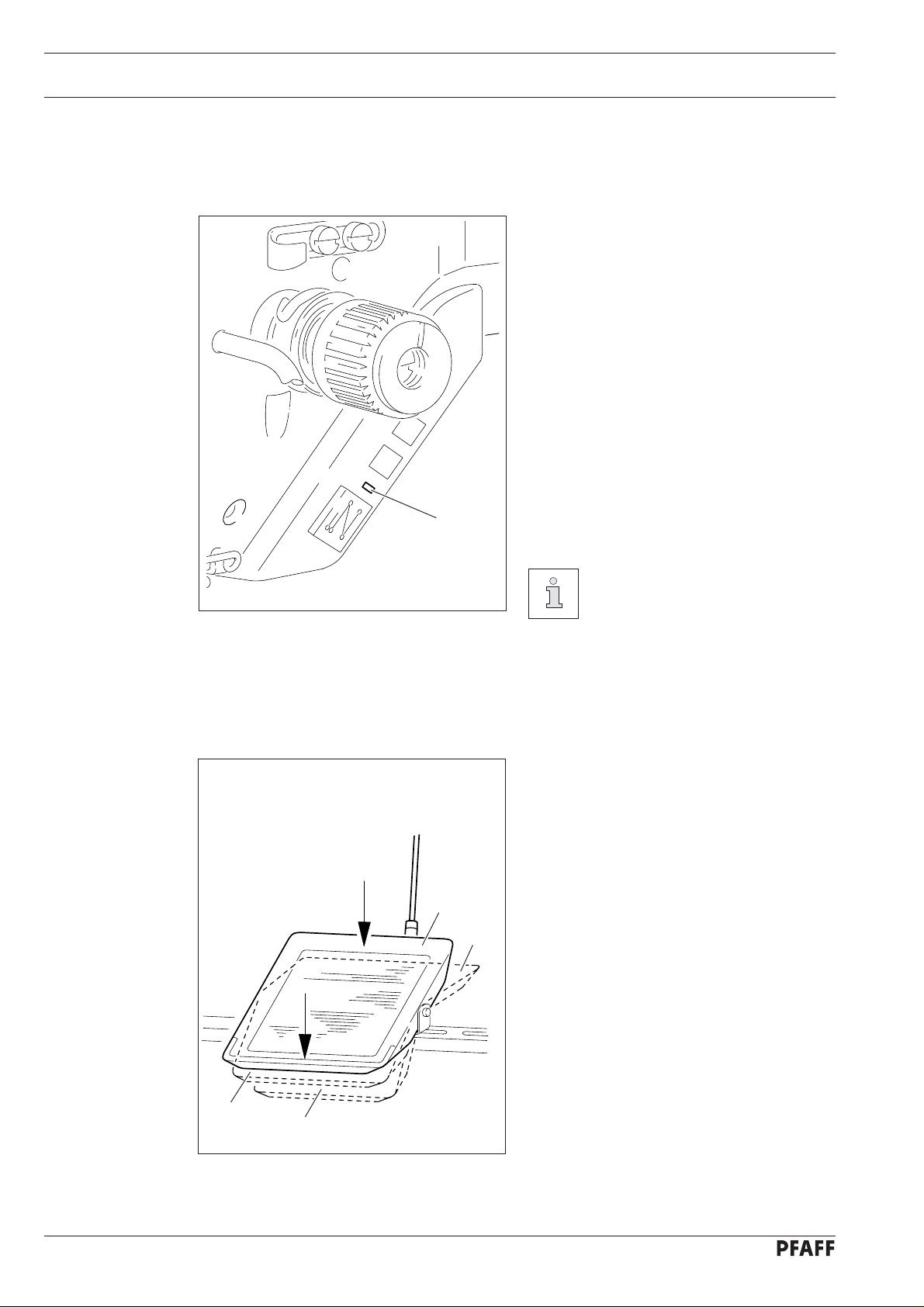
2.02 Pedal
To select thread monitoring or
thread counting see Chapter
5.03 Parameter settings.
0 = Neutral position
1 = Sewing
2 = Raise presser foot
3 = Trim sewing threads / reset
0
+ 1
bobbin thread monitor or bob
bin thread counter
2 - 1
- 1
- 2
Fig. 2 - 02
Page 7

3 Preparation
All regulations and instructions in this Instruction Manual are to be observed!
Special attention is to be paid to the safety regulations!
All preparation work is only to be carried out by appropriately trained personnel.
Before all preparation work, the machine is to be separated from the electricity
supply by removing the plug from the mains or switching off the On/Off switch!
3.01 Winding the bobbin thread, adjusting the thread tension
4
1
-
Preparation
+
81-094
3
1
2
Fig. 3 - 01
● Fit empty bobbin 1 onto bobbin winder spindle 2 with the rest thread chamber on the
outside.
● Thread the thread as shown in the above illustration and wind it round the bobbin 1 a few
times in an anti-clockwise direction.
● Switch on the bobbin winder by pressing bobbin winder spindle 2 and lever 3
simultaneously.
5
6
81-096
81-095
3 - 1
Page 8

Preparation
The bobbin fills up during sewing.
If the machine is only run for bobbin winding (without sewing), a hook
base must be fitted in the hook.
Otherwise a jammed thread may damage the hook!
● The tension of the thread on bobbin 1 can be adjusted with knurled screw 4.
● The bobbin winder stops automatically when bobbin 1 is full.
If the thread is wound unevenly:
● Loosen nut 5.
● Turn thread guide 6 accordingly.
● Tighten nut 5..
3.02 Inserting the bobbin case / Adjusting the bobbin thread tension
2
1
-
-
Fig. 3 - 02
1
+
Fig. 3 - 03
5 cm
3 - 2
● Insert bobbin 1 into the bobbin case 2 as shown in Fig. 3-02.
● Place the bobbin in the bobbin case.
● Pass the thread through the slot under the spring as shown in Fig. 3-03. When the thread
is drawn off, the bobbin must turn in the direction shown by the arrows.
● Adjust the thread tension by turning screw 1.
Page 9

4 Sewing
4.01 Sewing with bobbin thread monitoring
The bobbin thread monitoring function is activated, when parameter "660" is set
at value "1". The number of stitches remaining after the bobbin thread monitor
has reacted is entered under parameter "760". More information about the
parameter setting is contained in Chapter 5.03 Parameter settings.
1
2
Fig. 4 - 01
Sewing
● If the bobbin thread monitor recognises
during sewing that the remaining
amount of thread has been started, LED
1 starts flashing.
Sewing can be continued without changing the bobbin, and from this point on
the pre-set number of remaining stitches
are counted.
● If the number of remaining stitches after
recognition of the bobbin thread monitor
have been sewn, the machine stops
automatically with the needle lowered
and LED 1 remains lit up permanently.
● Set the pedal at its neutral position (pedal
position "0").
● Complete the seam (pedal position "+1").
● Carry out the thread trimming function
(pedal position "-2").
● The bobbin thread monitor is reset.
● Change the bobbin.
The bobbin thread monitor can be reset at any time by pressing key 2 and at
the same time operating the pedal in position "-2".
4 - 1
Page 10

Sewing
4.02 Sewing with remaining bobbin thread count
The remaining bobbin thread count function is activated, when parameter "660"
is set at value "2". The total number of stitches for the bobbin is entered under
parameter "760". More information about the parameter setting is contained in
Chapter 5.03 Parameter settings.
● If the total number of stitches have been
sewn, the machine stops automatically
with the needle lowered and LED 1
flashes.
● If sewing is continued without a bobbin
change, LED 1 remains lit up
permanently.
● Set the pedal at its neutral position (pedal
position "0").
● Complete the seam (pedal position "+1").
● Carry out the thread trimming function
(pedal position "-2").
1
The bobbin thread monitor is reset.
● Change the bobbin.
Fig. 4 - 02
2
The bobbin thread monitor can be reset at any time by pressing key 2 and at
the same time operating the pedal in position "-2".
4 - 2
Page 11

Adjustment
5 Adjustment
5.01 Notes on adjustment
All adjustments in this instruction manual apply to a completely assembled machine and may
only be carried out by suitably trained staff.
Machines covers which are removed for control and adjustment work and then set back in
place again are not mentioned in the text.
5.02 Function control and adjustment of the bobbin thread monitor
Requirement
The value of parameter "382" should correspond to the average value of the top and
bottom threshold value of the thread monitor.
● Insert a full bobbin in the bobbin case and place the bobbin case in the hook.
No / VAL
● Switch on the machine.
● Press the TE/Speed key to call up the parameter input function.
TE
No VAL
A 101 ON
● By pressing the corresponding +/- keys, set parameter "798" at value "1" (selecting the
mechanic level).
TE
No VAL
B 798 1
No / VAL
● By pressing the corresponding +/- keys, set parameter "797" at "ON" (displaying the
inputs).
TE
No VAL
B 797 ON
5 - 1
Page 12

Adjustment
E 1 X 5: 5 0
● By pressing the corresponding +/- keys, select sub-menu "Fw" (thread monitor menu).
Fw 63%
● Draw the bobbin thread by hand and note the top or bottom threshold value
(e.g. 63% or 3% => average value: 30%)
No / VAL
● Press the TE/Speed key to call up the parameter input function.
● By pressing the corresponding +/- keys, select parameter "382" and enter the
corresponding average value (e.g. "30").
TE
No VAL
B 382 30
● Press the TE/Speed key to conclude the parameter input function.
● Switch off the machine.
5 - 2
Page 13

5.03 Parameter settings
5.03.01 Selecting and altering parameters
● Switch on the machine.
● Press the TE/Speed key to call up the parameter input function.
TE
No VAL
A 101 ON
No
● By pressing the corresponding +/- keys, select the desired parameter group, e.g. "600".
Adjustment
TE
No
600
● By pressing the corresponding +/- keys, select the desired parameter, e.g. "660" for the
No
bobbin thread monitoring function.
TE
No VAL
A 660 1
● By pressing the corresponding +/- keys, set the desired value for the selected parameter,
VAL
e.g. "2" for the "bobbin rest thread counter on" function.
TE
No VAL
A 660 2
● By pressing the TE/Speed key the value is taken over and the machine changes to the
sewing mode.
5 - 3
Page 14

Adjustment
5.03.02 Selecting the user level
No
● Switch on the machine.
● Press the TE/Speed key to call up the parameter input function.
TE
No VAL
A 101 ON
● By pressing the corresponding +/- keys, select the parameter group "700".
TE
No
700
● By pressing the corresponding +/- keys, select parameter "798".
No
TE
No VAL
A 798 0
● By pressing the corresponding +/- keys, select the desired user level:
VAL
"0" = operator lever A
"1" = mechanic level B
"11" = service level C
● By pressing the TE/Speed key the value is taken over and the machine changes to the
sewing mode.
5 - 4
Page 15

5.03.03 List of parameters
Adjustment
Parameter
Group
3 382 Average value for switching threshold B 0 – 100 15
6 660 Bobbin thread monitor A 0 – 2 0
7 760 Number of stitches A 0 – 250 5
797 Hardware test C ON-OFF OFF
798 User level A 0 – 255 0
Description
bobbin thread monitor
0 = off
1 = bobbin thread monitor on
2 = bobbin thread reverse counter on
for remaining thread after reaction of
bobbin thread monitor
(for bobbin thread monitoring)
No. of stitches (x 200)
(for remaining bobbin thread count)
0 = operator level A
1 = mechanic level B
11 = service level C
Access level
Adjustment
range
Standard value
The standard values listed in the table are basic settings. When required,
deviations are possible.
5 - 5
Page 16

Pa rts list
95-774 460-91
11-130 092-25
12-305 084-25
91-056 193-25
91-174 879-05
91-056 192-25
12-024 191-25
95-774 459-25
11-330 952-15
40/13
99-137 151-45
91-266 397-01
91-118 683-05
12-640 130-55
95-774 465-25
95-774 467-05
95-774 466-91
91-118 685-05
91-118 940-05
14-602 90 1-01 (2x)
91-171 049-05
91-100 281-25
91-171 042-05
95-774 464-25
91-700 996-15
6 - 1
91-174 783-05
11-250 084-25
Page 17

95-774 525-91 (PFAFF 1051;1181)
11-210 084-25 (2x)
Pa rts list
95-784 334-91
95-774 409-25
91-004 181-05
91-100 076-15 (2x)
95-774 408-91
95-774 524-91 (PFAFF 1053;1183)
11-210 084-25 (2x)
95-774 419-25
91-262 806-05
91-000 621-15 (2x)
95-774 407-91
95-784 334-91
95-774 361-05
6 - 2
Page 18

 Loading...