

Page 1

TECHNICAL TRAINING
SALES DIVISION
PRESENTATION OF THE
MACHINE
réf :.JET.010.02/2003.GB
Page 2

Page 3

CONTENTS
TRAINING MANUAL: JET FORCE: Page : 3/43
Reproduction or translation, even partial, is forbidden without the written consent of Peugeot Motocycles
CHARACTERISTICS ................................................................................................................................ 5
Engine ......................................................................................................................................................... 5
Dimensions and weight .............................................................................................................................. 5
50 CC ENGINES.......................................................................................................................................... 6
50 cc 2-stroke TSDI liquid cooled engine .................................................................................................. 6
Description ................................................................................................................................................. 7
Separate lubrication .................................................................................................................................... 7
Cooling ....................................................................................................................................................... 7
CATALYTIC EXHAUST ........................................................................................................................... 8
Composition of the catalytic exhaust system: ............................................................................................ 8
FUNCTIONING OF THE CATALYTIC CONVERTER EXHAUST................................................... 8
Definition .................................................................................................................................................... 8
INJECTION SYSTEMS / TSDI IGNITION ............................................................................................. 9
Introduction ................................................................................................................................................ 9
SYSTEM COMPONENTS ....................................................................................................................... 10
Functioning principle ............................................................................................................................... 10
PRESENTATION OF THE 2 STROKE INJECTION SYSTEM ........................................................ 11
DIAGNOSTIC............................................................................................................................................ 12
Warning .................................................................................................................................................... 12
Fault processing principle ........................................................................................................................ 12
Self-diagnostic principle ........................................................................................................................... 12
125 CC ENGINES...................................................................................................................................... 13
125 cc 4-stroke EFI liquid cooled engine ................................................................................................. 13
Description ............................................................................................................................................... 14
Lubrication ............................................................................................................................................... 14
Cooling ..................................................................................................................................................... 14
Cooling system functioning principle ...................................................................................................... 14
INTRODUCTION ..................................................................................................................................... 15
ADVANTAGES OF THE INJECTION SYSTEM ................................................................................. 15
Fuel injector .............................................................................................................................................. 15
INJECTION SYSTEM / EFI IGNITION................................................................................................ 16
Reminder of operation .............................................................................................................................. 16
FRAME ....................................................................................................................................................... 17
Frame ........................................................................................................................................................ 17
Suspension ................................................................................................................................................ 18
Tyres ......................................................................................................................................................... 18
Suspension ................................................................................................................................................ 19
Tyres ......................................................................................................................................................... 19
BRAKES ..................................................................................................................................................... 20
Reminder of functioning of the different braking systems ....................................................................... 20
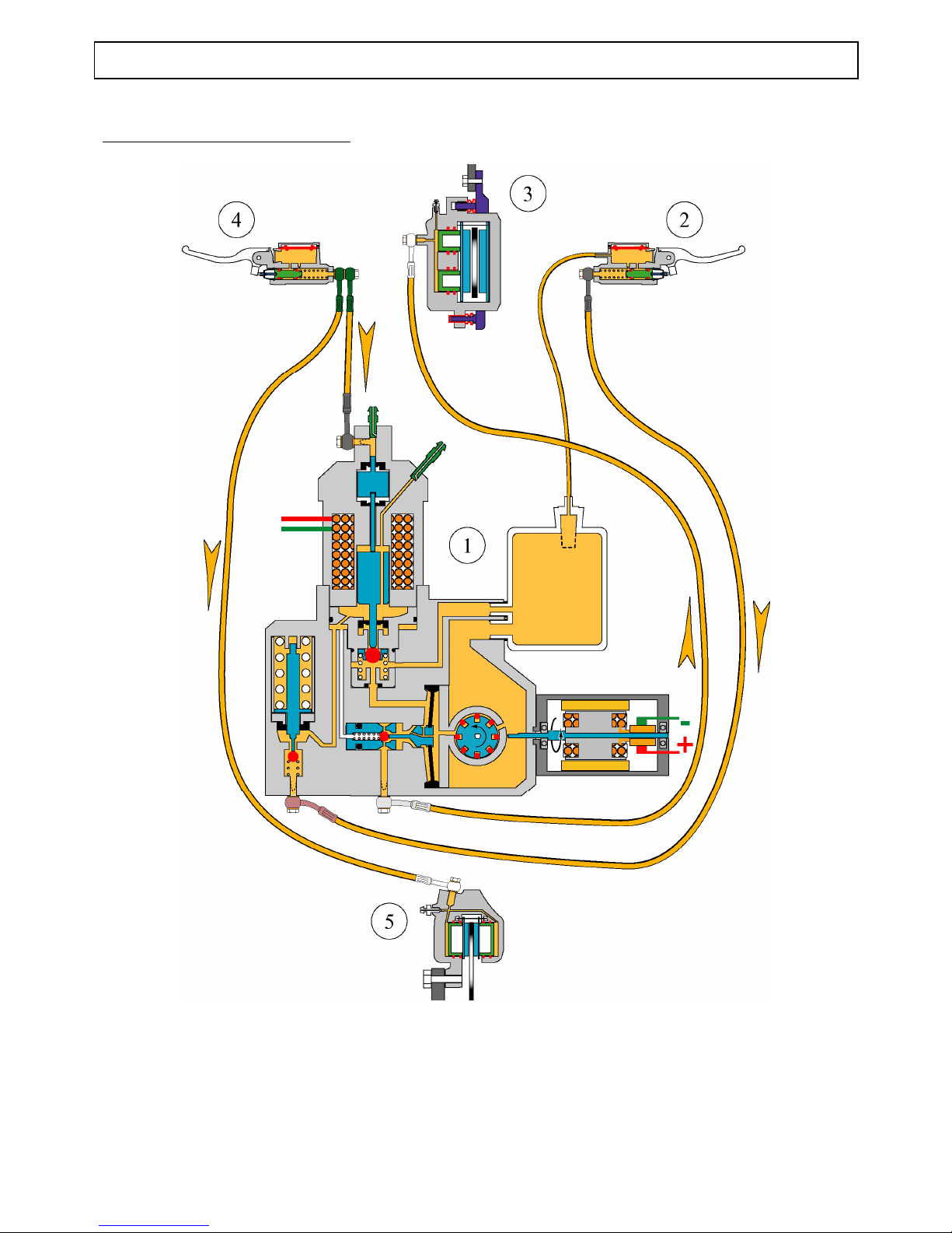
ABS/PBS hydraulic braking system......................................................................................................... 21
ABS/PBS SYSTEM SYNOPTICS ............................................................................................................ 22
BODY PANELS ......................................................................................................................................... 23
ELECTRICITY ......................................................................................................................................... 25
Functioning principle of the 50 cc starter and lighting circuits ................................................................ 25
50 cc ignition on or engine running .......................................................................................................... 26
50 cc starting function .............................................................................................................................. 27
Direction indicator functioning principle (125 cc) ................................................................................... 28
Hazard warning lights with ignition on (125 cc) ...................................................................................... 29
Page 4

CONTENTS
TRAINING MANUAL: JET FORCE: Page : 4/43
Reproduction or translation, even partial, is forbidden without the written consent of Peugeot Motocycles
Hazard warning lights without ignition on (125 cc) ................................................................................. 30
Functioning principle of the ABS/PBS system (125 cc) .......................................................................... 31
ABS/PBS ELYSTAR 125cc .................................................................................................................... 32
TRANSPONDER IMMOBILISER ......................................................................................................... 33
System programming ............................................................................................................................... 33
Reminder of the key memory procedure .................................................................................................. 33
Key memory check ................................................................................................................................... 33
Additional information ............................................................................................................................. 33
Synoptics .................................................................................................................................................. 34
INSTRUMENT CLUSTER ...................................................................................................................... 36
Description ............................................................................................................................................... 36
Instrument cluster self-diagnostic when ignition is turned on ................................................................. 36
Description of the multi-function display ................................................................................................ 37
MULTI-FUNCTION DISPLAY FUNCTIONS AND SETTINGS ....................................................... 37
Changing the distance unit ....................................................................................................................... 37
Tripmeter Total/Daily display .................................................................................................................. 38
Daily Km reset .......................................................................................................................................... 38
Time setting .............................................................................................................................................. 38
Maintenance reset ..................................................................................................................................... 39
Fuel gauge self-diagnostic ........................................................................................................................ 39
Gauge functioning (8s timer) ................................................................................................................... 39
LOCATION OF COMPONENTS ........................................................................................................... 40
50 cc ......................................................................................................................................................... 40
125 cc ....................................................................................................................................................... 41
SPECIAL TOOLING ................................................................................................................................ 42
Page 5
CHARACTERISTICS
TRAINING MANUAL: JET FORCE: Page : 5/43
Reproduction or translation, even partial, is forbidden without the written consent of Peugeot Motocycles
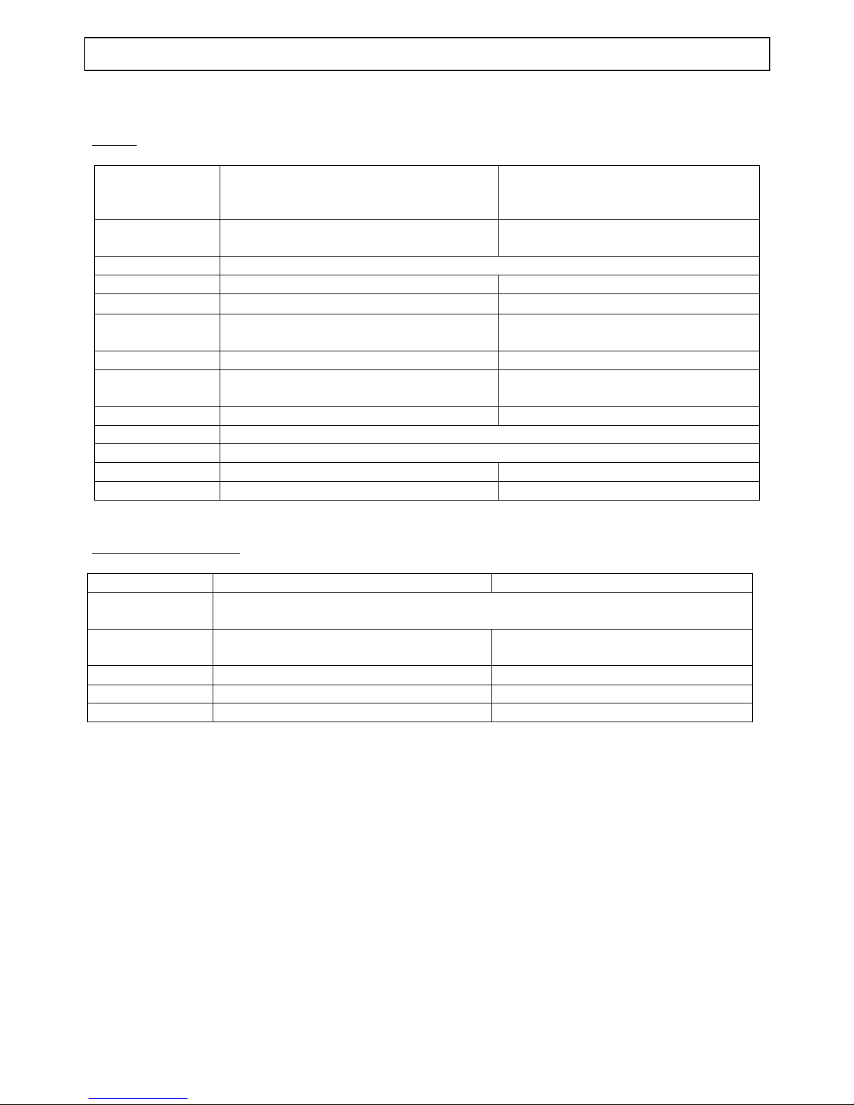
CHARACTERISTICS
Engine
50 cm3 125 cm3
Type Single cylinder 2-stroke direct injection
Single cylinder 4-stroke indirect
injection
Cooling Liquid
Bore x stroke 39.9 x 39.8 mm 57 x 48.9 mm
Cubic capacity 49.9 cc 124.8 cc
Max. power
output
3.75 kW at 7500 rpm 9.2 kW at 8750 rpm
Max. torque at 6500 rpm 7250 rpm
Fuel system
Direct electronic injection
(TSDI)
Indirect electronic injection (EFI)
Lubrication Electric oil pump Trochoidal pump
Transmission 2 variable pulleys and Vee belt
Clutch Centrifugal automatic
Spark plug NGK CPR8E NGK CR7EB
Exhaust Catalytic Non-catalytic
Dimensions and weight
Overall length 1914 mm 1918 mm
Width at
handlebar
740 mm
Height with rear
view mirror
1260 1279
Wheelbase 1314 mm 1369 mm
Saddle height: 820 mm 845 mm
Unladen weight 115 kg 149 kg
Page 6

50 CC ENGINES
TRAINING MANUAL: JET FORCE: Page : 6/43
Reproduction or translation, even partial, is forbidden without the written consent of Peugeot Motocycles
50 CC ENGINES
50 cc 2-stroke TSDI liquid cooled engine
45 km/h version
Sport version
Unlimited version (registered)
Page 7
50 CC ENGINES
TRAINING MANUAL: JET FORCE: Page : 7/43
Reproduction or translation, even partial, is forbidden without the written consent of Peugeot Motocycles
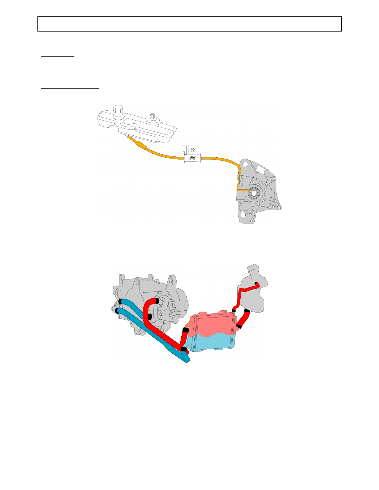
Description
HL1 engine marking
Separate lubrication
1.2 l tank capacity
Cooling
1.2 l capacity
Page 8

CATALYTIC EXHAUST
TRAINING MANUAL: JET FORCE: Page : 8/43
Reproduction or translation, even partial, is forbidden without the written consent of Peugeot Motocycles
CATALYTIC EXHAUST
Composition of the catalytic exhaust system:
The catalytic exhaust system is distinguished by the fitting of a « catalyser cone » just after the exhaust
inlet cone. All the exhaust gases are fed through the catalyser cone.
1. Exhaust pipe
2. Heat insulation
3. Catalyser cone
FUNCTIONING OF THE CATALYTIC CONVERTER EXHAUST
Definition
The catalyser is a block used to facilitate and acceleration chemical reactions without being modified
itself
Composition of the catalytic block
The catalytic block is composed of a metal grid, impregnated with precious metals, rolled inside a steel
tube forming a honeycomb.
1. Metal grid
2. Steel tube
3. Honeycomb
4. Impregnation with precious metals (Platinum, palladium, rhodium, etc...)
Page 9
INJECTION SYSTEMS / TSDI IGNITION
TRAINING MANUAL: JET FORCE: Page : 9/43
Reproduction or translation, even partial, is forbidden without the written consent of Peugeot Motocycles
INJECTION SYSTEMS / TSDI IGNITION
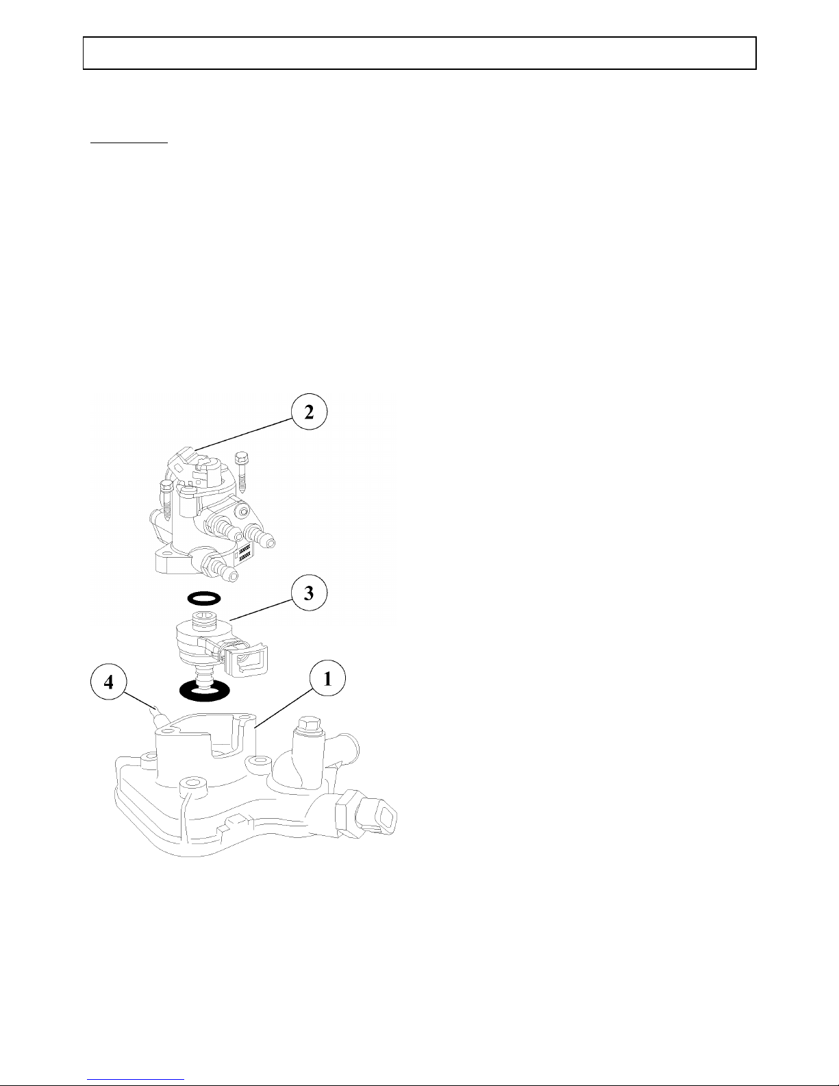
Introduction
Of the throttle angle / engine speed type, the SYNERJECT system was developed for the following
applications:
Monopoint sequential injection
Static timing
The system basic principle consists in measuring the engine speed and load ( throttle opening ) in order to
determine the optimum quantity of fuel injected
This system is used on the JET FORCE 50 scooter and requires NO ADJUSTMENT
(Ditto Looxor and Elystar 50 cc).
1. Cylinder head
2. Petrol injector
3. Air injector
4. Spark plug
Page 10

SYSTEM COMPONENTS
TRAINING MANUAL: JET FORCE: Page : 10/43
Reproduction or translation, even partial, is forbidden without the written consent of Peugeot Motocycles
SYSTEM COMPONENTS
Functioning principle
1. Crank assembly
2. Compressor
3. Throttle unit
4. Spark plug
5. Lubrication system
6. Feed rail
a / petrol injector
b / air injector
c/ petrol pressure regulator
A. Fuel inlet
B. Fuel return
C. Pressurised air inlet
Page 11
PRESENTATION OF THE 2-STROKE INJECTION SYSTEM
TRAINING MANUAL: JET FORCE: Page : 11/43
Reproduction or translation, even partial, is forbidden without the written consent of Peugeot Motocycles
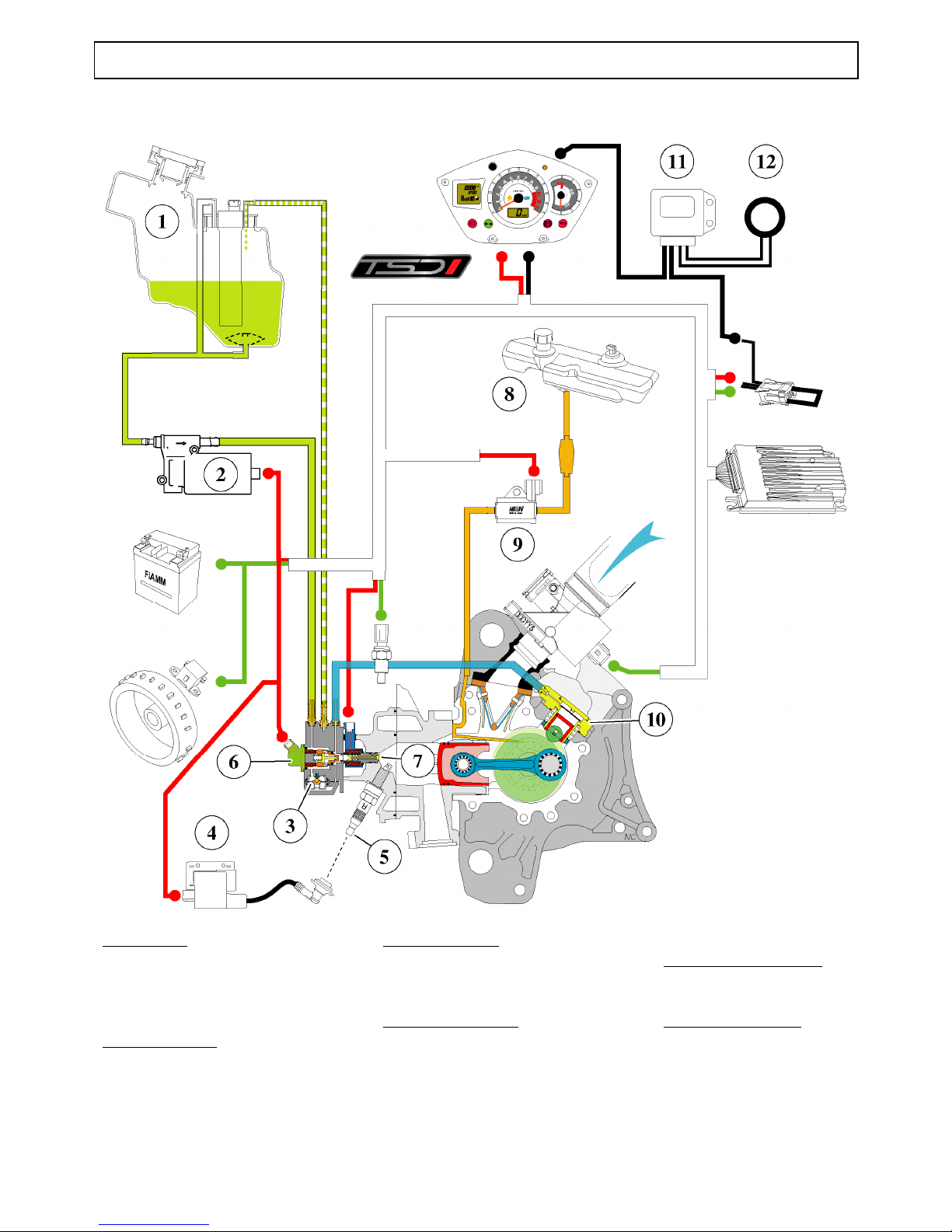
PRESENTATION OF THE 2 STROKE INJECTION SYSTEM
Fuel system
1. Fuel tank
2. Fuel pump
3. Pressure regulator
Ignition system:
4. Coil and suppressor
5. Resistive spark plug
Injection system
6. Petrol injector
7. Air injector
Lubrication system
8. Oil tank
9. Oil pump
Compressed air circuit
10. Compressor
Transponder circuit
11. Immobiliser module
12. Transponder
Page 12
DIAGNOSTIC
TRAINING MANUAL: JET FORCE: Page : 12/43
Reproduction or translation, even partial, is forbidden without the written consent of Peugeot Motocycles
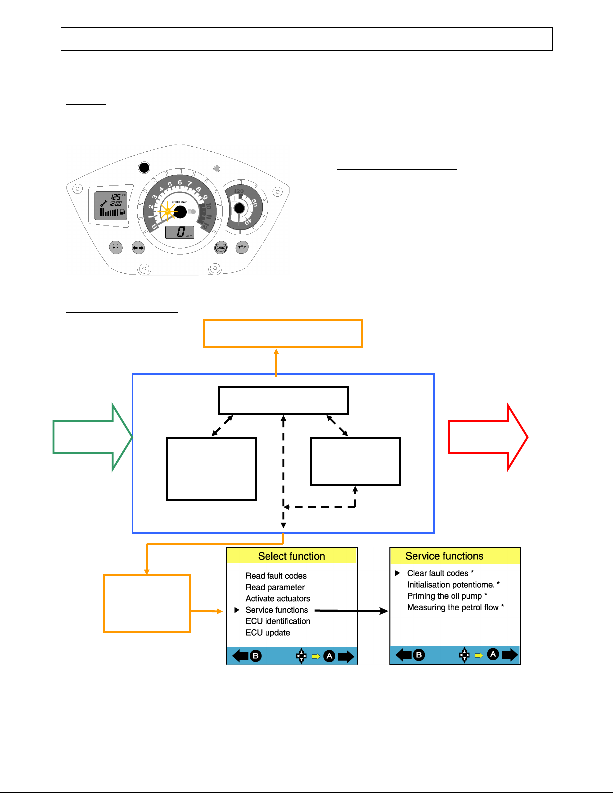
DIAGNOSTIC
Warning
A LED comes on on the instrument
cluster to warn the rider of a fault on the
injection and ignition system ELECTRICS
Fault processing principle
Three priority levels
1 - “ serious safety ” fault: fault
memorised in ECU and LED stays on
2 - “ serious ” fault: fault memorised in
ECU and LED flashes
3 - “ minor ” fault: fault memorised in the
ECU without lighting the warning light
Note: When the ignition is turned on, the
LED stays on to check it is functioning
correctly
Self-diagnostic principle
Warning light on inst. cluster
Injection
ECU
INPUTS OUTPUTS
Dialogue
with the
tester
Microprocessor
Injection
Ignition
System
Fault
memory
Page 13

125 CC ENGINES
TRAINING MANUAL: JET FORCE: Page : 13/43
Reproduction or translation, even partial, is forbidden without the written consent of Peugeot Motocycles
125 CC ENGINES
125 cc 4-stroke EFI liquid cooled engine
Naturally aspirated version
Turbo version (compressor)
Page 14
125 CC ENGINES
TRAINING MANUAL: JET FORCE: Page : 14/43
Reproduction or translation, even partial, is forbidden without the written consent of Peugeot Motocycles
Description
FD5 engine markings
Lubrication
1.25 l capacity
Cooling
1.5 l capacity
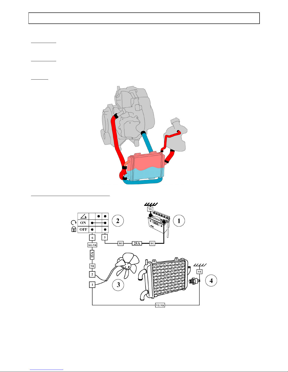
Cooling system functioning principle
1. Battery
2. Ignition switch
3. Fan
4. Heat switch
Page 15
125 CC ENGINES
TRAINING MANUAL: JET FORCE: Page : 15/43
Reproduction or translation, even partial, is forbidden without the written consent of Peugeot Motocycles
INTRODUCTION
Of the throttle angle / engine speed type, the EFI system was developed for the following applications:
Monopoint sequential injection
Static timing
The system basic principle consists in measuring the engine speed and load ( throttle opening ) in order to
determine the optimum quantity of fuel injected
This system is used on the JET FORCE 125 scooter and requires NO ADJUSTMENT
(Ditto Elystar 125 – 150 cc)
ADVANTAGES OF THE INJECTION SYSTEM
Peugeot Motocycles has developed a new generation of engines. Cleaner, more reliable, more
economical, these engines comply with the most stringent emission control standards, whilst
maintaining a very high level of performance. There are many advantages :
- Reduction in polluting emissions
- Reduction in fuel consumption
- Improved rider comfort
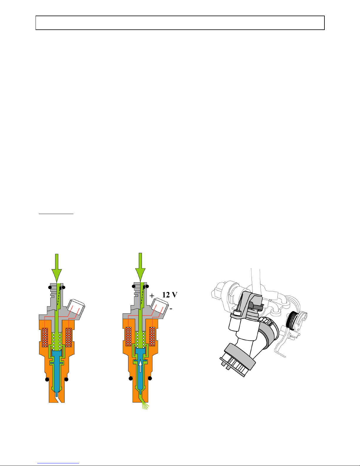
Fuel injector
The injectors are of the electro-magnetically operated single-jet type
The ECU electrical pulses generate a magnetic field in the magnet winding, the core is attracted, the
injector plate raised off its seat and releases the pressurised fuel upline of the inlet valve
Page 16
INJECTION SYSTEM / EFI IGNITION
TRAINING MANUAL: JET FORCE: Page : 16/43
Reproduction or translation, even partial, is forbidden without the written consent of Peugeot Motocycles
INJECTION SYSTEM / EFI IGNITION
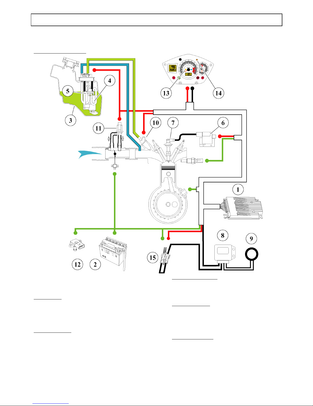
Reminder of operation
1. ECU
2. Battery
Fuel system
3. Fuel tank
4. Fuel pump
5. Pressure regulator
Ignition system:
6. HT coil
7. Resistive spark plug and suppressor
Transponder circuit
8. Transponder module
9. Transponder
Injection system
10. Petrol injector
11. Idle control valve
12. Air pressure and air temperature sensor
Diagnostic circuit
13. Injection diagnostic lamp
14. Transponder diagnostic lamp
15. Diagnostic plug
Page 17
FRAME
TRAINING MANUAL: JET FORCE: Page : 17/43
Reproduction or translation, even partial, is forbidden without the written consent of Peugeot Motocycles
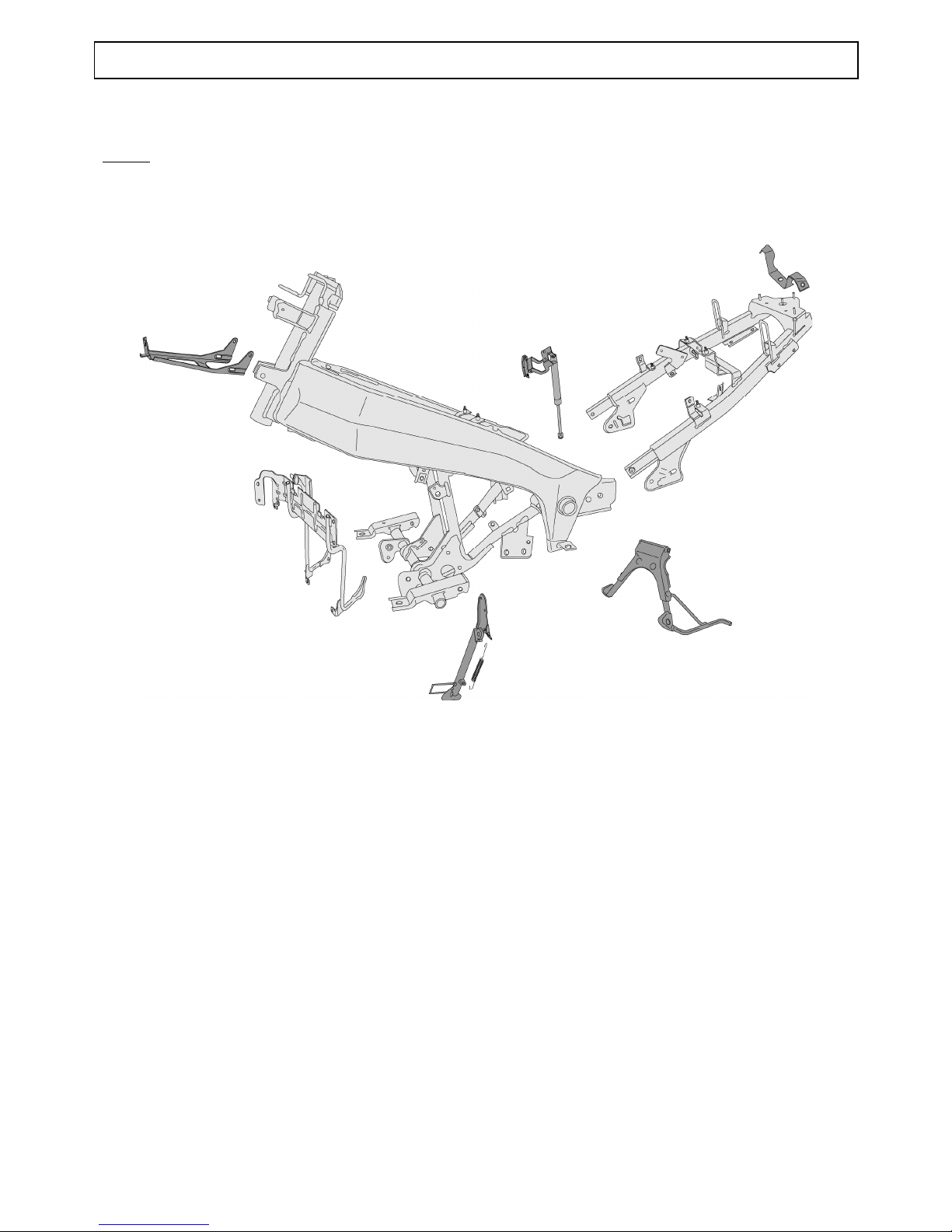
FRAME
Frame
Steel wrap-round frame (DIRECT PERIMETRIC FRAME - DPF)
Page 18
50 CC FRAME
TRAINING MANUAL: JET FORCE: Page : 18/43
Reproduction or translation, even partial, is forbidden without the written consent of Peugeot Motocycles
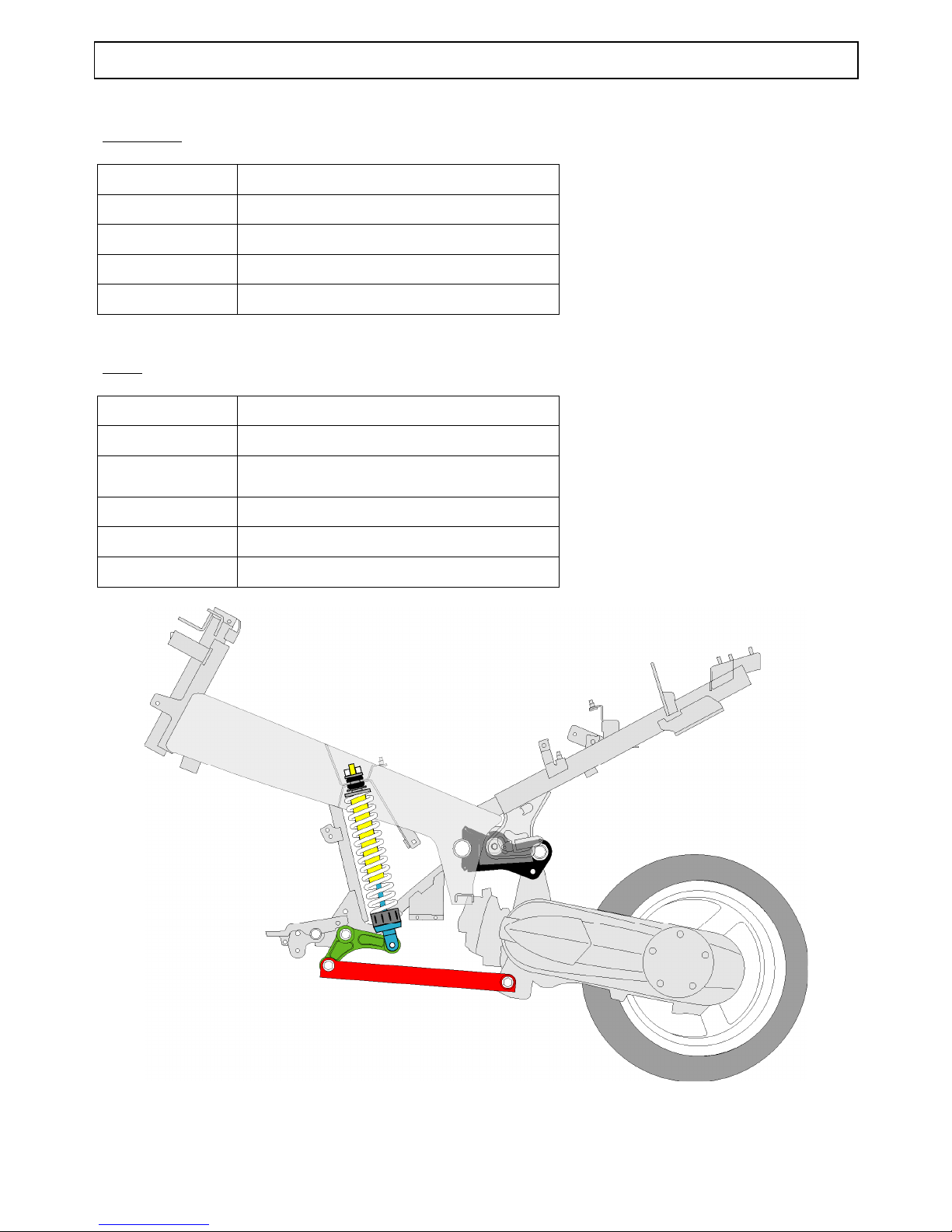
Suspension
50 cm3
Front suspension:
Ø 32 mm hydraulic telescopic fork
Travel 85 mm
Rear suspension Central hydraulic shock absorber
Travel 95 mm
Tyres
Front wheel 13-inch alloy
Front tyre 130/60 - 13
Front tyre
pressure
2 bar
Rear wheel 13-inch alloy
Rear tyre 130/60 - 13
Rear tyre pressure
2,2 bar
Page 19
125 CC FRAME
TRAINING MANUAL: JET FORCE: Page : 19/43
Reproduction or translation, even partial, is forbidden without the written consent of Peugeot Motocycles
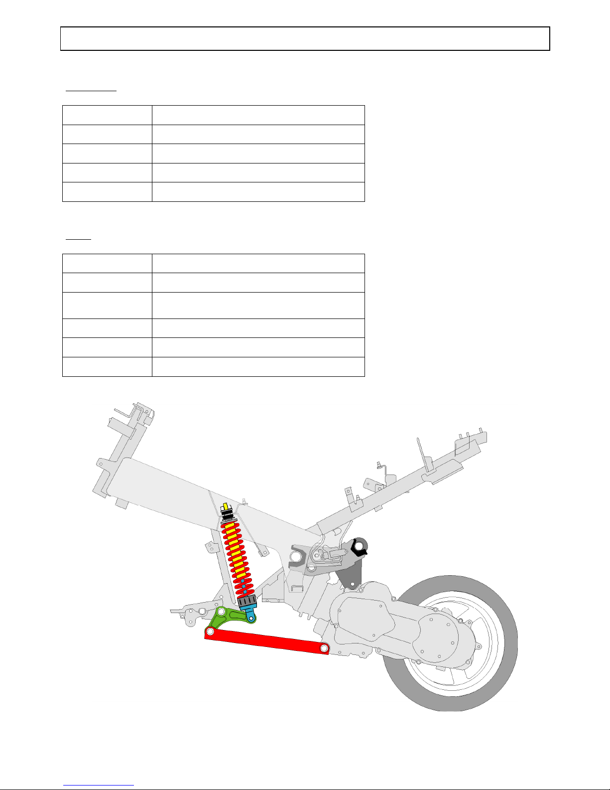
Suspension
125 cm3
Front suspension Ø 36 mm hydraulic telescopic fork
Travel 95 mm
Rear suspension Central hydraulic shock absorber
Travel 90 mm
Tyres
Front wheel 13-inch alloy
Front tyre 130/60 - 13
Front tyre
pressure
2 bar
Rear wheel 13-inch alloy
Rear tyre 140/60 - 13
Rear tyre pressure
2,2 bar
Page 20
BRAKES
TRAINING MANUAL: JET FORCE: Page : 20/43
Reproduction or translation, even partial, is forbidden without the written consent of Peugeot Motocycles
BRAKES
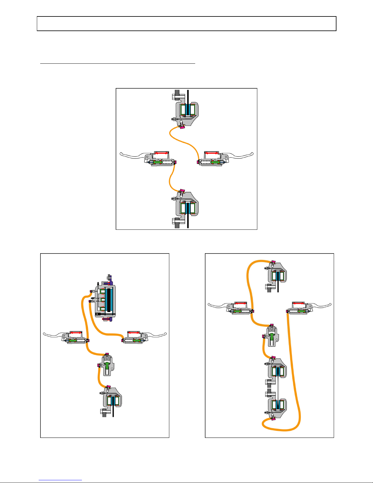
Reminder of functioning of the different braking systems
Conventional hydraulic system
SBC integral hydraulic braking system
SBC2 integral hydraulic braking system
Page 21
BRAKES
TRAINING MANUAL: JET FORCE: Page : 21/43
Reproduction or translation, even partial, is forbidden without the written consent of Peugeot Motocycles
ABS/PBS hydraulic braking system
1. Braking control unit
2. Right-hand brake master cylinder (emergency brake)
3. Front brake caliper
4. Left-hand brake master cylinder (integral brake)
5. Rear brake caliper
Page 22
ABS/PBS SYSTEM SYNOPTICS
TRAINING MANUAL: JET FORCE: Page : 22/43
Reproduction or translation, even partial, is forbidden without the written consent of Peugeot Motocycles
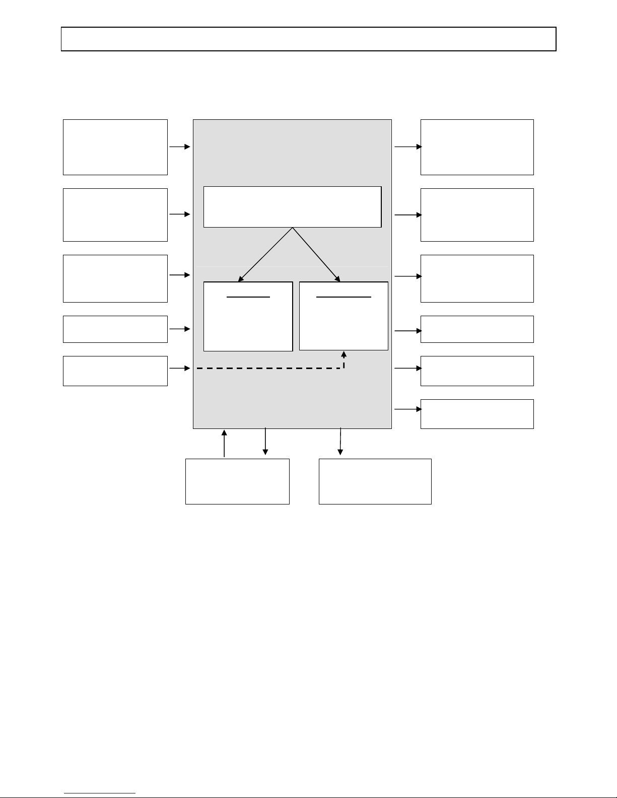
ABS/PBS SYSTEM SYNOPTICS
RH brake lever
contactor
Hydraulic pump
RH brake lever
contactor
Brake light
Front wheel speed
sensor
Regulation solenoid
valve
Battery voltage
Main relay
Vehicle coding
(PIN code)
Starter relay
Instrument cluster
Diagnostic plug
Diagnostic light
Software:
Manages system
operation
Calibration:
Values specific
to machine
(mapping)
ABS/PBS
ECU
Page 23
BODY PANELS
TRAINING MANUAL: JET FORCE Page : 23/43
Reproduction or translation, even partial, is forbidden without the written consent of Peugeot Motocycles
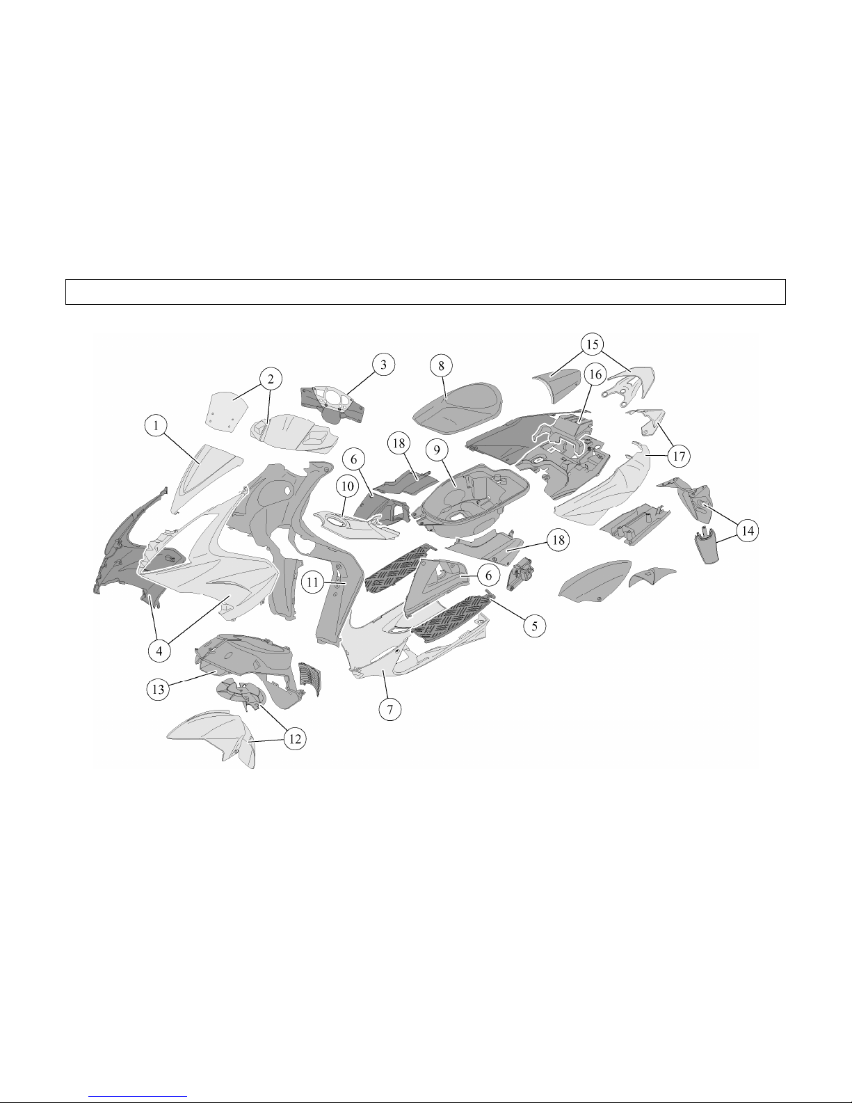
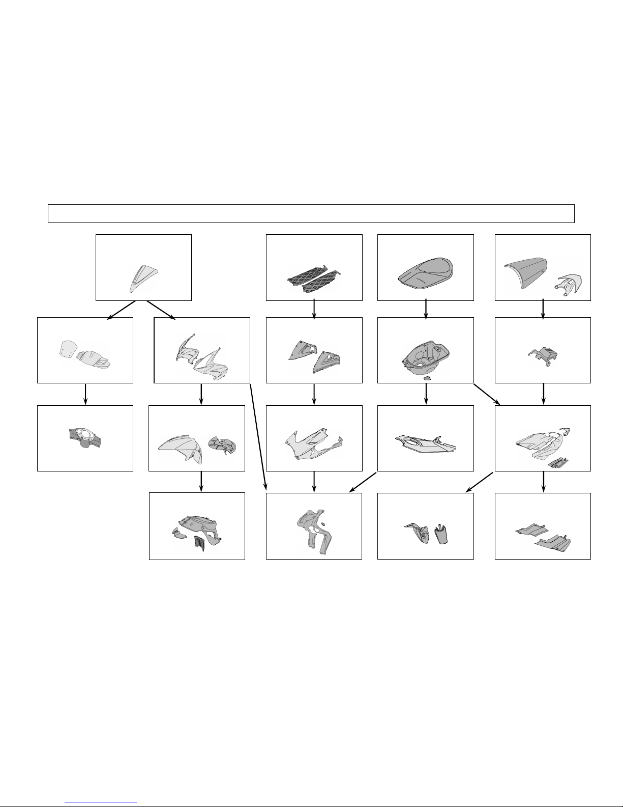
BODY PANELS
Page 24
BODY PANELS
TRAINING MANUAL: JET FORCE Page : 24/43
Reproduction or translation, even partial, is forbidden without the written consent of Peugeot Motocycles
HANDLBAR FRONT FAIRING
(2)
FRONT LOWER LEGSHIELDS
(4)
LEGSHIELD REAR PANEL
(11)
MUDGUARD AND FORK
GUARD
(12)
FOOTBOARDS
(5)
TUNNELS
(6)
FUEL TANK FAIRING
(10)
RIDER SADDLE
(8)
PASSENGER SADDLE AND
GRAB HANDLE
(15)
REAR FAIRING AND
IMMOBILISER UNIT (17)
STORAGE COMPARTMENT
(9)
STORAGE COMPARTMENT
TRIM PANELS
(18)
HANDLEBAR REAR FAIRING
(3)
BATTERY COVER
(16)
MUDGUARD
(13)
BELLYPAN
(7)
MUDFLAP AND NUMBER
PLATE PANEL
(14)
LEGSHIELD TOP PANEL
(1)
Page 25
ELECTRICITY
TRAINING MANUAL: JET FORCE Page : 25/43
Reproduction or translation, even partial, is forbidden without the written consent of Peugeot Motocycles
ELECTRICITY
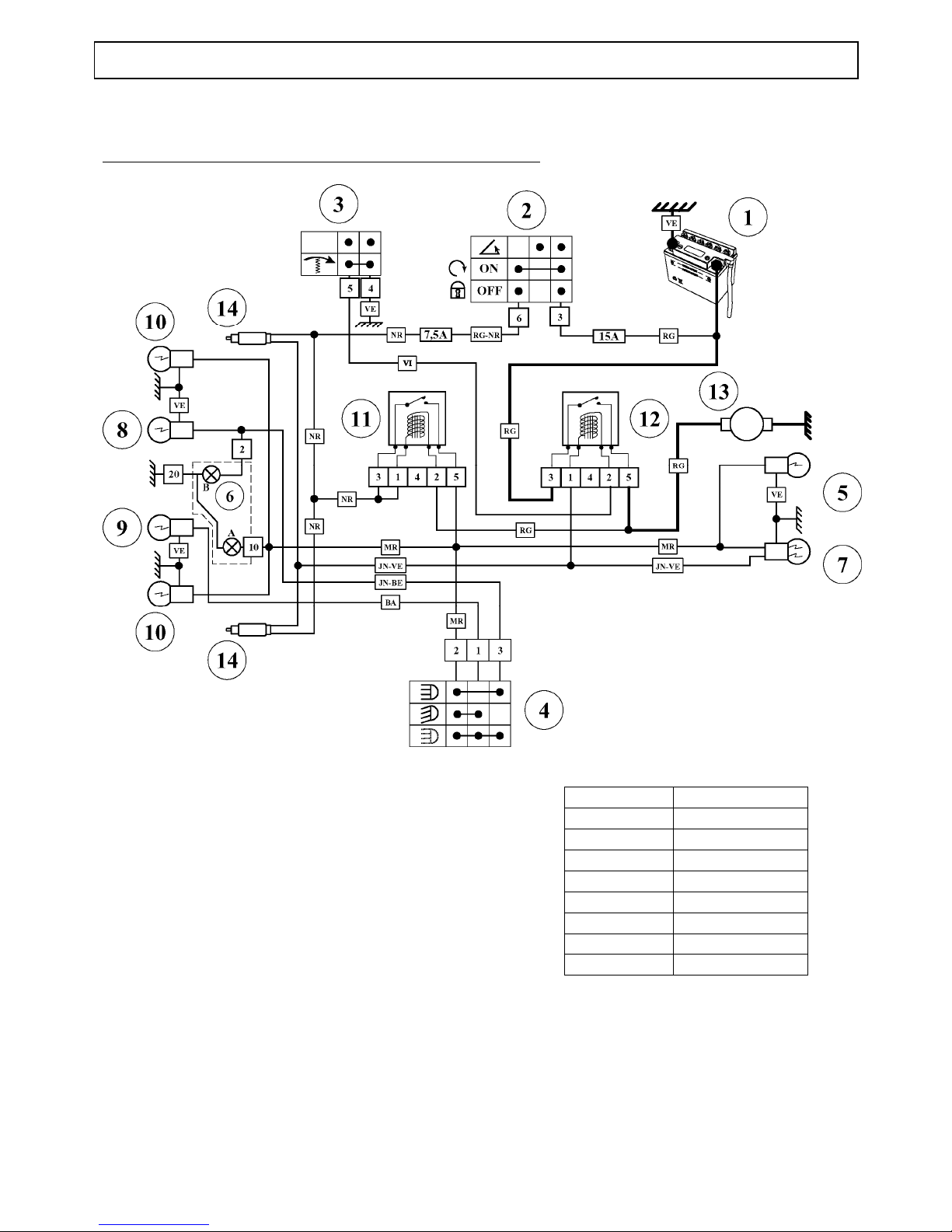
Functioning principle of the 50 cc starter and lighting circuits
1. Battery
2. Ignition switch
3. Starter button
4. Lighting control
5. Rear light
6. Instrument cluster
7. Brake light
8. High beam
9. Dip beam
10. Sidelight
11. Lighting relay
12. Starter motor relay
13. Starter motor
14. Brake light switch
BA White
JN-BE Yellow-Blue
JN-VE Yellow-Green
MR Brown
NR Black
RG Red
RG-NR Red-Black
VE Green
VI Mauve
Page 26
ELECTRICITY
TRAINING MANUAL: JET FORCE Page : 26/43
Reproduction or translation, even partial, is forbidden without the written consent of Peugeot Motocycles
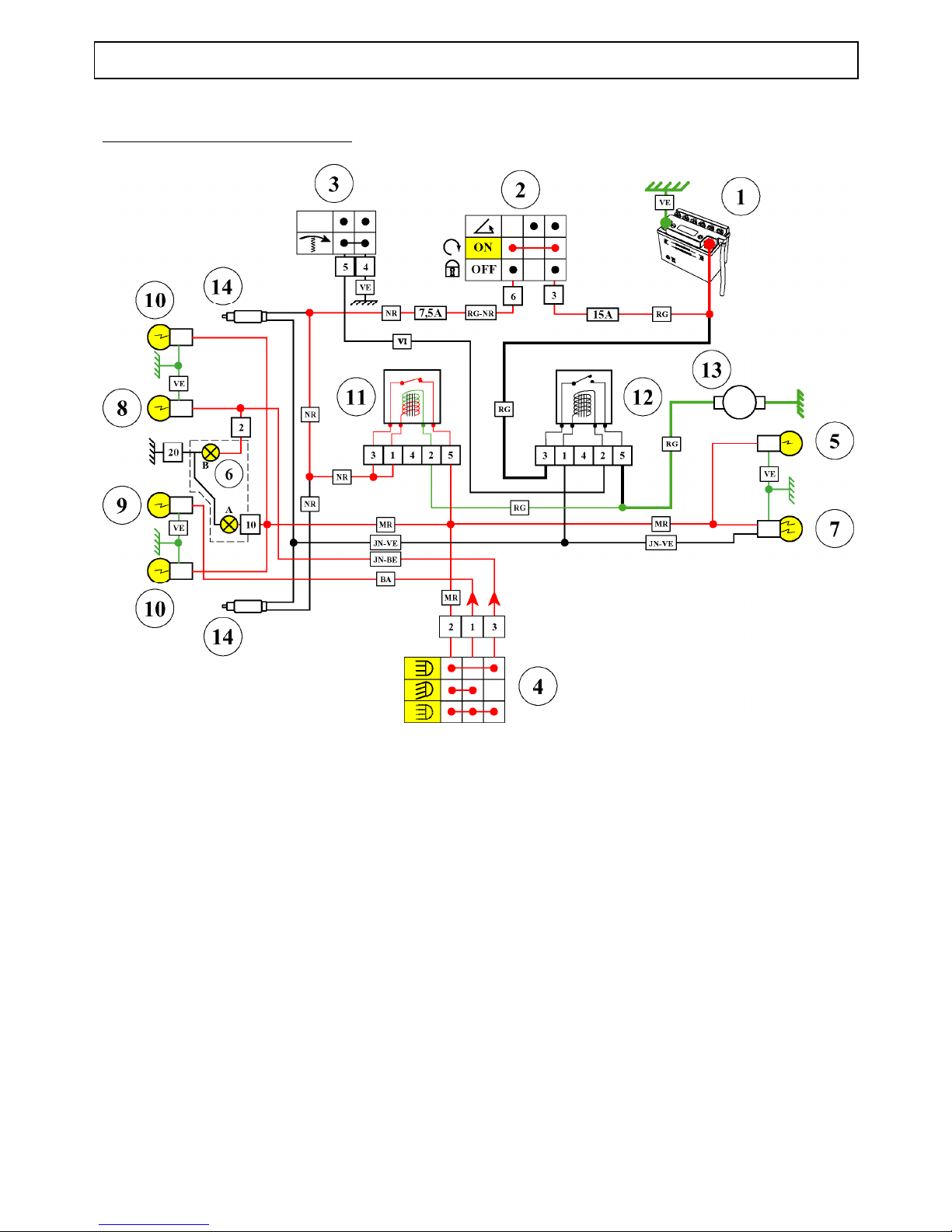
50 cc ignition on or engine running
The lighting relay (11) is powered when the ignition is on via terminals 1 and 3
Over terminal 2 of the relay, the control coil is earthed through the starter motor (13)
The power circuit, via relay terminal 5 powers:
- The rear and front sidelights
- The number plate light (50cc IL and 125cc)
- The instrument cluster lighting
- Power supply to the Dip/Full Beam control (4) and the headlight flasher for the 125 cc
Page 27
ELECTRICITY
TRAINING MANUAL: JET FORCE Page : 27/43
Reproduction or translation, even partial, is forbidden without the written consent of Peugeot Motocycles
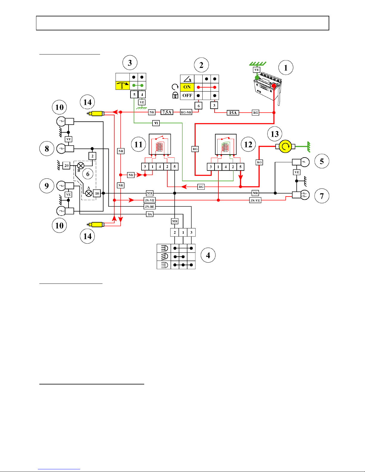
50 cc starting function
Press starter button (3):
Pressing the starter button (3) earths the starter relay winding (12) which then powers:
- The starter motor
- Terminal 2 of the lighting relay (11)
The potential on the coil two terminals is the same (12 V):
- the magnetic field disappears
- the relay blade opens
- the lighting circuit is no longer powered
Note: All of the battery power will be used by the starter motor
Without pressing the starter button (3):
The magnetic field in the starter relay coil (12) disappears the power circuit opens:
- Terminal 2 on the lighting relay is earthed through the starter motor
- The lighting circuit is powered
Page 28
ELECTRICITY
TRAINING MANUAL: JET FORCE Page : 28/43
Reproduction or translation, even partial, is forbidden without the written consent of Peugeot Motocycles
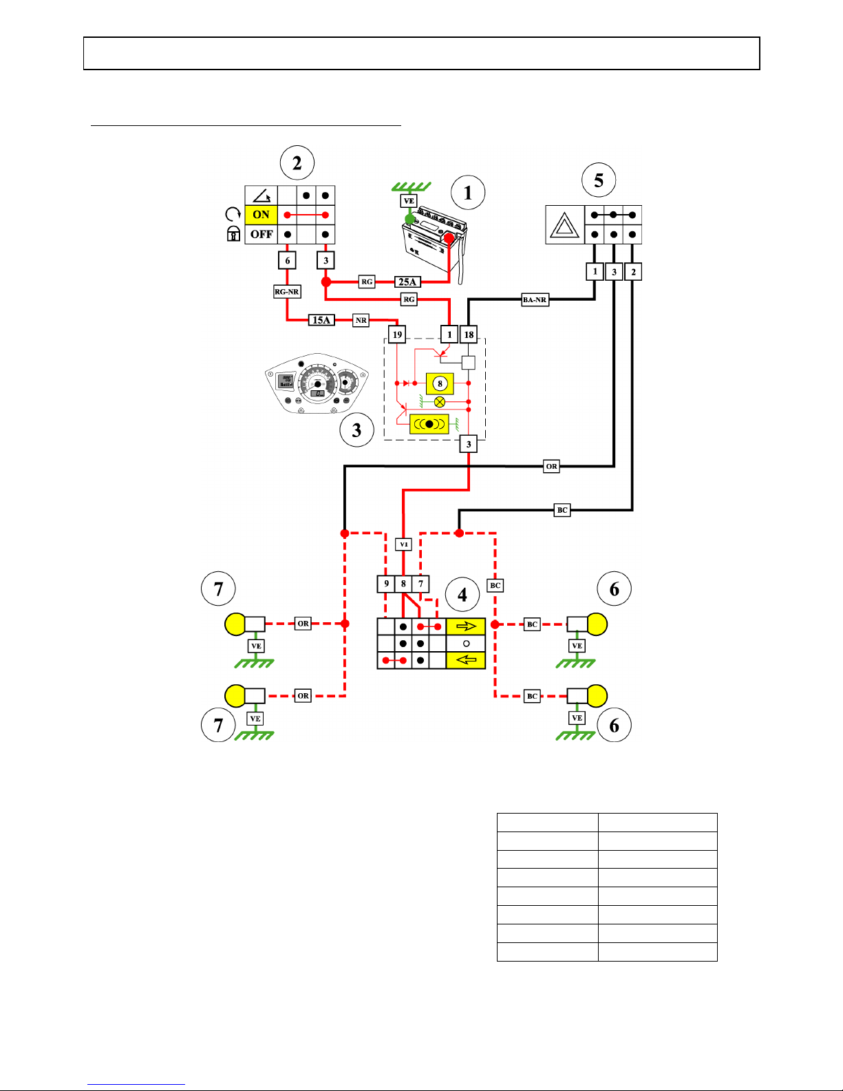
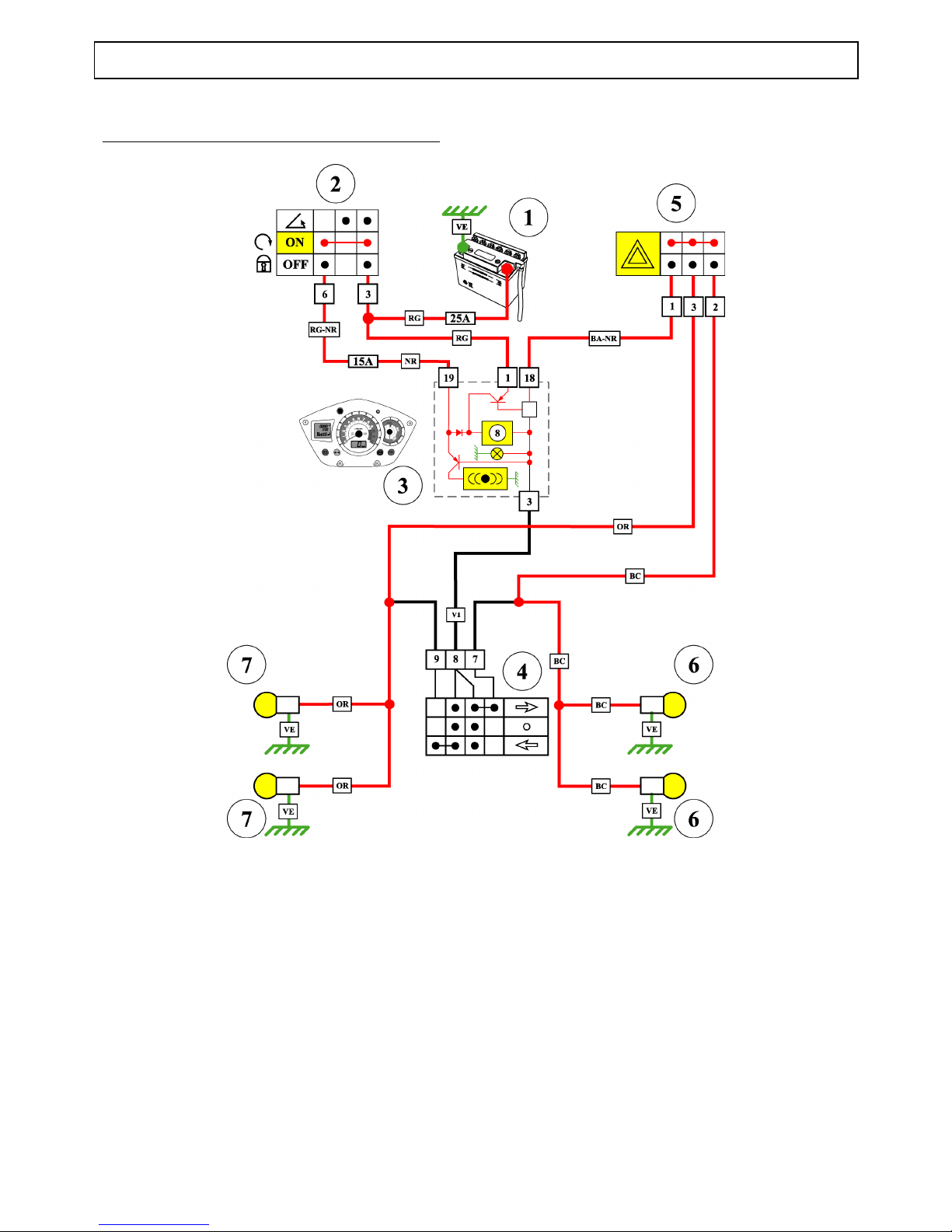
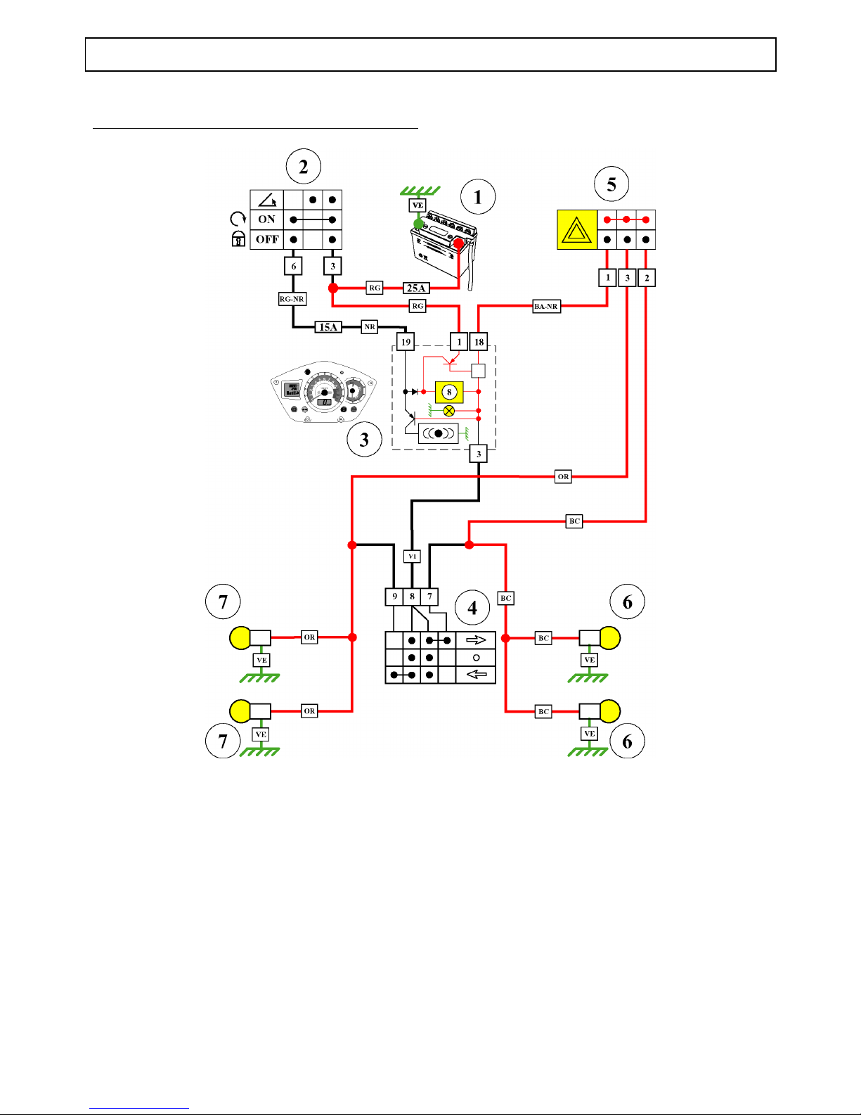
Direction indicator functioning principle (125 cc)
Direction indicator function
1. Battery
2. Ignition switch
3. Instrument cluster
4. Direction indicator switch
5. Hazard warning lights switch
6. Right direction indicator
7. Left direction indicator
8. Direction indicator unit
BA-NR White-Black
BC Light blue
JN-BE Yellow-Blue
OR Orange
RG Red
RG-NR Red-Black
VE Green
VI Mauve
Page 29
ELECTRICITY
TRAINING MANUAL: JET FORCE Page : 29/43
Reproduction or translation, even partial, is forbidden without the written consent of Peugeot Motocycles
Hazard warning lights with ignition on (125 cc)
Page 30
ELECTRICITY
TRAINING MANUAL: JET FORCE Page : 30/43
Reproduction or translation, even partial, is forbidden without the written consent of Peugeot Motocycles
Hazard warning lights without ignition on (125 cc)
Page 31
ELECTRICITY
TRAINING MANUAL: JET FORCE Page : 31/43
Reproduction or translation, even partial, is forbidden without the written consent of Peugeot Motocycles
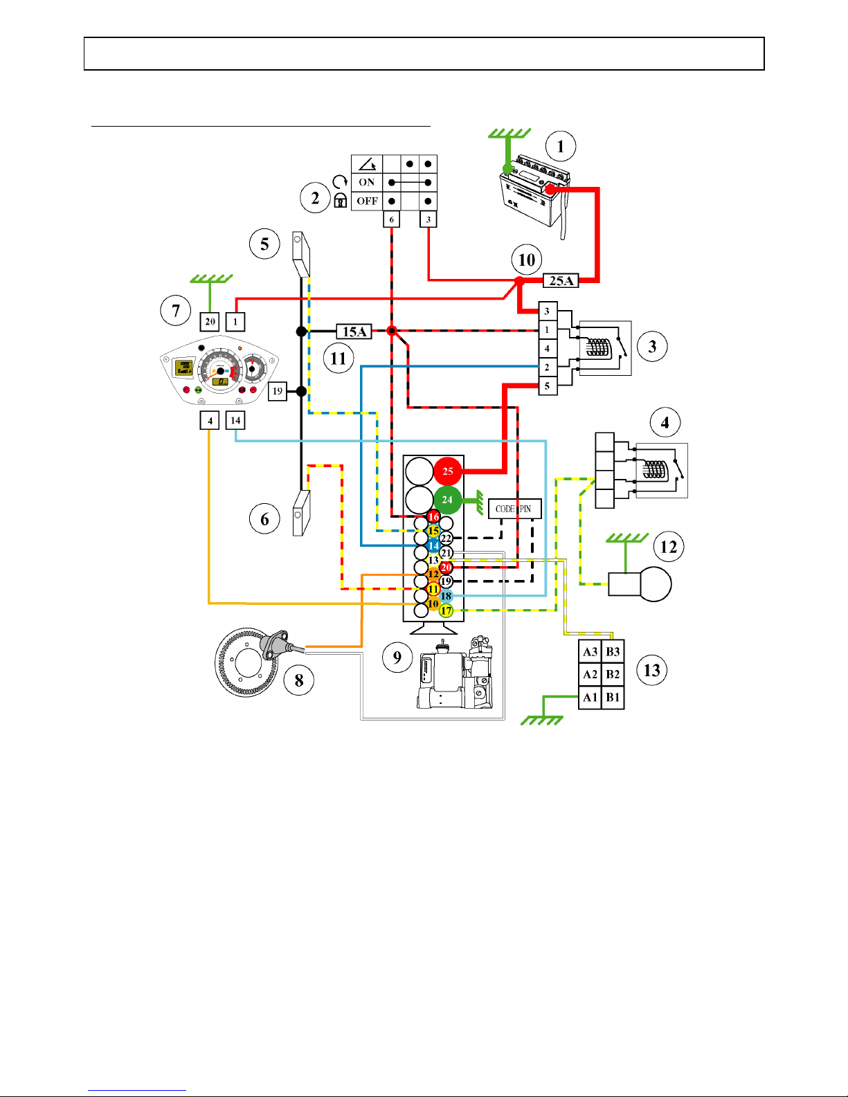
Functioning principle of the ABS/PBS system (125 cc)
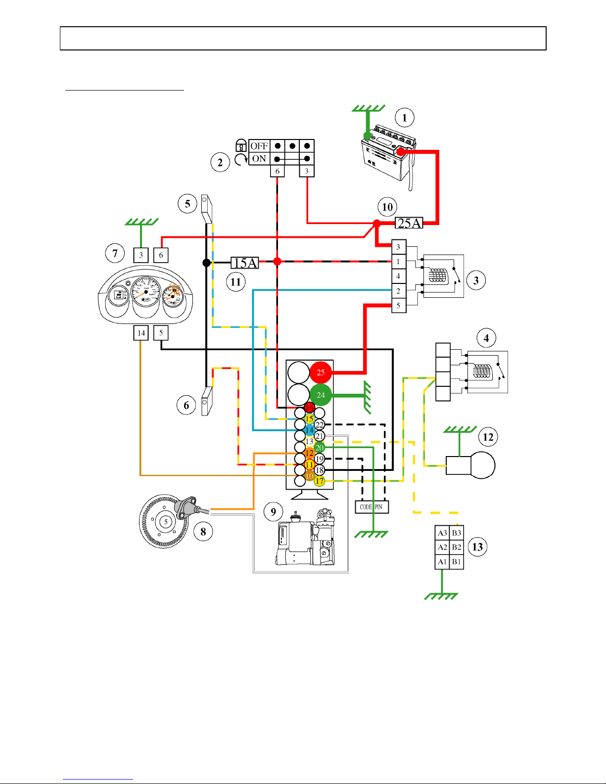
1. Battery
2. Ignition switch
3. Module main relay
4. Starter motor relay
5. RH brake contactor
6. LH brake contactor
7. Instrument cluster
8. Machine speed sensor
9. Control unit
10. 25A fuse
11. 15A fuse
12. Brake light
13. Diagnostic plug
Page 32
ELECTRICITY
TRAINING MANUAL: JET FORCE Page : 32/43
Reproduction or translation, even partial, is forbidden without the written consent of Peugeot Motocycles
ABS/PBS ELYSTAR 125cc
Page 33

TRANSPONDER IMMOBILISER
TRAINING MANUAL: JET FORCE Page : 33/43
Reproduction or translation, even partial, is forbidden without the written consent of Peugeot Motocycles
TRANSPONDER IMMOBILISER
Precautions:
Check that the diagnostic plug jumper is fitted. The jumper provides the link between the immobiliser
module and the injection/ignition ECU, and is essential to be able to start the engine
If the jumper is not fitted, the transponder LED diagnostic is always the same (no link between the
immobiliser and the ECU)
Note: Fitting of a 5 kΩ resistive suppressor along with a resistive spark plug is essential for the proper
functioning of the engine
System programming
The machine is supplied with a red key (master) and a black key
The system is programmed in the factory
It is possible to program up to 7 black keys
The key memory procedure is the same as the AEC400 and ACI100 system
Reminder of the key memory procedure
1. Using the red key, set the ignition to on, and when the LED lights, turn off the ignition
2. Within a maximum of 15 seconds of cutting off the ignition with the red key, turn on the ignition with
the black key, and when the LED comes on turn off the ignition (repeat the operation for each black
key to be memorised (maximum of 7 black keys))
3. Within a maximum of 15 seconds of turning off the ignition with the last key memorised, turn on the
ignition with the red key, and when the LED comes on, turn off the ignition
Key memory check
Using the red key, turn on the ignition, the LED on the instrument panel comes on for 0.5 seconds and
flashes a number of times. The number of flashes indicates the number of keys memorised, including the
red key
Additional information
Before carrying out any work on the transponder immobiliser, have the machine red key and black key to
hand
If the engine will not start, a first diagnostic may be carried out using the LED before checking the other
parts of the ignition system
Note: Do not remove the diagnostic plug jumper
In case of a fault, do not use an immobiliser module or ECU from another machine to carry out tests. The
keys, immobiliser module and ECU programmed on another machine form an assembly, are linked by a
code and must under no circumstances be separated
Important : If an ECU is changed without memorising the keys, do not turn on the ignition more than 16
times if the diagnostic jumper is disconnected as beyond this number, the ECU immobiliser function is
erased.
Page 34
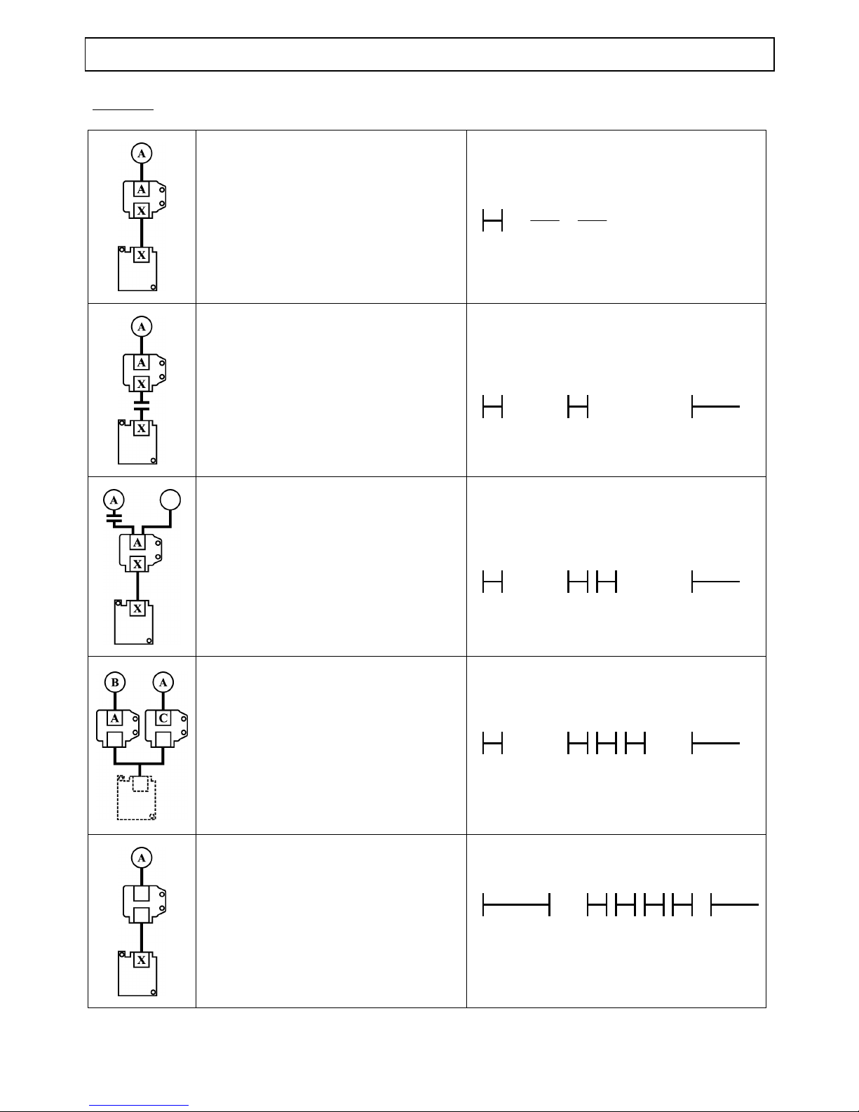
TRANSPONDER IMMOBILISER
TRAINING MANUAL: JET FORCE Page : 34/43
Reproduction or translation, even partial, is forbidden without the written consent of Peugeot Motocycles
Synoptics
Assembly correct
Cut between the immobiliser module and
the ECU
Cut between the antenna and the
immobiliser unit or no transponder in
they key
Wrong key or immobiliser module from
another machine
Blank immobiliser module
Page 35
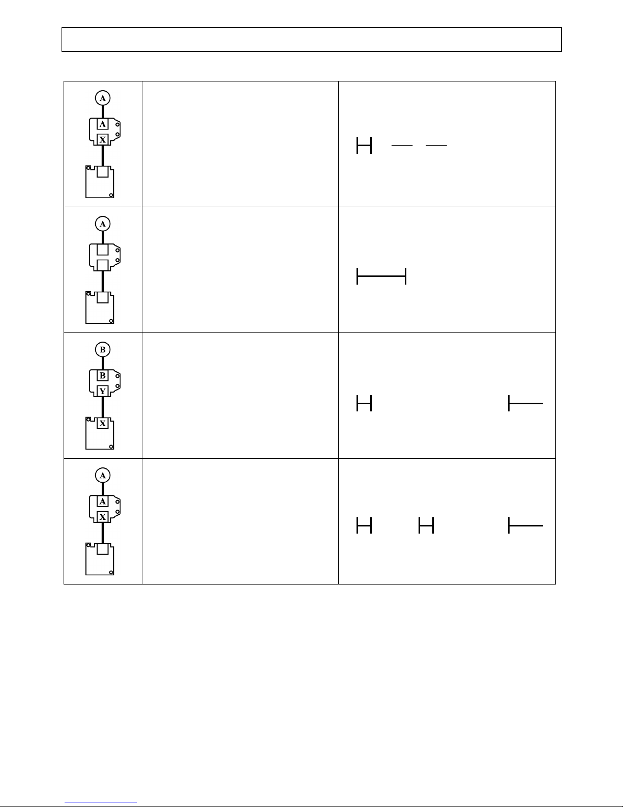
TRANSPONDER IMMOBILISER
TRAINING MANUAL: JET FORCE Page : 35/43
Reproduction or translation, even partial, is forbidden without the written consent of Peugeot Motocycles
Blank ECU
(starting possible with red key)
Immobiliser module and ECU blank
Programmed immobiliser module and
key from another machine
Blank ECU, with 16 memorised switch
on without diagnostic plug loop
Page 36
INSTRUMENT CLUSTER
TRAINING MANUAL: JET FORCE Page : 36/43
Reproduction or translation, even partial, is forbidden without the written consent of Peugeot Motocycles
INSTRUMENT CLUSTER
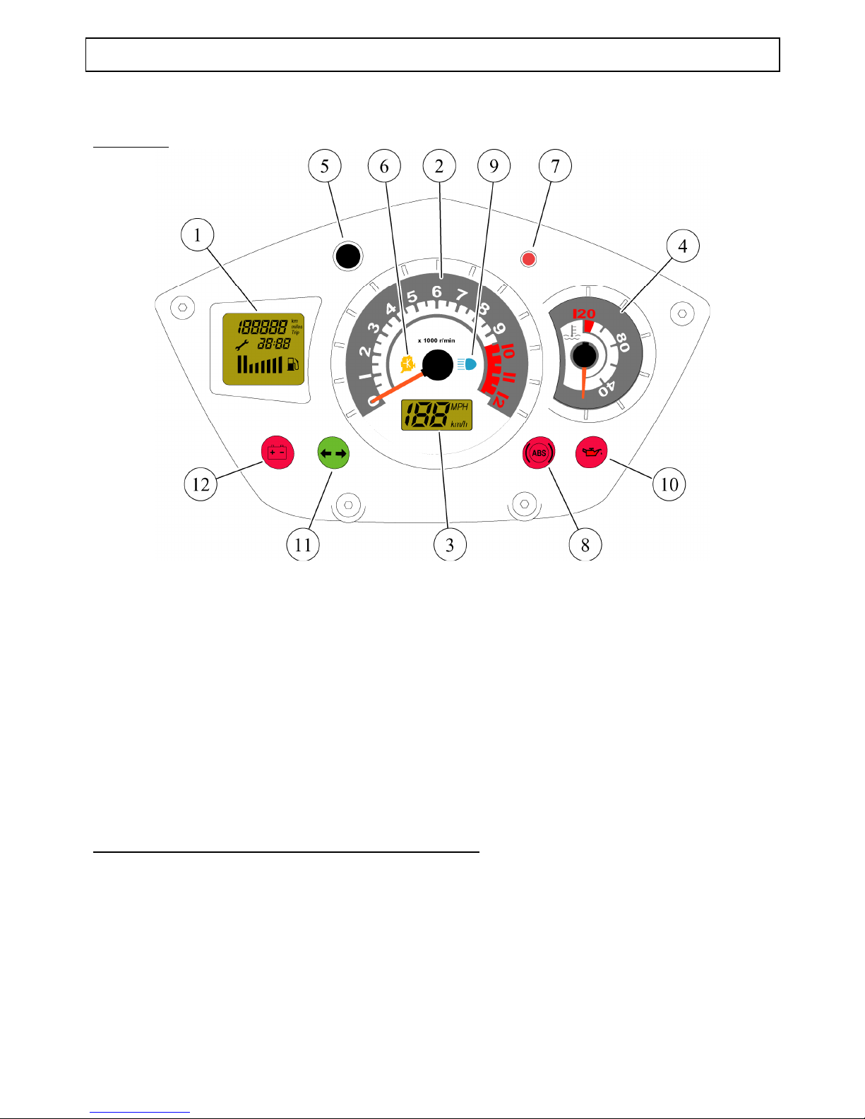
Description
1. Multi-function display
2. Rev counter
3. Speedometer
4. Engine temperature gauge
5. Control button
6. Injection system diagnostic warning light
7. Transponder immobiliser dissuasion light
8. ABS/PBS system diagnostic light
9. Headlight warning light
10. Oil low level warning light
11. Direction indicator warning light
12. Battery charge warning light
Instrument cluster self-diagnostic when ignition is turned on
Different functioning tests are carried out automatically for 5 seconds :
- Display of all of the multi-function display items (1) and the speed (3)
- Lighting of all the warning lights (except ABS/PBS depending on version)
- Test of rev counter stepper motors (2) and engine temperature (4) giving one sweep of the needles and
zero reset where necessary
Page 37
INSTRUMENT CLUSTER
TRAINING MANUAL: JET FORCE Page : 37/43
Reproduction or translation, even partial, is forbidden without the written consent of Peugeot Motocycles
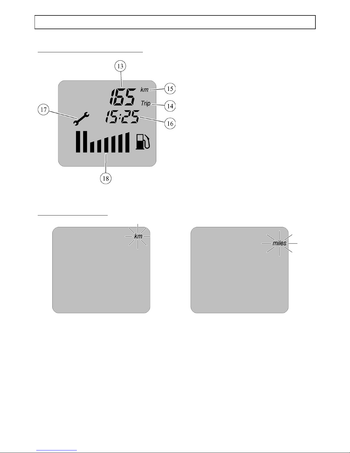
Description of the multi-function display
13. Odomètre (totaliseur ou journalier)
14. Indication de l'affichage de l'odomètre
journalier
15. Indication de l'unité utilisée par
l'odomètre
16. Horloge
17. Indicateur de maintenance (symbole
"clé")
18. Jauge à carburant
MULTI-FUNCTION DISPLAY FUNCTIONS AND SETTINGS
Changing the distance unit
- Ignition off
-Press button and hold down
-Turn on the ignition
-Release the button
-Press for <3s to select Km/Miles
-Turn off ignition to confirm
Page 38
INSTRUMENT CLUSTER
TRAINING MANUAL: JET FORCE Page : 38/43
Reproduction or translation, even partial, is forbidden without the written consent of Peugeot Motocycles
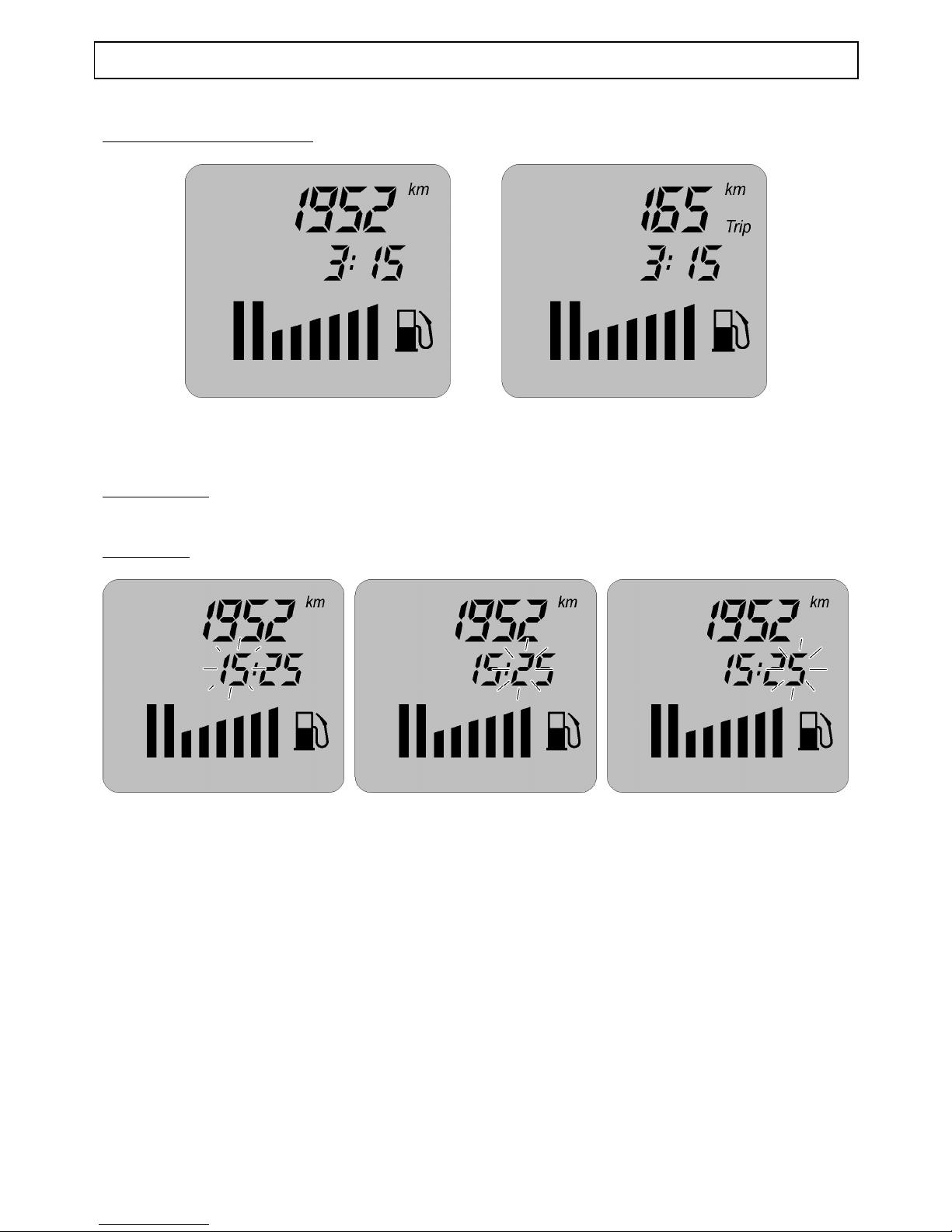
Tripmeter Total/Daily display
- Turn on the ignition
-Press and release the button to select the function required
Daily Km reset
-Hold down the button for >5s
Time setting
The time can only be set in the tripmeter total position
- Ignition on, press the button (5) until the time flashes
- Set the time by successive pushes on the control button
- Press the control button to confirm the hour, the minutes figure flashes
- Proceed in the same way to set the minutes
- Press the control button for more than 3 seconds to confirm the time
Page 39
INSTRUMENT CLUSTER
TRAINING MANUAL: JET FORCE Page : 39/43
Reproduction or translation, even partial, is forbidden without the written consent of Peugeot Motocycles
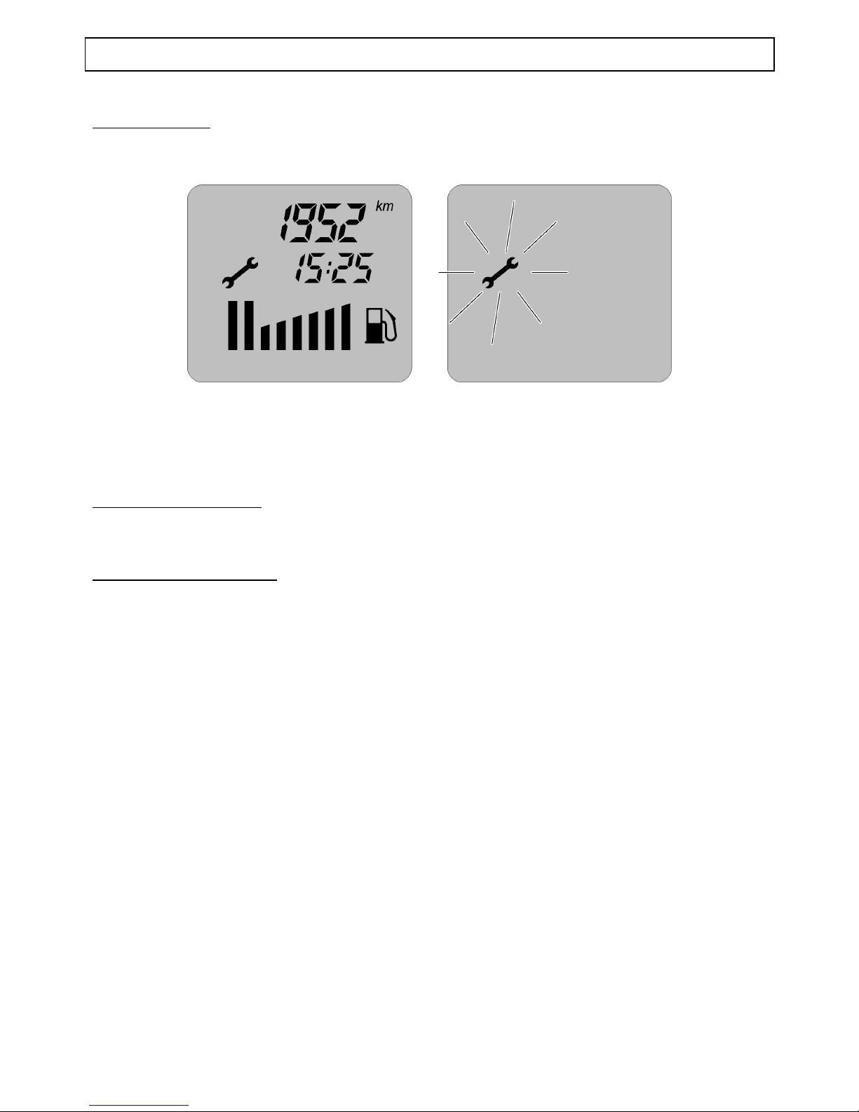
Maintenance reset
Every 5000 km a « spanner » symbol appears informing the rider that his machine is due for service
After servicing the machine, erase the symbol as follows:
- Ignition off
- Press button and hold down
-Turn on the ignition (only the spanner appears and flashes)
- Press for >5s to erase the symbol
Fuel gauge self-diagnostic
If the fuel system is cut off from the fuel gauge, when the ignition is turned on, the 8 LEDs light one after
the other
Gauge functioning (8s timer)
8 LEDs represent a full tank (10 ohms)
2 LEDs flash (75 ohms)
1 LED flashes (98 ohms)
8 LEDs flash (R> 87 ohms) means an empty tank
Page 40
LOCATION OF COMPONENTS
TRAINING MANUAL: JET FORCE Page : 40/43
Reproduction or translation, even partial, is forbidden without the written consent of Peugeot Motocycles
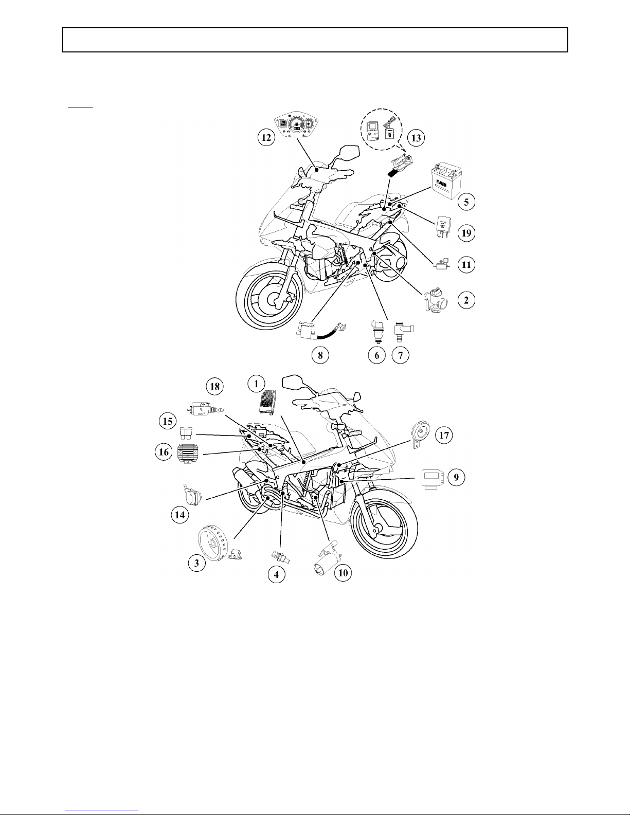
LOCATION OF COMPONENTS
50 cc
1. Injection ECU
2. Throttle unit
3. Engine position and speed sensor
4. Temperature sensor
5. Battery
6. Fuel injector
7. Air injector
8. Ignition coil
9. Immobiliser module
10. Fuel pump
11. Oil pump
12. Diagnostic light
13. Diagnostic plug
14. Air compressor
15. Fuses
16. Voltage regulator
17. Horn
18. Saddle lock
19. Starter / lighting relay
Page 41
LOCATION OF COMPONENTS
TRAINING MANUAL: JET FORCE Page : 41/43
Reproduction or translation, even partial, is forbidden without the written consent of Peugeot Motocycles
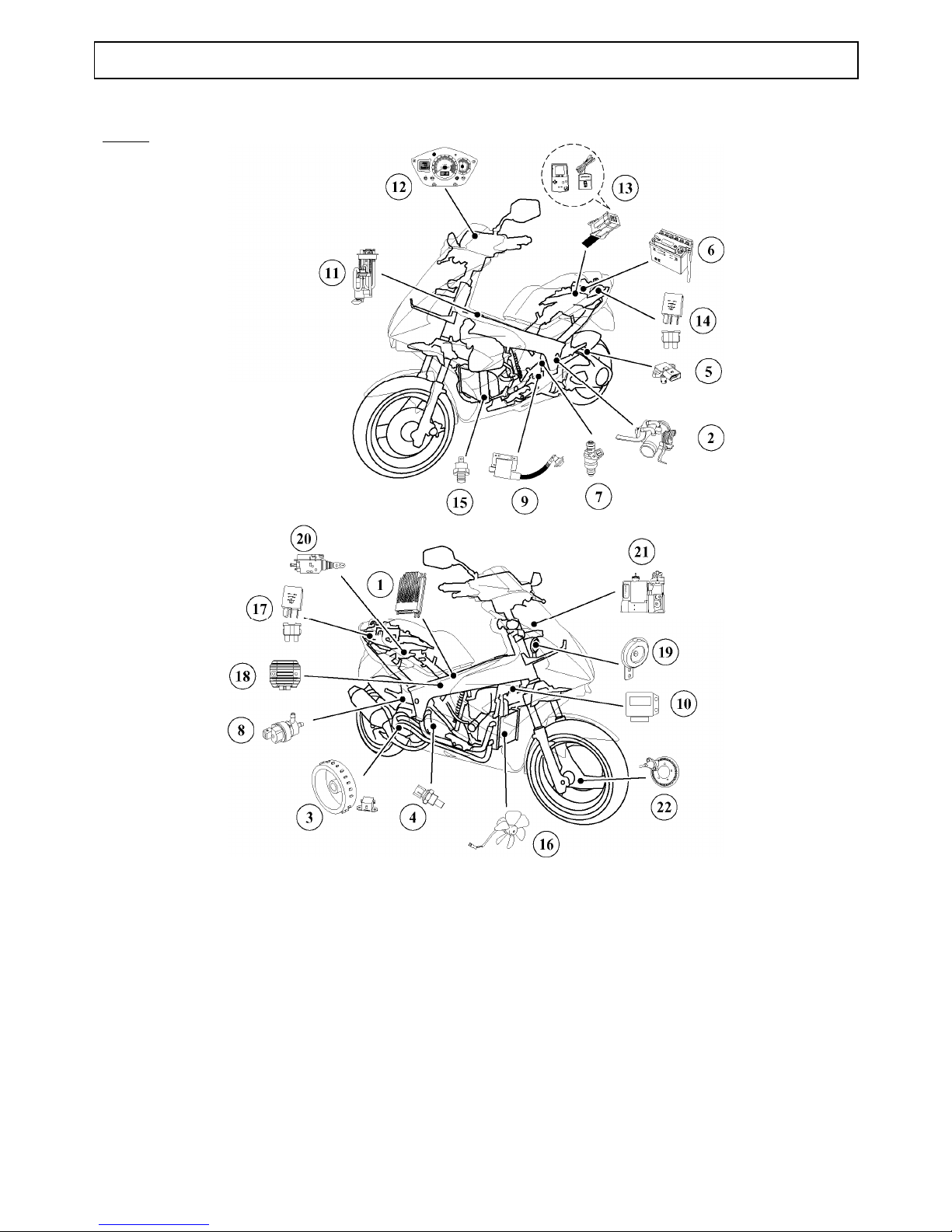
125 cc
1. Injection ECU
2. Throttle unit
3. Engine position and speed sensor
4. Temperature sensor
5. Air pressure and air temperature sensor
6. Battery
7. Fuel injector
8. Idle control valve
9. Ignition coil
10. Immobiliser module
11. Fuel pump
12. Diagnostic light
13. Diagnostic plug
14. Fuel pump relay/ABS relay/light
relay/Fuse 25A
15. Heat switch
16. Motor-driven fan
17. Fuse 15A/starter relay
18. Voltage regulator
19. Horn
20. Saddle lock
21. ABS/PBS module
22. Machine speed sensor
Page 42
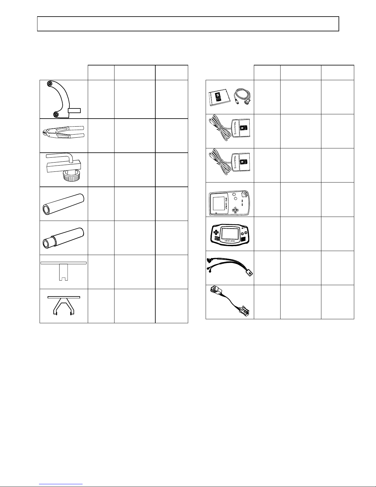
SPECIAL TOOLING
TRAINING MANUAL : Page : 42/43
SPECIAL TOOLING
. Tool N° Description Used with
756717 Engine mount
adapter
125 cc
750539 Tie-wrap pliers
755996 Pipe clamp
755986 air injector
setting tool
50 cc
755989 air injector drift
50 cc
replaces
756076
Tank gauge
spanner
756716
replaces
755056
Tank ring
spanner
. Tool N° Description Used with
755990 Diagnostic tool
update software
Computer
755878
755806
755807
755806 Cartridge
Europe
755878
755807 Cartridge Export 755878
755878 Diagnostic tool
(game boy
color)
755806
756714
replaces
755878
Diagnostic tool
(game boy
advance)
755806
755807
756017 50 cc fuel
injector power
supply harness
756449 ABS/PBS
interface cable
for diagnostic
tool
125 cc
Page 43
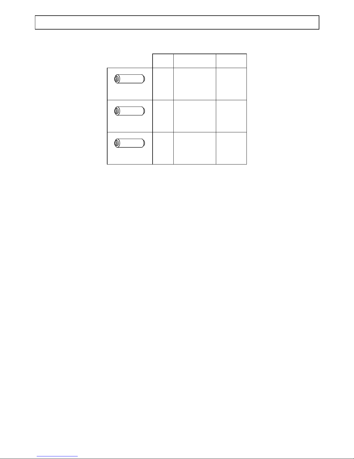
SPECIAL TOOLING
TRAINING MANUAL : Page : 43/43
. Tool N° Description
Used with
756607 Fork seal fitting
tool
125 cc
756608 Fork seal fitting
tool
50 cc
756668 Crank assembly
lip seal tool
50 cc
 Loading...