

Page 1
Sales division
Technical network leadership
WORKSHOP MANUAL
-
Page 2

Sales division
Technical network leadership
Reproduction or translat ion, even partial, is forbi dden without the written co nsent of Peugeot Motocyc les
Page 3

TABLE OF CONTENTS
1
Reproduction or translation, even partial, is forbidden without the written consent of Peugeot Motocycles
TABLE OF CONTENTS
TABLE OF CONTENTS . ... ....................................... ... ... ... .... ... ....................................... ... ... ... ... ....................... 1
CHARACTERISTICS......................................................................................................................................... 3
Engine........................................................................................................................................................3
Capacities. .................................................................................................................................................3
Chassis......................................................................................................................................................4
Dimensions and weight................................................. ... ... ... .... ... ....................................... ......................4
Tyres. .........................................................................................................................................................4
Chassis markings.......................................................................................................................................4
Engine marking..........................................................................................................................................4
SERVICE SCHEDULE AND COMMISSIONING............................................................................................... 5
Check.........................................................................................................................................................5
Change. .....................................................................................................................................................5
Check and lubricate. ..................................................................................................................................6
Clean and adjust.............................................................. ....................................... ... ... ... . .........................6
Test machine..............................................................................................................................................6
Battery preparation (Except battery without maintenance)*. .....................................................................7
Checks before handing over to the customer.............................................................................................7
SPECIAL IMPORTANT POINTS....................................................................................................................... 8
Oil and fuel.................................................................................................................................................8
Starting up after overhauling the engine....................................................................................................8
TIGHTENING TORQUES ................................. .... ... ... ... ... .......................................... .... ... ................................ 9
Body panels. ..............................................................................................................................................9
Cycle part...................................................................................................................................................9
Standard. ...................................................................................................................................................9
SPECIAL TOOLS ............................................................................................................................................ 10
LOCATION OF COMPONENTS...................................................................................................................... 11
BODY PANELS ............................................................................................................................................... 12
Removal of the front shield panel.............................................................................................................12
Removal of front lower shield panels. ......................................................................................................12
Removing the footboard and the LH tunnel. ....... ............................................................................. ........12
Removal of the storage compartment......................................................................................................13
Removal of the rear cover assembly and mudflap...................................................................................14
Removal of the header tank.....................................................................................................................14
ELECTRIC COMPONENTS ............................................................................................................................ 15
Removal of the blinker unit.......................................................................................................................15
Page 4

TABLE OF CONTENTS
2
Reproduction or translation, even partial, is forbidden without the written consent of Peugeot Motocycles
Removal of the ignition module................................................................................................................15
Removal of the headlight bulbs................................................................................................................15
Removal of the horn.................................................................................................................................16
Removal of the oil pump control unit........................................................................................................16
Removal of the regulator..........................................................................................................................16
Removal of the engine temperature sensor.............................................................................................16
Removal of the oil pump. .........................................................................................................................16
Removal of the high tension coil..............................................................................................................17
PETROL CIRCUITS.........................................................................................................................................18
Removal of the fuel tank filter...................................................................................................................18
Removal of the fuel pump........................................................................................................................18
Removal of the carburettor.......................................................................................................................19
Procedure to position the carburettor.......................................................................................................20
Removal of the inlet coupling and valves.................................................................................................21
Removal of the inlet coupling and valves.................................................................................................21
Removal of the throttle valve....................................................................................................................21
WORKING ON THE ENGINE WITHOUT REMOVING THE ENGINE.............................................................22
Removal of the air pump..........................................................................................................................22
Removal of the cylinder / piston...............................................................................................................22
Removal of the water pump.....................................................................................................................23
MISCELLANEOUS OPERATIONS ................................................................................................................. 24
Removal of the rear brake pad.................................................................................................................24
Page 5
CHARACTERISTICS
3
Reproduction or translation, even partial, is forbidden without the written consent of Peugeot Motocycles
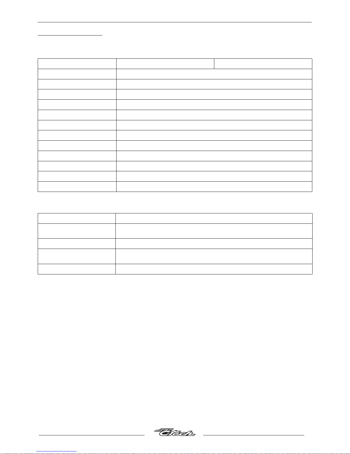
CHARACTERISTICS
Engine.
Capacities.
Jet C-Tech 307 WRC
Type. 2-stroke single-cylinder.
Cooling. Liquid.
Bore x stroke. 39.9 x 39.8 mm.
Cubic capacity. 49.9 cc.
Max. power output. 3.6 kW at 7300 rpm.
Max. torque rating. 7000 rpm.
Fuel supply. Carburettor Gurtner PY15.
Lubrication. Electric oil pump.
Transmission. By 2 variable pulleys and V-type belt.
Clutch. Centrifugal automatic.
Spark plug. NGK CR7EB.
Exhaust. Catalytic.
Fuel tank. 7.8 l 95 or 98 lead-free.
Oil tank.
1.2 l.
Semi synthetic for 2 stroke engines with separate oiling.
Relay box. 0.12 l SAE 80W90 life lubricated.
Coolant.
1.4 l.
Peugeot coolant part number 754614.
Fork. 0.12 l per tube (Esso Univis 46 or Agip H Lift 46).
Page 6
CHARACTERISTICS
4
Reproduction or translation, even partial, is forbidden without the written consent of Peugeot Motocycles
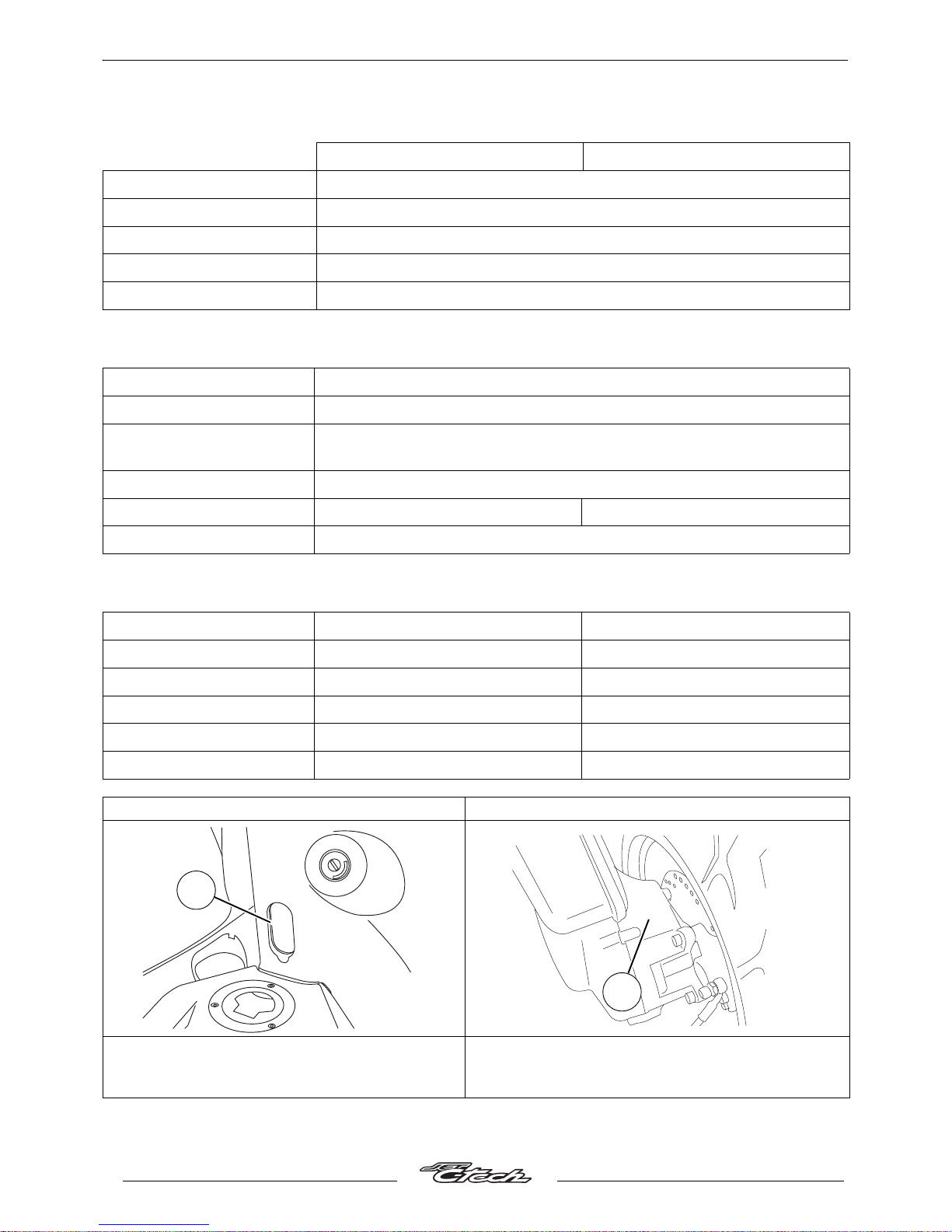
Chassis.
Dimensions and weight.
Tyres.
Jet C-Tech 307 WRC
Chassis. Steel wrap-round frame (Direct Perimetric Frame)
Front suspension. Ø32 mm telescopic fork.
Travel. 85 mm.
Rear suspension. Central shock absorber.
Travel. 95 mm.
Overall length.
1915 mm.
Width at handlebar.
720 mm.
Height (without rear-view
mirrors)
1165 mm.
Wheelbase.
1340 mm.
Saddle height.
820 mm. 810 mm.
Unladen weight.
114 kg.
Front wheel rim. 12 inch aluminium alloy. 13 inch aluminium alloy.
Front tyre. 120/70 - 12. 130/60 - 13.
Front tyre pressure. 1.6 bars. 2.2 bars.
Rear wheel rim. 12 inch aluminium alloy. 13 inch aluminium alloy.
Rear tyre. 130/70 - 12. 130/60 - 13.
Rear tyre pressure. 1.8 bars. 2.2 bars.
Chassis markings. Engine marking.
1. VIN number.
- Manufacturer's plate located under the
saddle.
2. Engine number.
*
xxxxxxxxxx
*
1
XXXXXXXXXX
XXX
2
Page 7
SERVICE SCHEDULE AND COMMISSIONING
5
Reproduction or translation, even partial, is forbidden without the written consent of Peugeot Motocycles
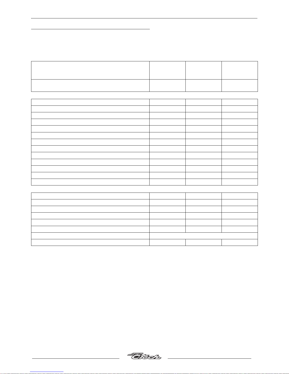
SERVICE SCHEDULE AND COMMISSIONING
Heavy duty servicing is for vehicles used under "harsh" conditions: door-to-door deliveries, intensive
urban use (courier), short journeys with engine cold, dusty areas, ambient temperature over 30°C.
* Depending on equipment.
# Change if necessary.
Service operations.
500 kms or
1 months.
Every
5000 kms or
12 months.
Every
10000 kms.
Heavy duty servicing. 500 kms.
Every
2500 kms.
Every
5000 kms.
Check.
Idle setting. X X X
Throttle cable play. X X X
Steering column play. X X X
Operation of electrical equipment. X X X
Condition of front and rear brak e hydraulic controls *. X X X
Condition of petrol pipes. X X X
Condition of oil pipes. X X X
Tyre pressures. X
Tyre condition, pressure and wear. X X
Brake fluid level. X X X
Battery electrolyte level. X X X
Coolant level. X X X
Tightness of nuts and bolts. X X X
Change.
Spark plug. X X
Intake silencer. X
Front brake pads #. X X
Rear brake pads #. X X
Drive pulley bearings and guides #. X X
Transmission belt. X
Brake fluid and coolant. Once every 2 years
Petrol filter. X
Page 8
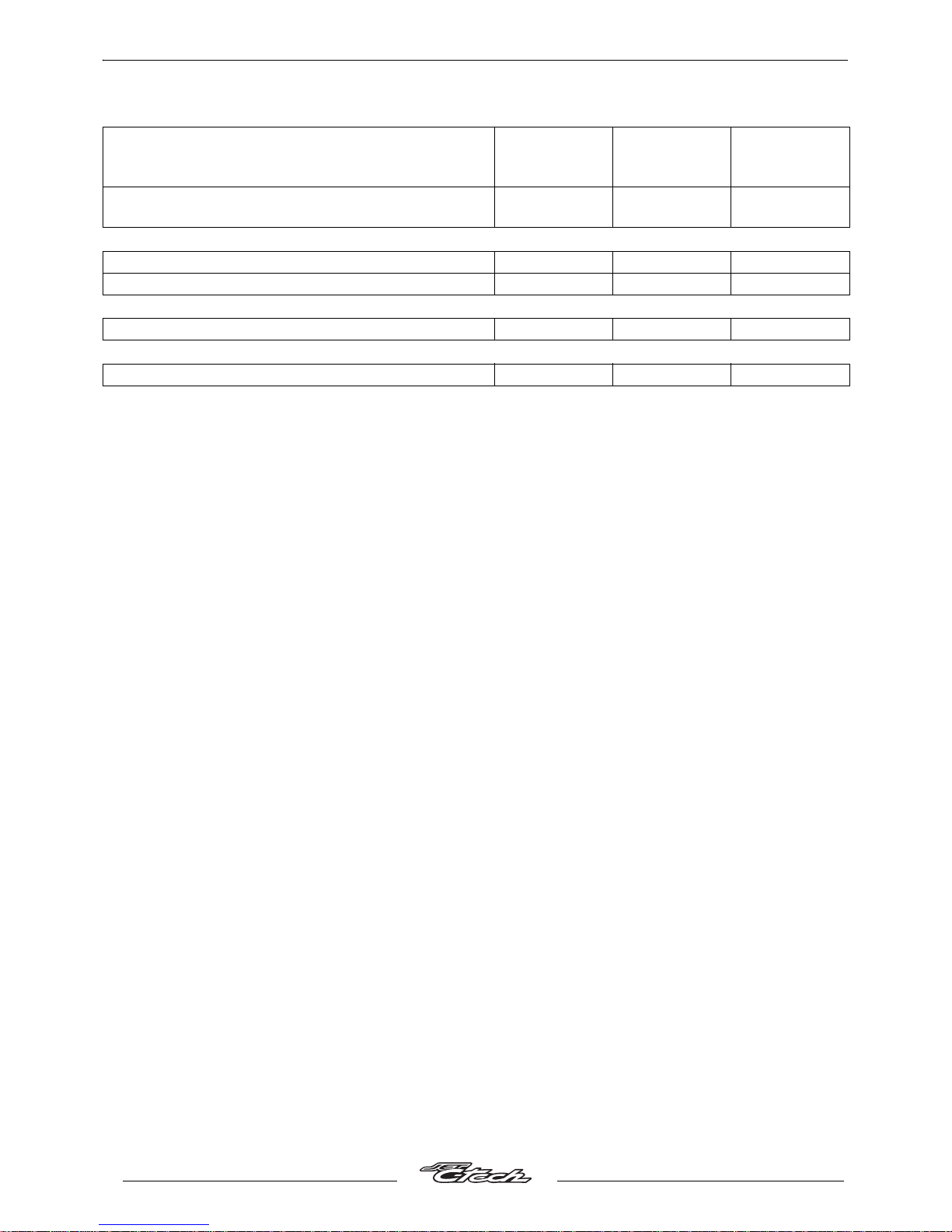
SERVICE SCHEDULE AND COMMISSIONING
6
Reproduction or translation, even partial, is forbidden without the written consent of Peugeot Motocycles
* Depending on equipment.
# Change if necessary.
Service operations.
500 kms or
1months.
Every
5000 kms or
12 months.
Every
10000 kms.
Heavy duty servicing. 500 kms.
Every
2500 kms.
Every
5000 kms.
Check and lubricate.
Driven pulley: Moving flange and needle bush. X
Kick lever boss/Kick starter control shaft. X X
Clean and adjust
Carburettor X
Test machine.
On road. X X X
Page 9

SERVICE SCHEDULE AND COMMISSIONING
7
Reproduction or translation, even partial, is forbidden without the written consent of Peugeot Motocycles
Battery preparation (Except battery without maintenance)*.
Remove the battery.
Remove the 6 filler caps and the vent plug.
Fill with electrolyte to the level marked "UPPER LEVEL".
Electrolyte: (35% sulfuric acid = 1.28 g/cm
3
)
1 litre can P/N 752740.
5 litre can P/N 752741.
Leave the battery to stand for around half an hour.
Top up if necessary.
Charge the battery for at least 2 hours with a current of 0.4A.
Refit the battery and connect the vapour vent pipe.
Connect the red wire lug to the battery's + terminal, and the green wire lug to the battery's - terminal.
Then, the battery level should be topped up if necessary, after fully charging, using distilled water only.
Checks before handing over to the customer.
Check the wheel nuts are tight.
Check nuts and bolts are tight.
Check brake adjustment and efficiency.
Check the tyre pressures cold.
Check operation of the lights, flashers, horn, and brake light.
Check the different warning lights work.
Carry out a road test with the machine.
* Depending on equipment.
Page 10
SPECIAL IMPORTANT POINTS.
8
Reproduction or translation, even partial, is forbidden without the written consent of Peugeot Motocycles
SPECIAL IMPORTANT POINTS.
Oil and fuel.
This engine is designed to run on 95 or 98 unleaded fuel only.
The oil to use for the separate lubrication system is "Esso 2T Special" or "Esso 2T Special low-
smoke" oil approved by the manufacturer.
The fuel pipes must be changed if they show signs of wear, cracks, etc.
The air pipe between the air pump and the exhaust is specific owing to its heat resistance
properties.
Should it be changed, replace it with a genuine pipe.
Petrol is highly inflammable, do not smoke in the working area and avoid pr oximity to flames or
sparks. Work in a clear and well-ventilated area.
Before carrying out any work, leave the engine to cool for at least 2 hours.
Starting up after overhauling the engine.
The oil pump must be drained in accordance with the recommended procedures.
When switching on the ignition, the "STOP" warning light on the instrument cluster goes on and then
goes off when the engine is alive. This indicates that the warning light and the electric system of the
lubricating system are operational.
When starting the engine hot or cold do not accelerate.
Check the coolant level in the header tank.
Page 11
TIGHTENING TORQUES
9
Reproduction or translation, even partial, is forbidden without the written consent of Peugeot Motocycles
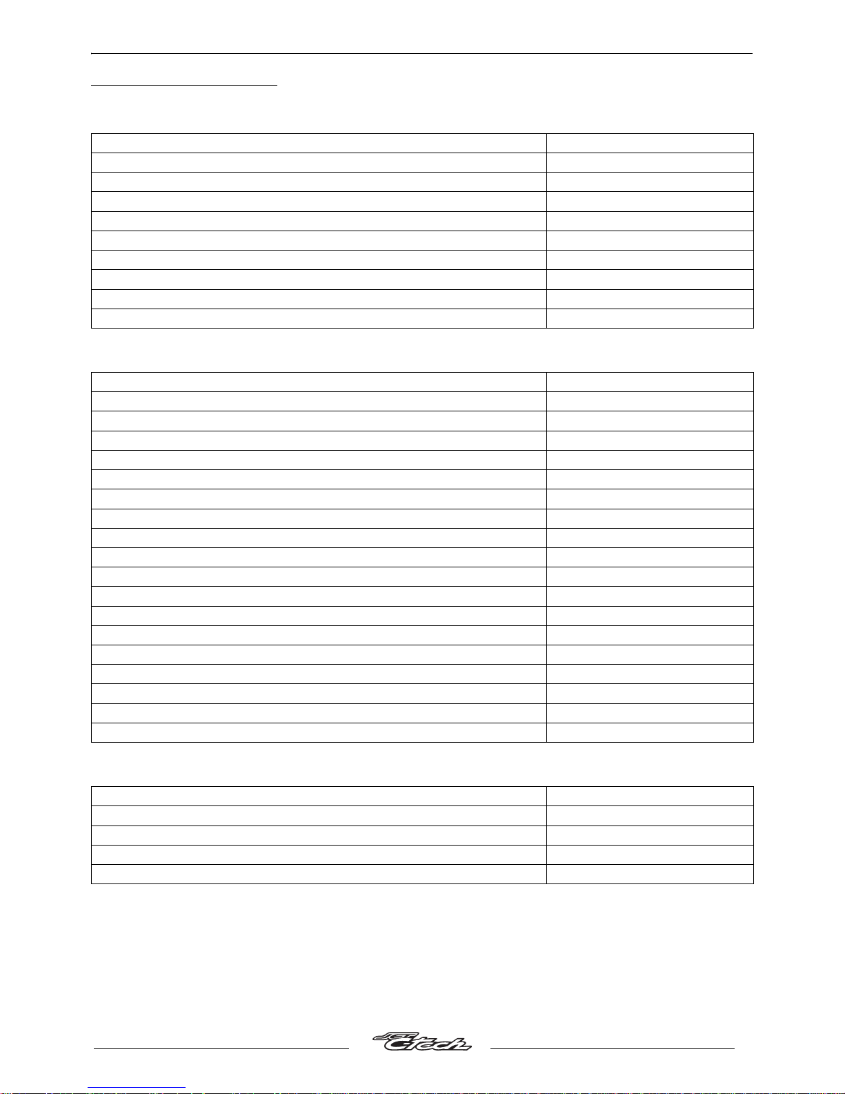
TIGHTENING TORQUES
Body panels.
Cycle part.
Standard.
Front mudguard. 1 m.daN.
Handlebar cover. 0.1 m.daN.
Front shield panels. 0.1 m.daN.
Rear shield. 0.1 m.daN.
Bottom panel. 0.1 m.daN.
Footboard. 1 m.daN.
Saddle storage compartment. 1 m.daN.
Rear cover. 0.4 m.daN.
Grab handle. 2.2 m.daN.
Rear mudguard. 1 m.daN.
Front wheel spindle. 6.5 m.daN.
Rear wheel bolt. 9 m.daN.
Rear wheel spindle nut. 11 m.daN.
Linkrod to engine pivot. 4.5 m.daN.
Linkrod to swingarm. 4.5 m.daN.
Engine-upper linkrod pivot. 4.5 m.daN.
Shock absorber top mount. 2.5 m.daN.
Shock absorber bottom mount. 2.5 m.daN.
Front and rear frame mounting nut. 2.2 m.daN.
Exhaust to cylinder mounting nut. 1.5 m.daN.
Exhaust to casing mounting bolt. 2.2 m.daN.
Upper cone (in 2 operations). 3.8/2.3 m.daN.
Upper cone locknut. Hand tightened.
Steering locknut. 7.5 m.daN.
Front brake caliper. 3 m.daN.
Rear brake caliper. 2.2 m.daN.
Front brake disc. 1 m.daN.
Rear brake disc. 1 m.daN.
Handle bar. 3 m.daN.
Nut and bolt 5 mm diameter. 0.5 m.daN.
Nut and bolt 6 mm diameter. 1 m.daN.
Nut and bolt 8 mm diameter. 2.2 m.daN.
Nut and bolt 10 mm diameter. 3.5 m.daN.
Nut and bolt 12 mm diameter. 5.5 m.daN.
Page 12
SPECIAL TOOLS
10
Reproduction or translation, even partial, is forbidden without the written consent of Peugeot Motocycles
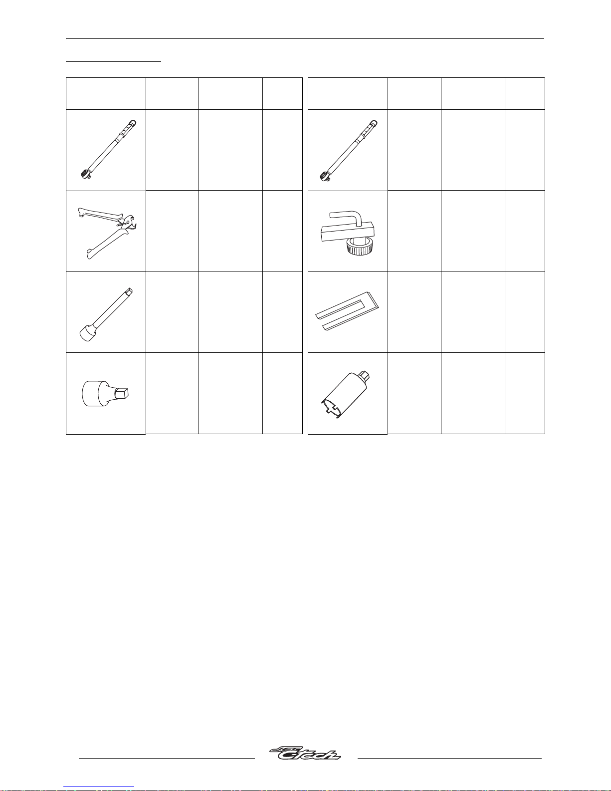
SPECIAL TOOLS
Tool N°. Designation.
Used
with.
Tool N°. Designation.
Used
with.
068994
Torque
wrench
8 N.m to
54 N.m.
752235
752236
753977
Torque
wrench
30 N.m to
150 N.m.
752235
752236
750539
Tie-wrap
pliers.
755996 Hose clamp.
752235
1/2 extension
.
68994
or
753977
756575
Piston
locking fork
752236
1/23/8 adapter.
68994
or
753977
757860 Steering tool
Page 13
LOCATION OF COMPONENTS
11
Reproduction or translation, even partial, is forbidden without the written consent of Peugeot Motocycles
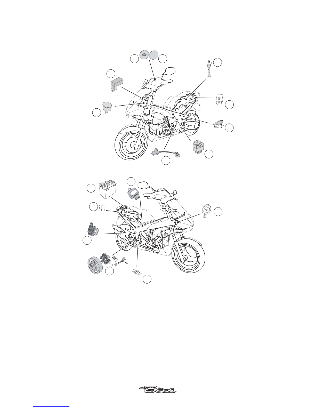
LOCATION OF COMPONENTS
1. Oil pump control unit.
2. Battery.
3. Ignition sensor.
4. CDI unit.
5. Oil level indicator.
6. Oil pump.
7. HT coil.
8. Low oil level warning light.
9. STOP light.
10. Regulator.
11. Starter motor relay.
12. Flasher unit.
13. Horn.
14. Engine temperature sensor.
15. 7.5 A fuse.
16. Air pump.
7
10
6
11
2
5
4
12
3
1
15
16
8 9
13
14
1
2
V
2
5
A
-
U
P
P
E
R
L
E
V
E
L
L
O
W
E
R
L
E
V
E
L
STOP
NC
NC
Page 14
BODY PANELS
12
Reproduction or translation, even partial, is forbidden without the written consent of Peugeot Motocycles
BODY PANELS
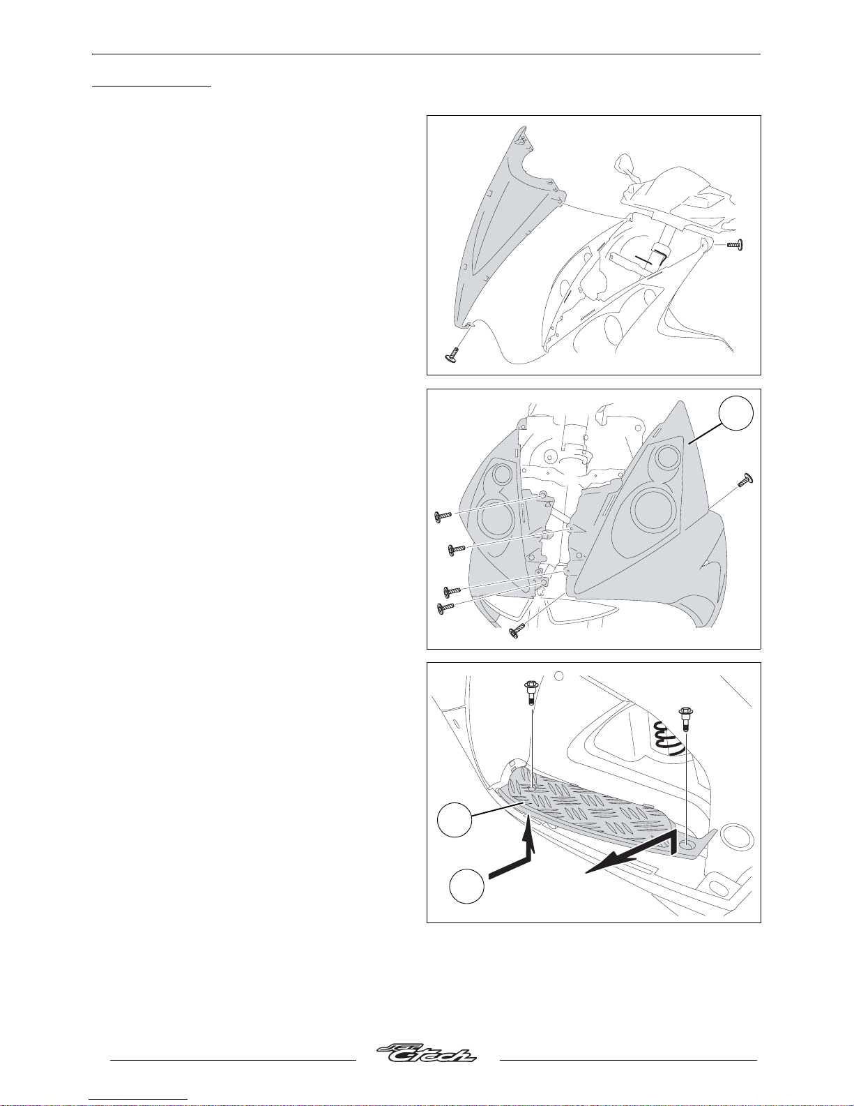
Removal of the front shield panel.
Procedure 1.
- Remove the front upper shield panel
(3 screw).
Removal of front lower shield panels.
Procedure 2.
- Remove the front lower left shield panel (1)
(3 screws), including the 2 fixing it to the RH
shield panel
- Remove the front lower RH shield panel
(3 screw).
Removing the footboard and the LH
tunnel.
Procedure 3.
- Remove the 2 screws that hold the LH
footboard (1).
- Unclip the outer part of the footboard starting
at the rear.
- Unclip the footboard from the frame bottom.
- Raise the footboard by levering on the front
end (A) to release it from the rear shield panel.
1
1
1
A
Page 15
BODY PANELS
13
Reproduction or translation, even partial, is forbidden without the written consent of Peugeot Motocycles
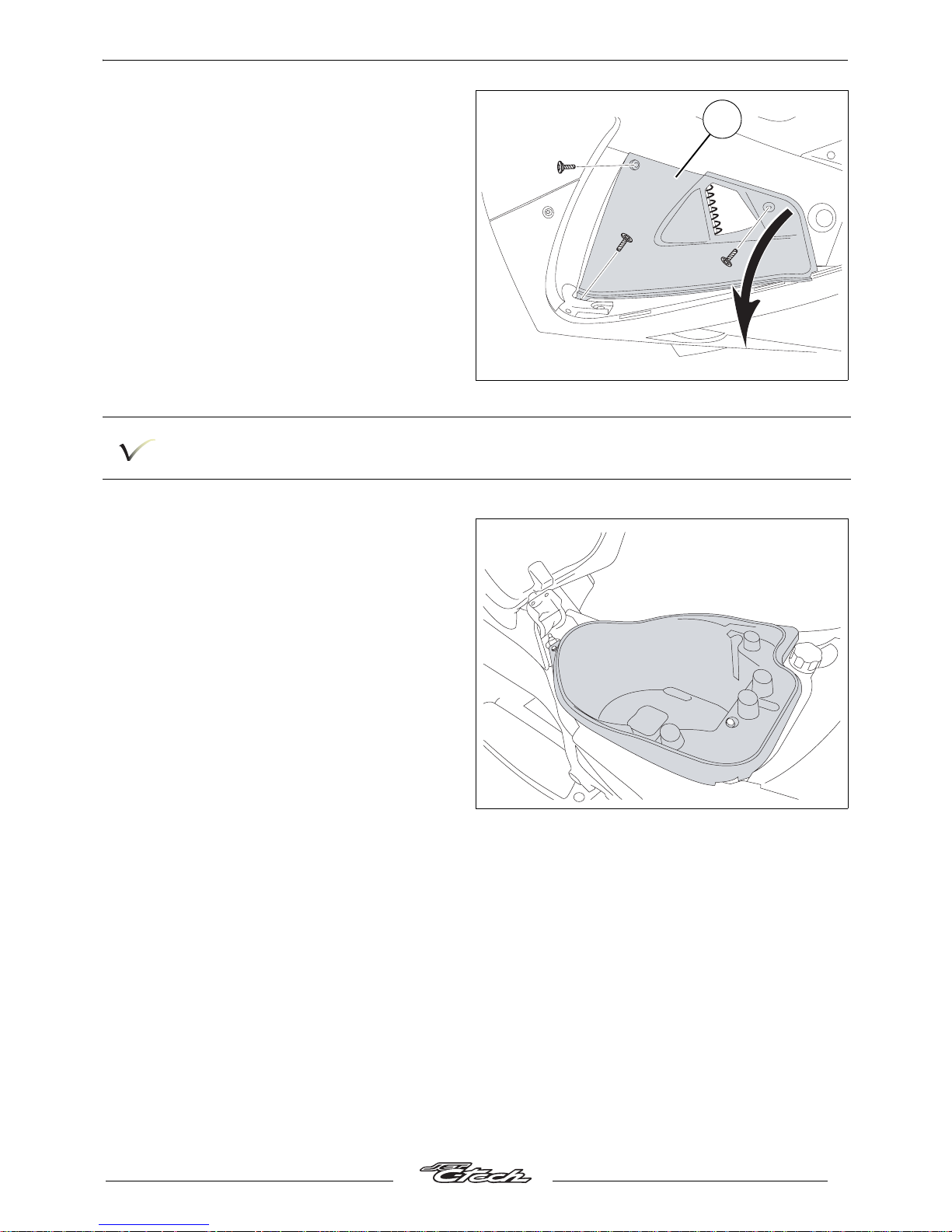
- Remove the LH tunnel (2) by releasing it from
the rear upper part.
Carry out the same operation for the RH side.
Removal of the storage compartment.
Procedure 4.
- Lift the saddle.
- Remove the storage compartment (6 nuts).
2
Page 16
BODY PANELS
14
Reproduction or translation, even partial, is forbidden without the written consent of Peugeot Motocycles
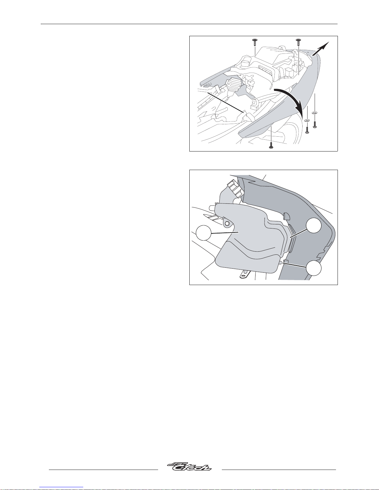
Removal of the rear cover assembly and
mudflap.
- Remove the storage compartment (see
procedure 4).
- Remove the passenger seat (2 screw).
- Remove the rear handle (3 nuts).
- Disconnect from the locking plate the cable
that controls the opening of the seat.
- Remove the rear cover 8 fixing screws.
- Disconnect the tail light and the turnsignal
lights.
- Remove the rear cover assembly (unclip the
rear cover from the storage compartment trim,
fed one side of the panel under the battery
bracket, pull the cover clear by turning it on the
same side).
Removal of the header tank.
- Remove the front upper shield panel (see
procedure 1).
- Removal of front lower shield panels (see
procedure 2).
- Empty the header tank.
- Disconnect the header tank pipes.
- Remove the upper fixing bolts.
- Clear the header tank (1) from the bracket
guides and rear shield.
- Remove the header tank.
1
A
B
Page 17
ELECTRIC COMPONENTS
15
Reproduction or translation, even partial, is forbidden without the written consent of Peugeot Motocycles
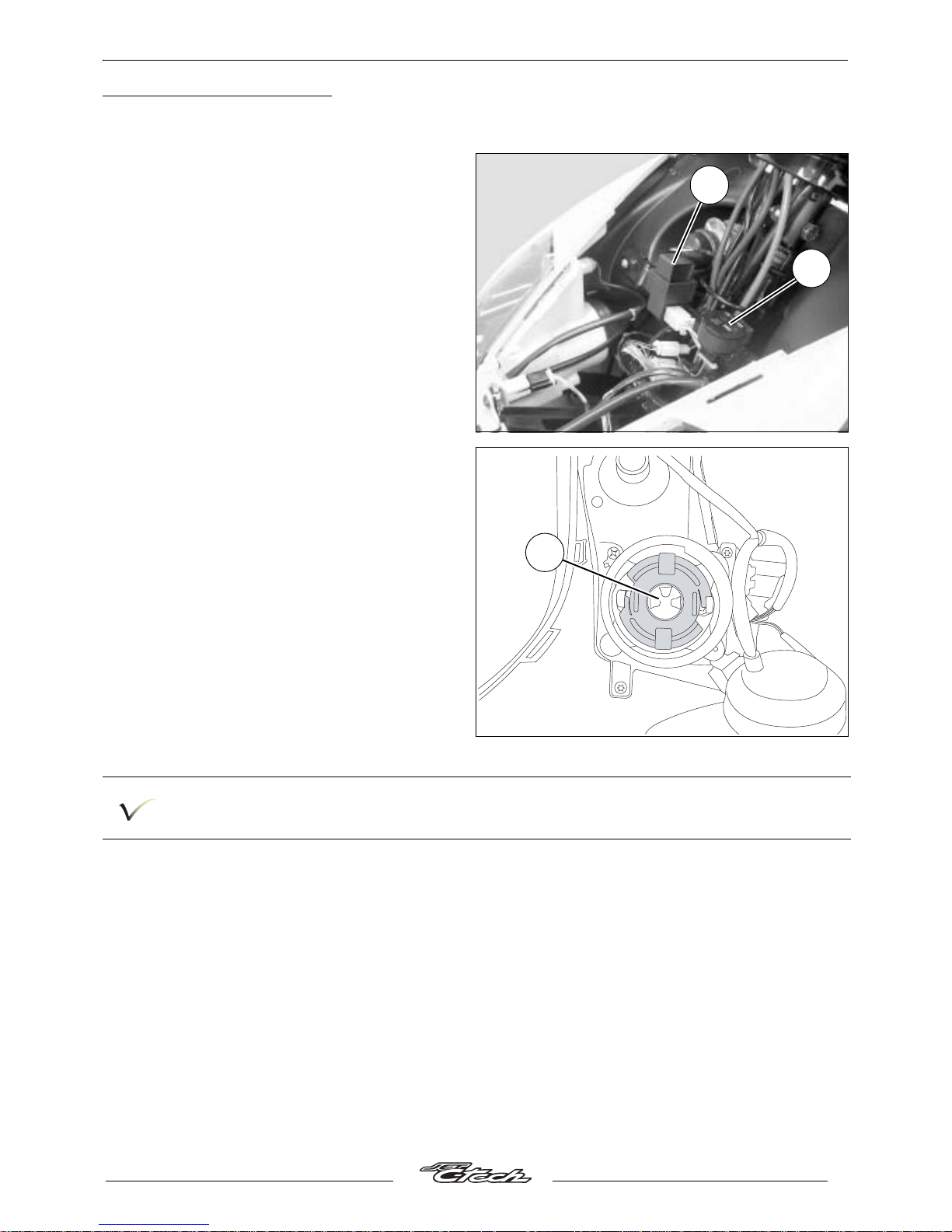
ELECTRIC COMPONENTS
Removal of the blinker unit.
Removal of the ignition module.
- Remove the front upper shield panel (see
procedure 1)
- Disconnect and remove the blinker unit (1).
- Disconnect and remove the ignition
module (2).
Removal of the headlight bulbs.
- Remove the bulbs (3).
The bulbs are held in the headlight by means of a plate which is locked by turning i t to the right.
2
1
3
Page 18
ELECTRIC COMPONENTS
16
Reproduction or translation, even partial, is forbidden without the written consent of Peugeot Motocycles
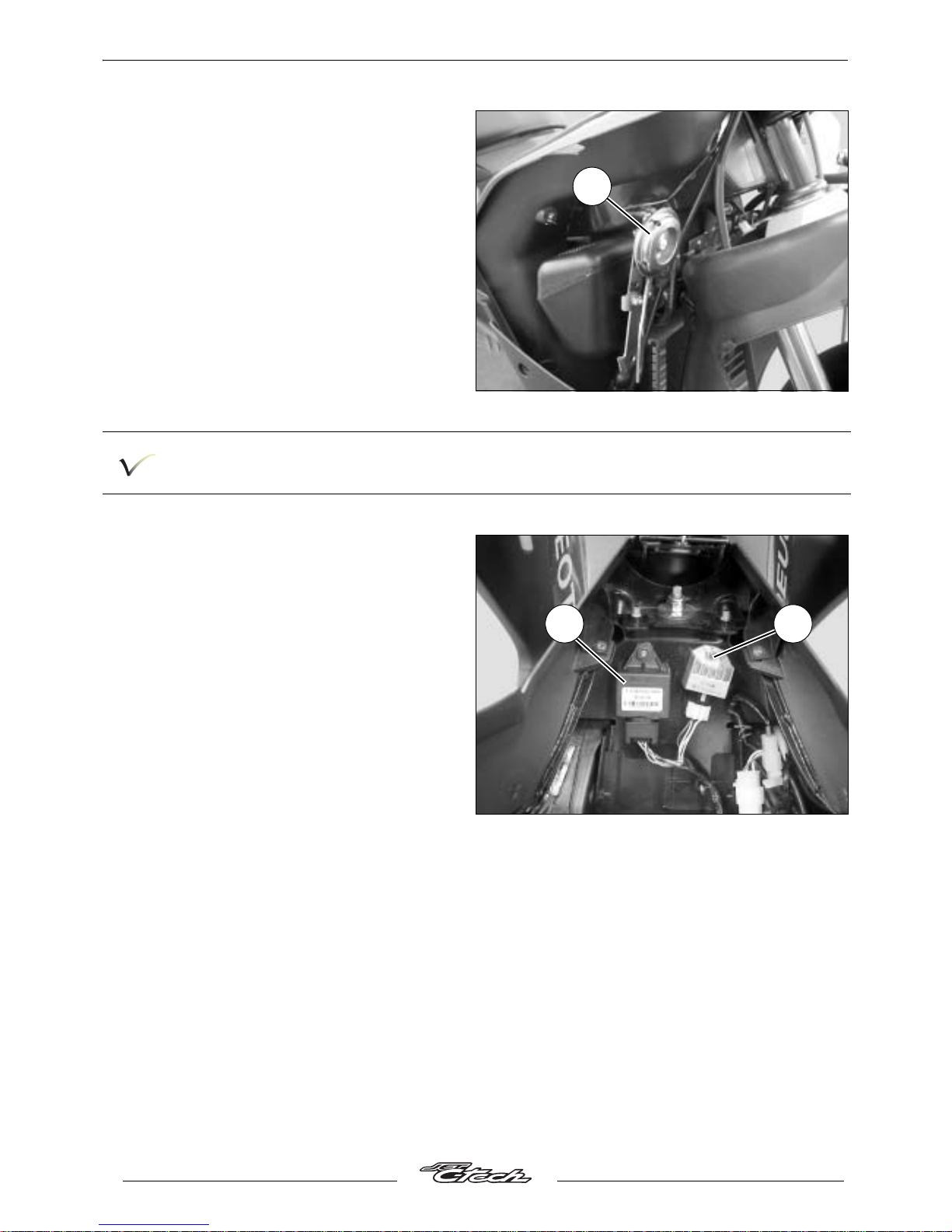
Removal of the horn.
- Remove the front upper shield panel (see
procedure 1).
- Removal of front lower shield panels (see
procedure 2).
- Remove the horn (1).
When refitting, locate the header tank positioning pins (A) and the window (B) in the rear shield
and in the radiator bracket.
Removal of the oil pump control unit.
Removal of the regulator.
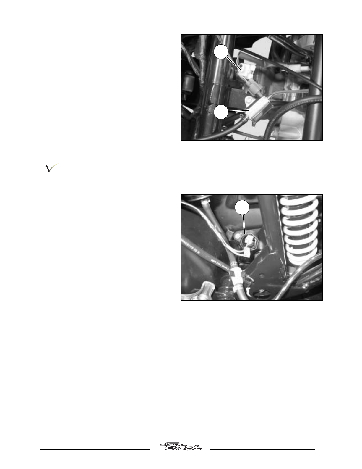
Removal of the engine temperature
sensor.
Removal of the oil pump.
- Remove the storage compartment (see
procedure 4).
- Remove.
• Control unit (1).
• Regulator (2).
1
1 2
Page 19
ELECTRIC COMPONENTS
17
Reproduction or translation, even partial, is forbidden without the written consent of Peugeot Motocycles
• Oil pump (3).
• The temperature sensor (4).
Refit a sensor quickly to prevent loss of coolant.
Removal of the high tension coil.
- Remove the footboard and the left tunnel (see
procedure 3)
- Disconnect the coil (1) and the spark plug
lead.
- Remove the high tension coil.
4
3
1
Page 20
PETROL CIRCUITS
18
Reproduction or translation, even partial, is forbidden without the written consent of Peugeot Motocycles
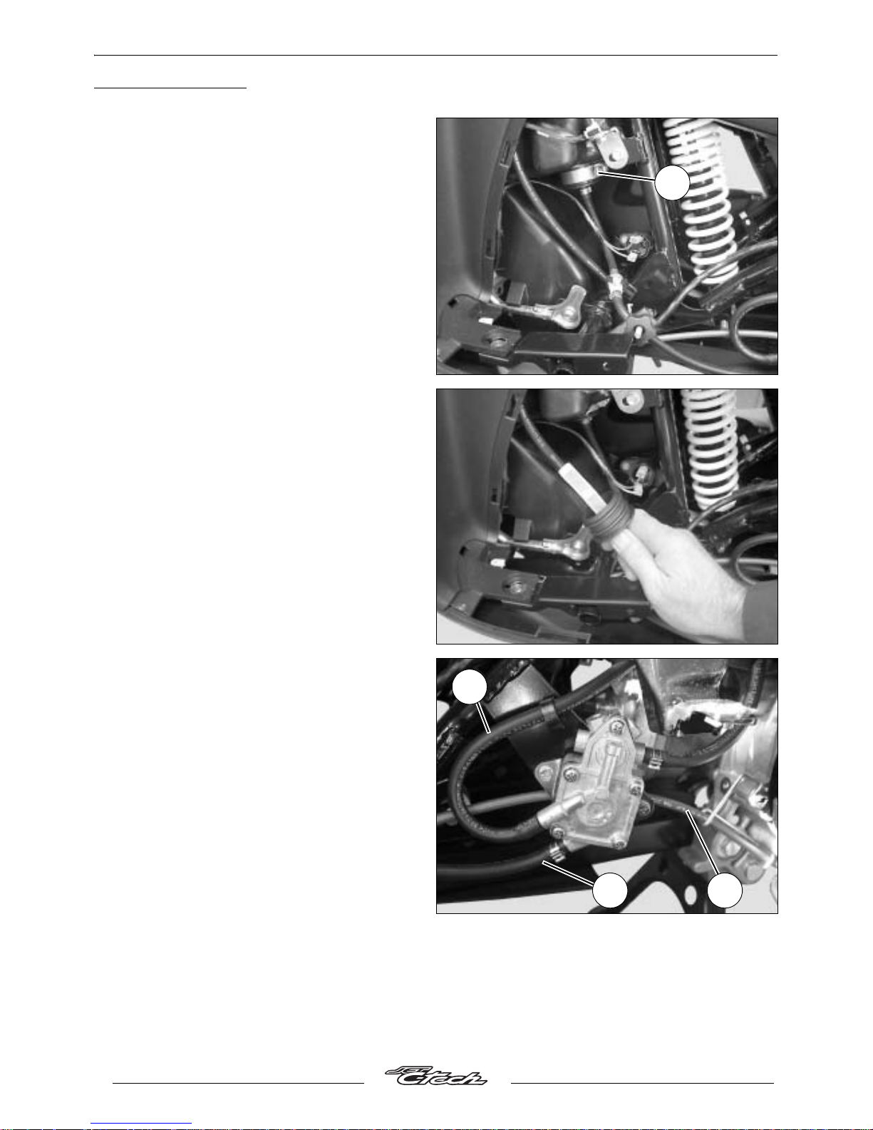
PETROL CIRCUITS
Removal of the fuel tank filter.
- Remove the footboard and the left tunnel (see
procedure 3).
- Empty the fuel tank by disconnecting a hose.
- Loosen the fuel filter collar (1).
- Remove the fuel filter.
- Clean or change the filter according to the
maintenance recommendations.
Removal of the fuel pump.
- Remove the footboard and the left tunnel (see
procedure 3).
- Put a hose clamp P/N 755996 on the fuel inlet
hose (1)
- Disconnect the 2 fuel hoses (1 and 3).
- Disconnect the vacuum hose (2).
- Remove the fuel pump (2 screw).
1
1
2
3
Page 21
PETROL CIRCUITS
19
Reproduction or translation, even partial, is forbidden without the written consent of Peugeot Motocycles
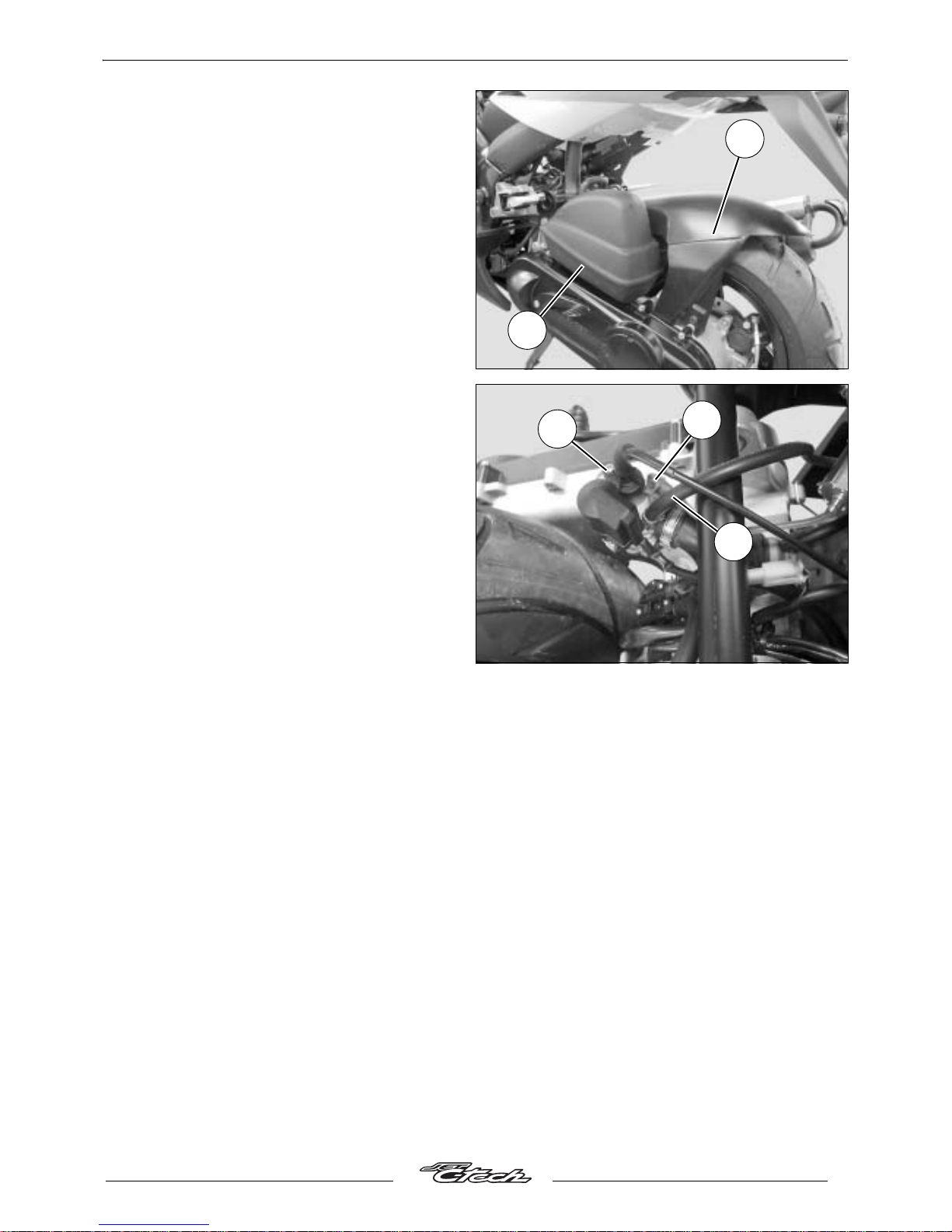
Removal of the carburettor.
- Remove the storage compartment (see
procedure 4).
- Remove the rear mudguard (1) 3 screws, 1 of
which is also used for the air filter).
- Disconnect the air pipe from tha air filter
housing (2).
- Remove the air filter (1 "click" collar).
- Disconnect the electric choke.
- Disconnect the separate lubrication hose (1).
- Remove the screw that secures the
carburettor chamber cap (2).
- Remove the carburettor and its cap and
needle valve.
- Disconnect the fuel supply hose (3) (1 "click"
collar).
1
2
3
1
2
Page 22
PETROL CIRCUITS
20
Reproduction or translation, even partial, is forbidden without the written consent of Peugeot Motocycles
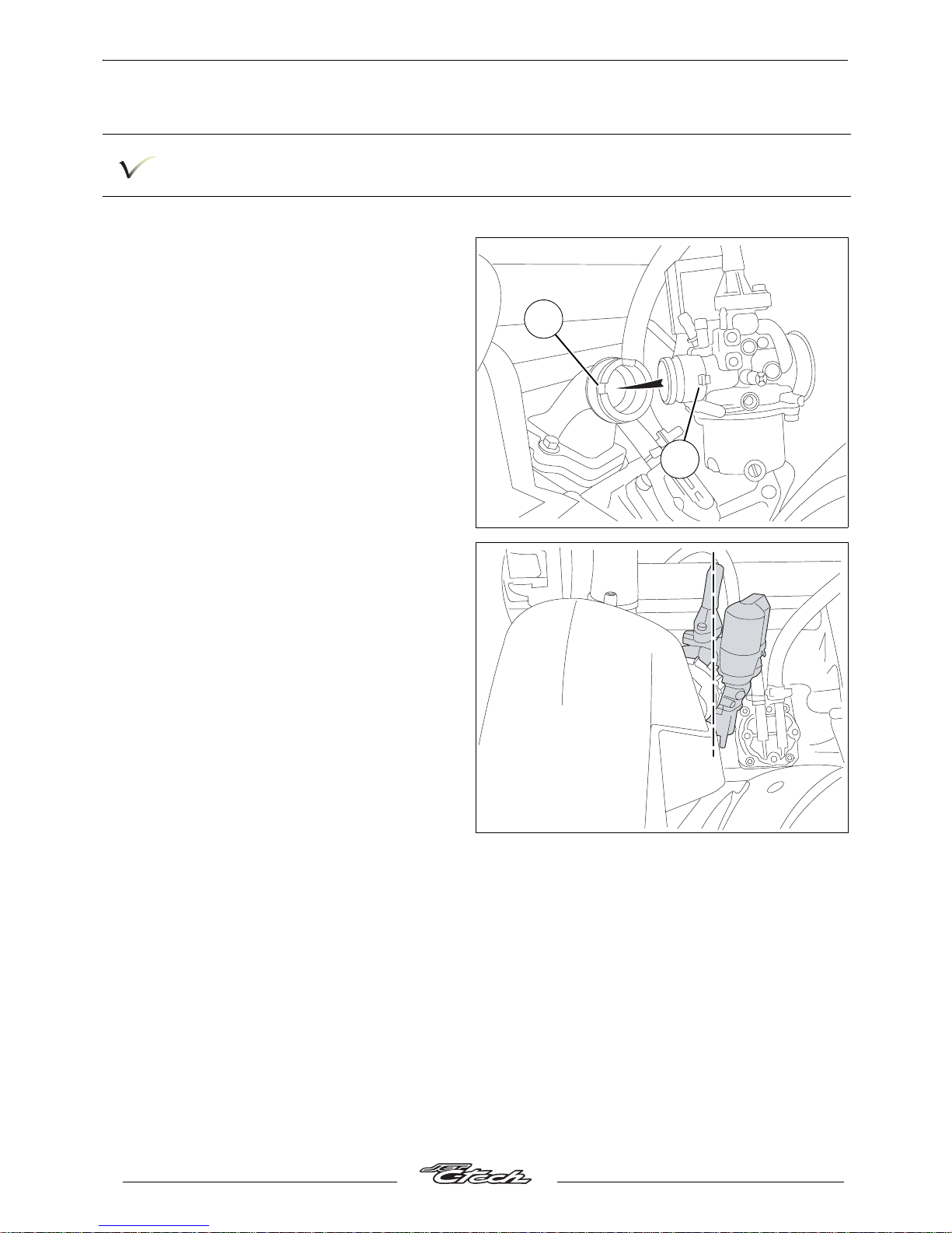
Procedure to position the carburettor.
To make sure the carburettor is correctly positioned, it is recommended that you follow the
following procedure.
- Fit the carburettor by making sure its pin is
correctly positioned (A) in the recess (B)
provided in the intake pipe.
- Click the collar.
- Fit the air filter on the carburettor.
- Fit and tighten the screw that secures the air
filter to make sur it is positioned.
- Clip theclick collar by making sure the
carburettor is level.
- Remove the air filter attachment screw.
- Connect the lubrication and fuel supply hose.
- Fit the slide valve and the chamber cap.
- Fit the rear mudguard.
- Fit the compartment.
A
B
Page 23
PETROL CIRCUITS
21
Reproduction or translation, even partial, is forbidden without the written consent of Peugeot Motocycles
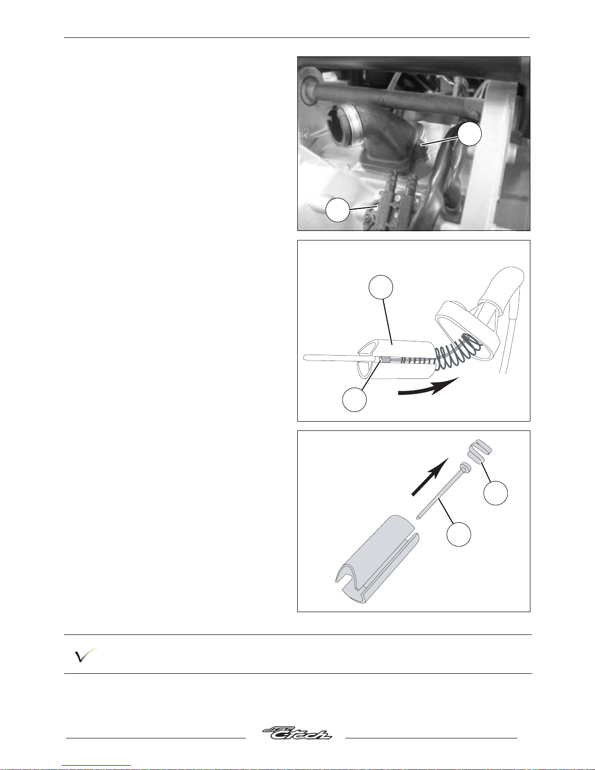
Removal of the inlet coupling and
valves.
- Disconnect the 2 ait supply hoses from the air
pump (1).
- Using a cutter, make a mark in the tamper
proof screw (2).
- Remove the 2 bolts.
- Remove the inlet coupling.
- Remove the reed valves and its gasket of
composite materials.
Removal of the throttle valve.
- Take out the throttle control cable (1) by
compressing the spring using the throttle
valve (2).
- Dismantle the valve equipped with its needle,
spring and carburettor chamber cap.
- Dismantle the needle (3) by pushing it out in
order to remove the clips (4).
The height oif the needle is factory set and cannot be modified.
2
1
2
1
4
3
Page 24
WORKING ON THE ENGINE WITHOUT REMOVING THE ENGINE
22
Reproduction or translation, even partial, is forbidden without the written consent of Peugeot Motocycles
WORKING ON THE ENGINE WITHOUT REMOVING THE ENGINE
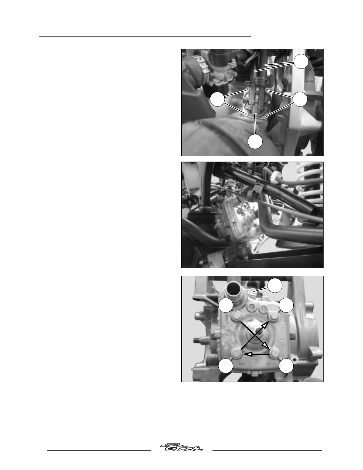
Removal of the air pump.
- Remove the rear mudguard.
- Remove the 4 screws (1) that secure the air
pump (2).
- Disconnect the 2 air hoses (3).
- Note: When re-installing, install the air pump
with its 2 guiding bushes and a new O-ring
slightly lubricated.
Removal of the cylinder / piston.
- Remove the storage compartment (see
procedure 4).
- Remove the footboard and the left tunnel (see
procedure 3).
- Remove the bottom panel.
- Disconnect the lower pump from the coolant
pump to drain the cooling system.
- Disconnect the coolant pipes from the cylinder
head and cylinder.
- Disconnect the temperature sensor.
- Disconnect the suppressor.
- Remove the spark plug.
- Remove the exhaust.
- Loosen the attachment screw (1).
- Slacken off the cylinder head/cylinder
4 mounting bolts in the order shown, in 2 or 3
stages.
- Remove the 5 bolts.
- Remove the cylinder head and its gasket.
- Remove the cylinder and its bottom seal.
2
1 1
3
1
A
B
D
C
Page 25
WORKING ON THE ENGINE WITHOUT REMOVING THE ENGINE
23
Reproduction or translation, even partial, is forbidden without the written consent of Peugeot Motocycles
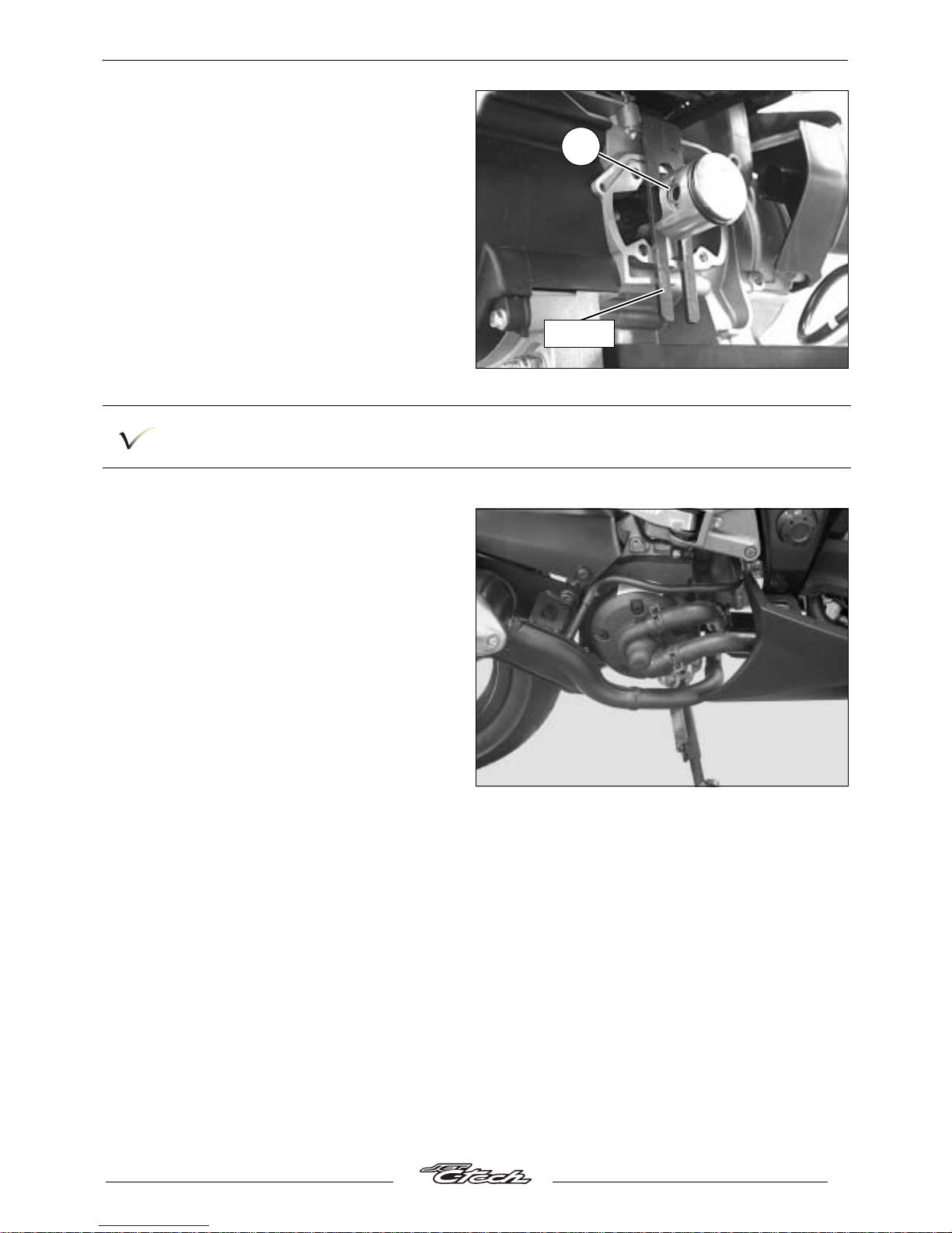
- Remove one of the spring clips (2) using pliers
P/N 752000.
- Remove the gudgeon pin.
- Remove the piston.
- Remove the needle bearing race from the
connecting rod end.
When refitting the cylinder, we recommend locking the piston using th e fork part number 756575
in order to facilitate assembly.
Removal of the water pump.
- Remove the exhaust.
- Disconnect the lower pump from the coolant
pump to drain the cooling system.
- Disconnect the upper hose.
- Remove the water pump.
2
756575
Page 26
MISCELLANEOUS OPERATIONS
24
Reproduction or translation, even partial, is forbidden without the written consent of Peugeot Motocycles
MISCELLANEOUS OPERATIONS
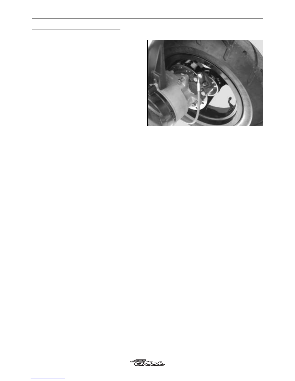
Removal of the rear brake pad.
- Remove the 3 lug studs of the rear wheel.
- Remove the caliper 2 fixing bolts.
- Remove the caliper from the brake disc.
- Remove the pins.
- Remove the brake pads.
Page 27

Page 28
P/N 758073
In our permanent concern to make improvements PEUGEOT MOTOCYCLES reserves the right to suppress,
modify, or add any reference mentioned.
DC/APV Printed in the E.U. 04/2005 (non contractual pictures)
 Loading...