

Page 1
Sales division
Technical network leadership
WORKSHOP MANUAL
-
Page 2

Workshop manual
Technical network leadership
Reproduction or transla tion, even partial, is for bidden without the written consent of Peugeot Motoc ycles
Page 3

TABLE OF CONTENTS.
TABLE OF CONTENTS.
TABLE OF CONTENTS. ...................................... ... ..........................................................................................1
PRODUCTS DANGER SYMBOLS USED......................................................................................................... 4
CHARACTERISTICS.........................................................................................................................................6
Engine........................................................................................................................................................6
Capacities..................................................................................................................................................6
Chassis......................................................................................................................................................7
Dimensions and weight............. ... .... ... .......................................................................................................7
Tyres..........................................................................................................................................................7
SERVICE SCHEDULE AND COMMISSIONING............................................................................................... 8
Check.........................................................................................................................................................8
Change ......................................................................................................................................................8
Check and lubricate ............... ... ... .... ...................................... .... ... ... ... .......................................................9
Reading the ECU fault codes.... ... .............................................................................. ... ... .... ... .. .................9
Test machine .............................................................................................................................................9
Time required for maintenance................................. .... ... ....................................... ... ... ... .... ......................9
Battery preparation (Except battery without maintenance)*.....................................................................10
Checks before handing over to the customer ..........................................................................................10
SPECIAL IMPORTANT POINTS..................................................................................................................... 11
Oil and fuel...............................................................................................................................................11
Starting up after overhauling the engine..................................................................................................11
Electricity..................................................................................................................................................11
Special features ..................................................... ... .... ... ... ....................................... ... ...........................11
TIGHTENING TORQUES. ....................... ... ... ... .... .......................................... .................................................12
Engine part...............................................................................................................................................12
Body panels .............................................................................................................................................13
Cycle part.................................................................................................................................................13
Standard ..................................................................................................................................................13
SPECIAL TOOLS ............................................................................................................................................ 14
ELECTRICITY..................................................................................................................................................15
4 stroke indirect injection system functional diagram...............................................................................15
ABS/MBS system schematic diagram .....................................................................................................16
Fuses and energy distribution..................................................................................................................17
Reproduction or translation, even partial, is forbidden without the written consent of Peugeot Motocycles
1
Page 4

TABLE OF CONTENTS.
LOCATION OF COMPONENTS...................................................................................................................... 18
BODY PANELS ............................. .................................................................................................................. 19
Location of body components..................................................................................................................19
Body component sequence of disassembly.............................................................................................20
Removal of the storage compartment........................................................... ...........................................21
Removal of a RH or LH side cover ..........................................................................................................21
Removal of the tank covers .......................... ... ... ... ... ....................................... ... .... ... ... ...........................22
Removal of a RH or LH footboard.... ... ... ... .... ... ........................................................................................23
Removal of the front shield panel .......................... ....................................... ... ... .... ... ..............................24
Removal of the rear shield panel ..... ... ... ... .... ... ....................................... ... ... ... ........................................25
Removal of the dirt shield ................................ ... ... ....................................... ... ... .... ... ... ... ........................25
Removal of the instrument cluster ................... ... ....................................... ... ... ... .... .................................26
Removal of the battery holder.......................................... ... ... .... ... ....................................... ... .................26
SERVICE OPERATIONS............... ... .......................................... .......................................... ........................... 27
Changing the engine oil and replacing the oil filter ..................................................................................27
Draining the relay box............................................ ... .... ...................................... .... ... ... ... ... .....................29
Replacing the air filter ..............................................................................................................................30
Removal of the transmission air filter.......................................................................................................32
Changing the drive pulley bearings..........................................................................................................32
Removal of the spark plug ........... .... ... ... ... .... ...................................... .... ... ... ...........................................33
Draining the cooling circuit........ ... .... ... ....................................... ... ... ... .... ... ... ...........................................33
Installing the valve clearance........................... ........................................................................................34
Replacing the brake pads ........................................................................................................................36
Front brake........................................................................................................................................................36
Rear brake................. ... ....................................................................................................................................36
Checking the brake fluid level.......................................... ........................................................................40
SERVICING THE ABS/MBS SYSTEM............................................................................................................41
Reminder .................................................................................................................................................41
Removal of the brake modulator.. ....................................... ... .... ... ... ....................................... ... ..............41
Re-installing the modulator ......................................................................................................................42
Bleed procedure.......................................................................................................................................43
Draining the rear brake circuit...........................................................................................................................43
Bleeding the assistance circuit..........................................................................................................................45
Draining the front brake circuit..........................................................................................................................46
2
Reproduction or translation, even partial, is forbidden without the written consent of Peugeot Motocycles
Page 5

TABLE OF CONTENTS.
MISCELLANEOUS OPERATIONS ................................................................................................................. 49
Procedure for reducing the fuel circuit pr es su re ........................................ ...................................... ........49
Checking fuel pressure ............. ... .... ... ... ... ....................................... ... .... ... ... ...........................................50
Removal of the fuel pump................................................................................ ... .... ... ... ...........................51
Removal of the fuel gauge............................................................................... ... .... ... ... ...........................52
Removal of the throttle box.............................................................................. ... .... ... ... ...........................53
Removal of the lambda sensor ........ ...................................... .... ... ... ... ....................................... . .............53
Removal of the regulator. .... ...................................... .... ... ... ... ....................................... ... .... . ...................54
Removal of the radiator....... ...................................... .... ... ... ... ....................................... ... ........................55
Removal of the engine mounting assembly............................................................... ... ... .... ... ... ... ...........56
Removal of the engine........................................... ... .... ... ....................................... ... ... ... .... . ...................58
Removal of the fork................ ... ....................................... ... ... .... ... ...........................................................62
Replacing the bearings of the steering system........................................................................................62
Steering system tightening method........................... .... ...................................... .... ... ... ... ........................64
Reproduction or translation, even partial, is forbidden without the written consent of Peugeot Motocycles
3
Page 6
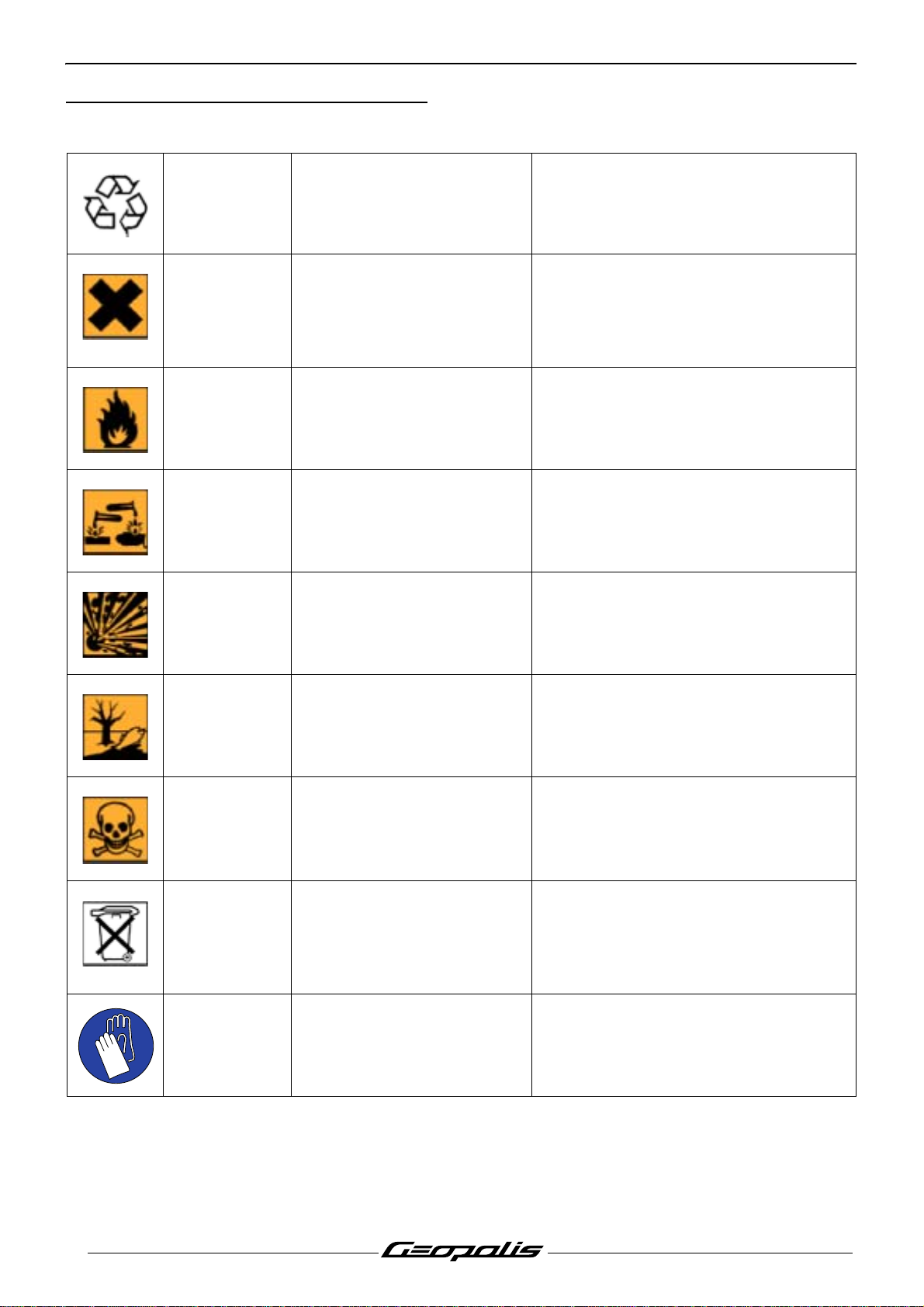
PRODUCTS DANGER SYMBOLS USED
PRODUCTS DANGER SYMBOLS USED
Protection of individuals and of the environment.
Möbius band Recyclable
The product can irritate the
Irritant
Flammable The product is flammable
Corrosive
skin, eyes and repiratory
organs
The product can damage living
tissues or other surfaces
Means that the product or the package
can be recycled. However, this does not
guarantee that the product will be
recycled.
Avoid contact with the skin and clothes.
Wear gloves, safety glasses and
appropriate clothes such as a cotton
overall. Do not breath fumes. If in contact,
wash thoroughly with water.
Keep it away from any flame or heat
source (barbecue, radiator, heating
device, etc.). . . . Do not leave the product
in the sun.
Avoid contact with the skin and clothes.
Wear gloves, safety glasses and
appropriate clothes such as a cotton
overall. Do not breath fumes.
Explosive
Hazardous to
the environment
Toxic
Do not throw
away into a
garbage can
Compulsory
gloves
The product can explode under
certain circumstances (flame,
heat, impact, friction)
The product affects fauna and
flora. Do not dump it in
garbage cans, sinks or nature.
The product can seriously
affect health if it is inhaled,
ingested or in contact with skin
One of the product's
component is toxic and can be
hazardous to environment. Ex.
Used batteries
Operation that can be
dangerous for people
Avoid impacts, friction, sparks and heat.
The ideal solution is to bring this product
to your nearest household waste recycling
centre.
Avoid direct contact with body even by
inhalation. If you feel unwell, seek medical
advice immediately.
This symbol informs the consumer that the
used product shall not be thrown away into
a garbage can, but shall be brought back
to the merchant or dropped at a specific
collection point
People's safety can be seriously affected if
the recommendations are not fully
respected.
4
Reproduction or translation, even partial, is forbidden without the written consent of Peugeot Motocycles
Page 7
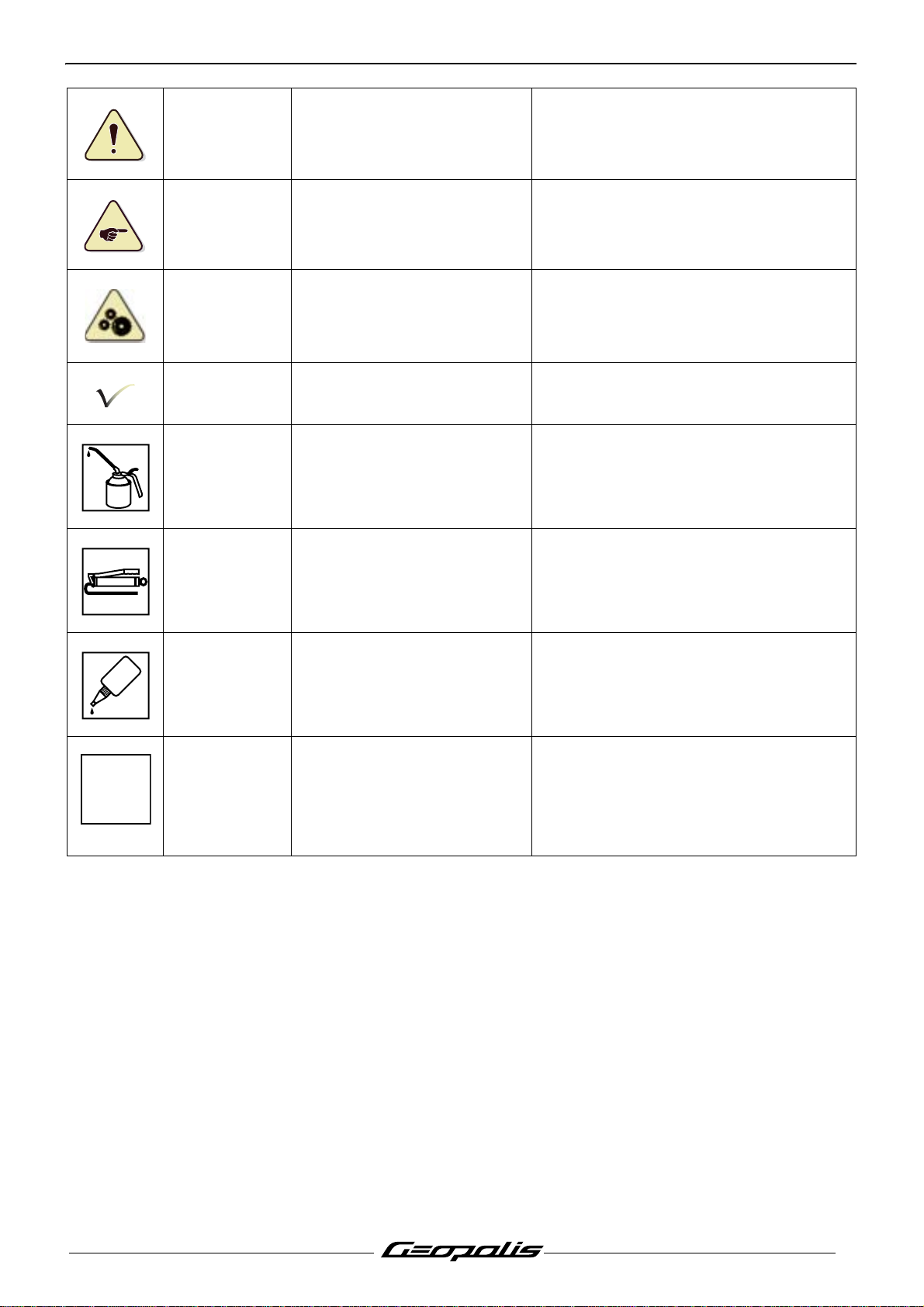
PRODUCTS DANGER SYMBOLS USED
N
People's safety
Important
Good operating
condition of the
vehicle
Note Operation that can be difficult
Lubricate
Grease
Operation that can be
dangerous for people
Operation that can be
hazardous to the vehicle
The operation must be carried
out in strict compliance with the
documents
Lubricate the parts to be
assembled
Grease the parts to be
assembled
People's safety can be seriously affected if
the recommendations are not fully
respected.
Indicate the specific procedures that shall
be followed in order not to damage the
vehicle
Serious damage to the vehicle and in
certain cases a cancellation of the
warranty can be involved if the
recommendations are not fully respected.
Indicate a note which gives key
information to make the procedure easier
Indicate the specific procedures that shall
be followed in order not to damage the
vehicle.
Indicate the specific procedures that shall
be followed in order not to damage the
vehicle.
GLUE
Glue Glue the parts to be assembled
New part Use a new part
Indicate the specific procedures that shall
be followed in order not to damage the
vehicle.
Indicate the specific procedures that shall
be followed in order not to damage the
vehicle.
5
Reproduction or translation, even partial, is forbidden without the written consent of Peugeot Motocycles
Page 8
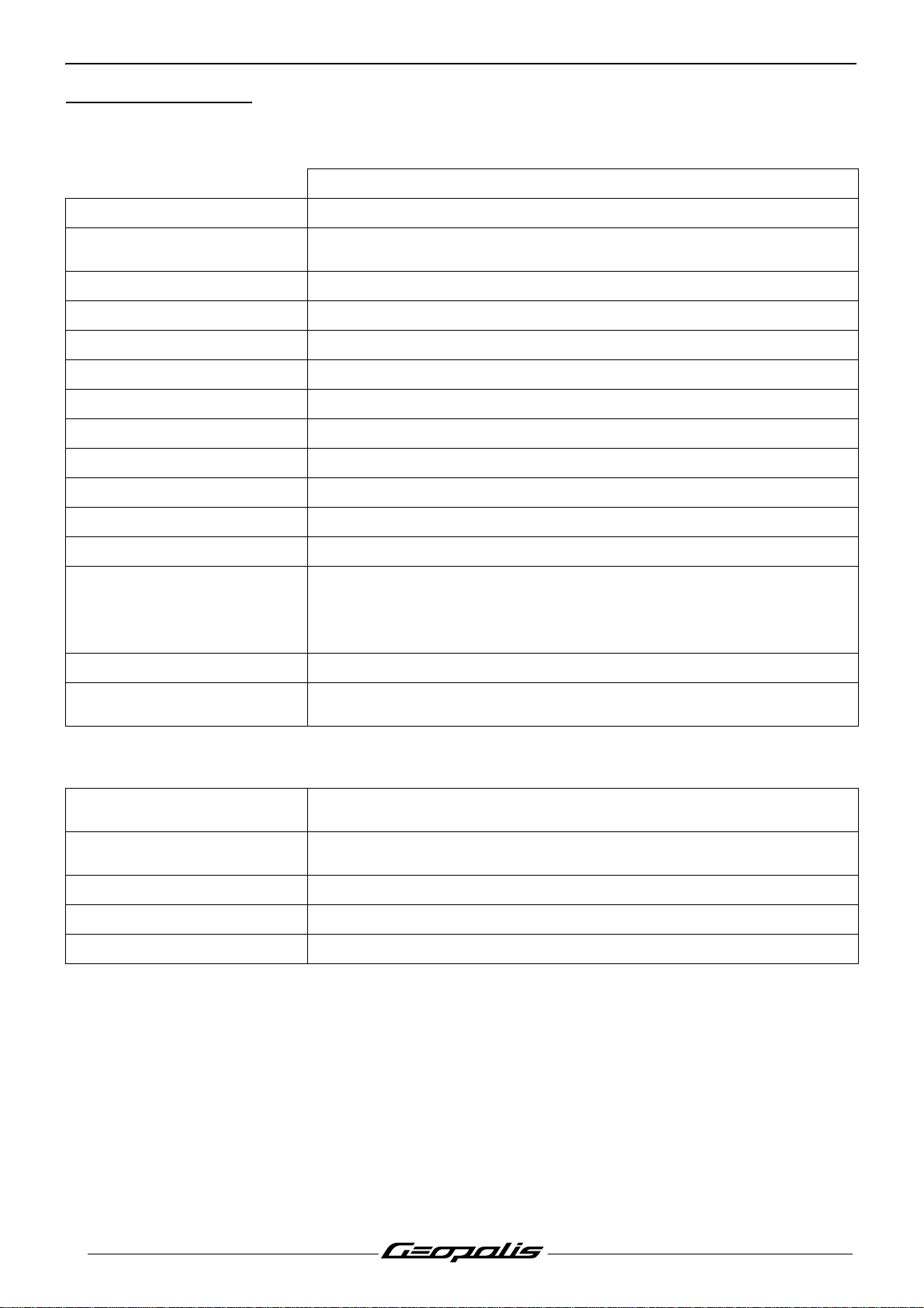
CHARACTERISTICS
CHARACTERISTICS
Engine
Marking M564M
400 cc
Type
4 valves per cylinder with chain driven overhead camshaft
4-stroke single-cylinder
Cooling Liquid
Bore x stroke 85.8 x 69 mm
Cubic capacity 399 cc
Max. power output 25 kW at 7500 rpm
Max. torque rating 5500 rpm
Lubrication Trochoidal pump
Transmission By 2 variable pulleys and V-type belt
Clutch Centrifugal automatic
Exhaust Catalytic
Starter motor Mitsuba 900 W
1 spark plug
Spark plug
NGK CR7EKB
Electrode gap
0.7-0.8 mm
Magneto flywheel Mitsuba 350 W
Fuel supply
Indirect electronic injection
Magneti-Marelli
Capacities
Engine oil
Relay box oil
Coolant 1.4 l Peugeot coolant part number 754614.
Fork oil 212 cc per tube (Esso Univis 46 or Agip HLift 46)
Fuel tank 13.2 l / Version ABS 10.5 l
1.7 l SAE 5W40.
Minimum grade: API SJ.
0.25 l SAE 80W90.
Minimum grade: API GL4.
6
Reproduction or translation, even partial, is forbidden without the written consent of Peugeot Motocycles
Page 9
CHARACTERISTICS
Chassis
Chassis Double cradle out of high-resistance steel tube
Front suspension Hydraulic telescopic fork. Ø37 mm
Travel 100 mm
Rear suspension 2 adjustable combined spring hydraulic shock absorbers
Travel 100 mm
Dimensions and weight
Overall length
Width at handlebar
Height.(without rear-view
2180 mm
755 mm
1486 mm
mirrors)
Wheelbase 1527 mm
Ground clearance
Saddle height
Unladen weight
Tyres
157 mm
805 mm
200 kg.
Front wheel rim 16 inch aluminium alloy
Front tyre 110/70 - 16
Front tyre pressure 2.2 bars
Rear wheel rim 14 inch aluminium alloy
Rear tyre 150/70 - 14
Rear tyre pressure 2.4 bars
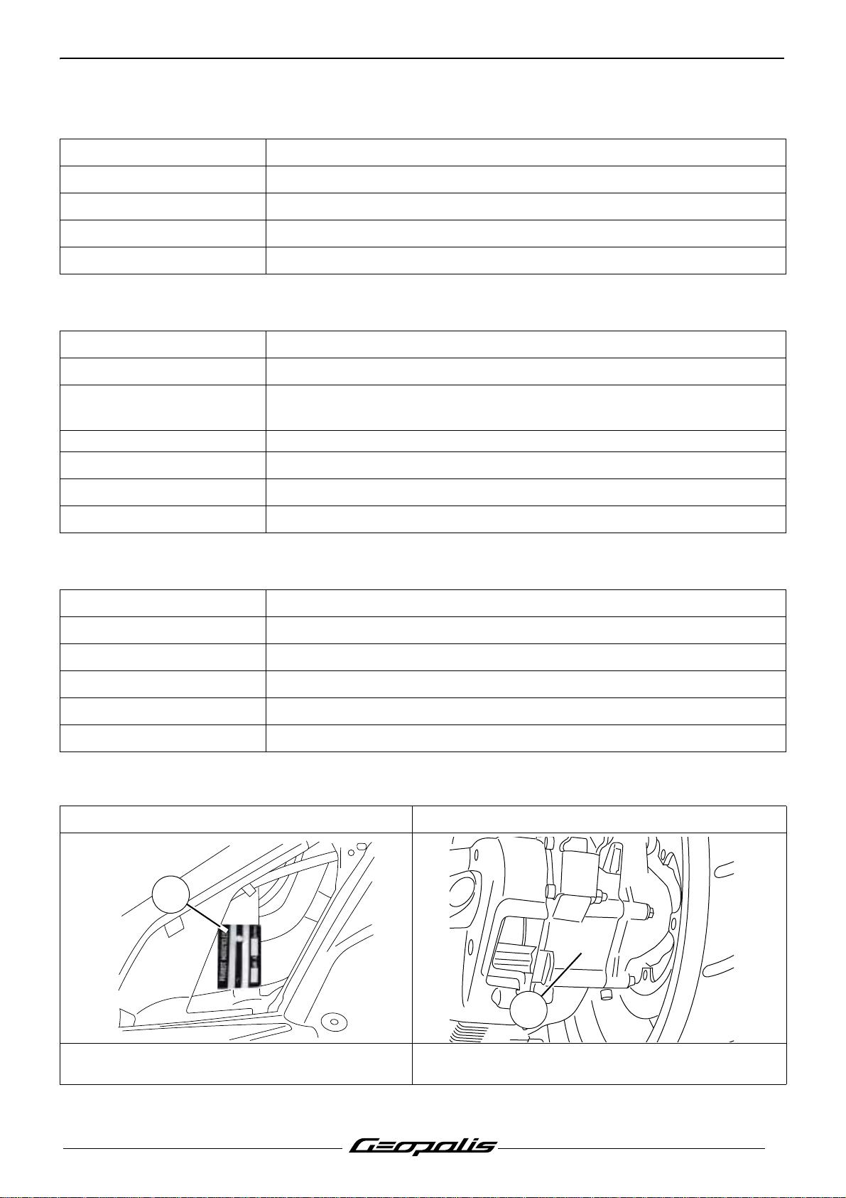
Chassis markings Engine marking
1
M461M
xxxxxxxxxx
2
1. Manufacturer's plate.(Left side)
- VIN number of the RH side of the vehicle
Reproduction or translation, even partial, is forbidden without the written consent of Peugeot Motocycles
2. Engine number
7
Page 10
SERVICE SCHEDULE AND COMMISSIONING
SERVICE SCHEDULE AND COMMISSIONING
Heavy duty servicing applies to vehicles used under rugged operating conditions: door-to-door
deliveries, intensive urban use (courier), short journeys with engine cold, dusty areas, ambient
temperature over 30°C.
Service operations
Heavy duty servicing 500 kms
Check
1000 kms or
1 months
Every
5000 kms
Every
2500 kms
Every
10000 kms
Every
5000 kms
Every
20000 kms
Every
10000 kms
Throttle cable play C C C C
Steering column play C C C C
Operation of electrical equipment C C C C
Condition of front and rear brake
hydraulic controls
CCCC
Condition of petrol pipes C C C C
Condition of oil pipes C C C C
Tyre pressures C C C C
Tyre condition, pressure and wear C C C
Condition of the front suspension C C C C
Condition of the rear suspension C C C C
Brake fluid level C C C C
Battery electrolyte level * C C C C
Coolant level C C C C
Engine oil level C
Valve clearances C
Transmission air filter N N
Intake silencer drain N N N N
Tightening the engine mounting and
linkrod
CCC
Tightness of nuts and bolts C C C C
Change
Spark plug R R
Inlet silencer/air filter N N
Front brake pads C C C
Rear brake pads C C C
Drive pulley bearings and guides C C
Transmission belt R R
Belt anti-flapping roller C C
Engine oil R R R
Engine oil filter R R R
Relay box oil R C C
Brake fluid and coolant Once every 2 years
8
Reproduction or translation, even partial, is forbidden without the written consent of Peugeot Motocycles
Page 11
SERVICE SCHEDULE AND COMMISSIONING
Service operations
Heavy duty servicing 500 kms
Check and lubricate
1000 kms or
1 months
Every
5000 kms
Every
2500 kms
Every
10000 kms
Every
5000 kms
Every
20000 kms
Every
10000 kms
Drive pulley/Movable face C C
Driven pulley: Movable face C C
Driven pulley caged needle bearing G G
Reading the ECU fault codes
Injection and ABS/MBS system* C C C C
Test machine
On road (at least 2 km) C C C C
Time required for
maintenance
Code 9100 9300 9400 9600
Time required for maintenance 1.0 0.8 2.2 2.5
C: Check.
N: Clean.
R: Change.
G: Check and lubricate.
* Depending on equipment.
# Change if necessary.
Reproduction or translation, even partial, is forbidden without the written consent of Peugeot Motocycles
9
Page 12

SERVICE SCHEDULE AND COMMISSIONING
Battery preparation (Except battery without maintenance)*
Remove the battery.
Remove the 6 filler caps and the vent plug.
Fill all the battery cells with electrolyte to the upper level shown on the battery "UPPER LEVEL".
Electrolyte: (35% sulfuric acid = 1.28g/cm3). 1 litre can P/N 752740. 5 litre can P/N 752741.
Leave the battery to stand for around half an hour.
Top up if necessary.
Charge the battery for at least 2 hours with a current of 1.4 A.
Refit the battery and connect the vapour vent pipe.
Connect the red wire lug to the battery's + terminal, and the green wire lug to the battery's - termin al.
Then, the battery level should be topped up if necessary, after fully charging, using distilled water only.
Checks before handing over to the customer
Check the wheel nuts are tight.
Check nuts and bolts are tight.
Check brake adjustment and efficiency.
Check the tyre pressures cold.
Check operation of the lights, flashers, horn, and brake light.
Check the different warning lights work.
Carry out a road test.
Depending on equipment.
10
Reproduction or translation, even partial, is forbidden without the written consent of Peugeot Motocycles
Page 13
SPECIAL IMPORTANT POINTS
Oil and fuel
This engine is designed to run on 95 or 98 unleaded fuel only.
Fuel pipes must absolutely be changed if there are any signs of wear, cracks, etc.
The clips are specific, they must always be changed each time they are removed and replaced
with new genuine parts clips.
Petrol is highly inflammable, do not smoke in the working area and a void proximity to flames or
sparks.
Before carrying out any work, leave the engine to cool for at least 2 hours.
SPECIAL IMPORTANT POINTS
Starting up after overhauling the engine
When starting the engine hot or cold do not accelerate.
Check the coolant level in the header tank.
After road-testing the machine, check there are no fault codes left in the ECUs (using the diagnostic
tool).
Electricity
All components of the electrical system are powered with 12 volts DC.
The battery must not be disconnected while the engine is running and the voltage must be at least
7 volts for the ECU to function and enable engine starting.
Special features
An immobiliser built in the ECU provides the antitheft function by means of a transponder.
The ECU has a diagnostic function which via the instrument cluster LED or the diagnostic tool, enables
reading of the faults in the memory.
Reproduction or translation, even partial, is forbidden without the written consent of Peugeot Motocycles
11
Page 14

TIGHTENING TORQUES.
TIGHTENING TORQUES.
Engine part
Drive pulley 17 m.daN
Driven pulley 9.6 m.daN
Clutch plate and shoes 7 m.daN
Belt anti-flapping roller 1.8 m.daN
Transmission cover;
• 6 mm diameter screw
• 8 mm diameter screw
Relay box cover 2.5 m.daN
Relay box drain plug 1.5 m.daN
Flywheel magneto cover 1.2 m.daN
Stator 1 m.daN
Engine speed sensor 0.5 m.daN
Rotor 12 m.daN
Freewheel 1.4 m.daN
Starter motor 1.2 m.daN
Automatic tensioner 1.2 m.daN
Automatic tensioner plug 0.5 m.daN
Spark plug 1.2 m.daN
Camshaft gear 3.2 m.daN
Chain tensioner 1.2 m.daN
Camshaft stop plat 0.5 m.daN
Cylinder head. (Guide pins Procedure
Cylinder head bolts and nuts 1.2 m.daN
Cylinder head cover 0.8 m.daN
Inlet manifold 1.2 m.daN
Engine temperature sensor 1.1 m.daN
Injection ECU 1.2 m.daN
Injection rail 0.3 m.daN
Oil pressure switch 1.2 m.daN
Oil pump 0.6 m.daN
Oil filter 1.4 m.daN
Oil pump cover 0.9 m.daN
Crankcase 1.2 m.daN
Conrod and crankshaft assembly gear 1.1 m.daN
Balancing shaft 2.8 m.daN
Engine drain plug 2.5 m.daN
Water pump cap 0.4 m.daN
Water pump impeller 0.5 m.daN
Cooling system bleeder screw 0.3 m.daN
1.2 m.daN
2.4 m.daN
12
Reproduction or translation, even partial, is forbidden without the written consent of Peugeot Motocycles
Page 15
TIGHTENING TORQUES.
Body panels
Front mudguard 0.8 to 1.2 m.daN
Handlebar cover 0.2 to 0.4 m.daN
Front shield panels 0.2 to 0.4 m.daN
Rear shield 0.2 to 0.4 m.daN
Bottom panel 0.2 to 0.4 m.daN
Floor panel 0.4 to 0.6 m.daN
Saddle storage compartment 0.8 to 1.2 m.daN
Rear panels 0.2 to 0.4 m.daN
Grab handle 2 to 2.5 m.daN
Rear mudguard 0.4 to 0.6 m.daN
Cycle part
Front wheel spindle 6.5 m.daN
Rear wheel bolt 2.5 m.daN
Rear wheel spindle nut 13.5 m.daN
Linkrod to engine pivot 8 m.daN
Linkrod to frame pivot 8 m.daN
Linkrod connecting pin 8 m.daN
Linkage torque arms 3.8 m.daN
Shock absorber top mount 4.5 m.daN
Shock absorber bottom mount 4.5 m.daN
Exhaust to cylinder head mounting nut 2.2 m.daN
Exhaust to casing mounting bolt 2.2 m.daN
Exhaust system strap 1.8 m.daN
Exhaust clamp 1.8 m.daN
Centre stand holder 2.2 m.daN
Suspension arm 2.8 m.daN
Lambda sensor 4.5 m.daN
Upper cone (in 2 operations) 4/2.2 m.daN
Upper cone locknut Hand tightened
Steering locknut 7.5 m.daN
Front brake caliper 2.5 m.daN
Rear brake caliper 2.5 m.daN
Front brake disc 3 m.daN
Rear brake disc 3 m.daN
Handle bar 4 m.daN
Standard
Nut and bolt 5 mm diameter 0.6 m.daN
Nut and bolt 6 mm diameter 1 m.daN
Nut and bolt 8 mm diameter 2.2 m.daN
Nut and bolt 10 mm diameter 3.5 m.daN
Nut and bolt 12 mm diameter 5.5 m.daN
Reproduction or translation, even partial, is forbidden without the written consent of Peugeot Motocycles
13
Page 16
SPECIAL TOOLS
SPECIAL TOOLS
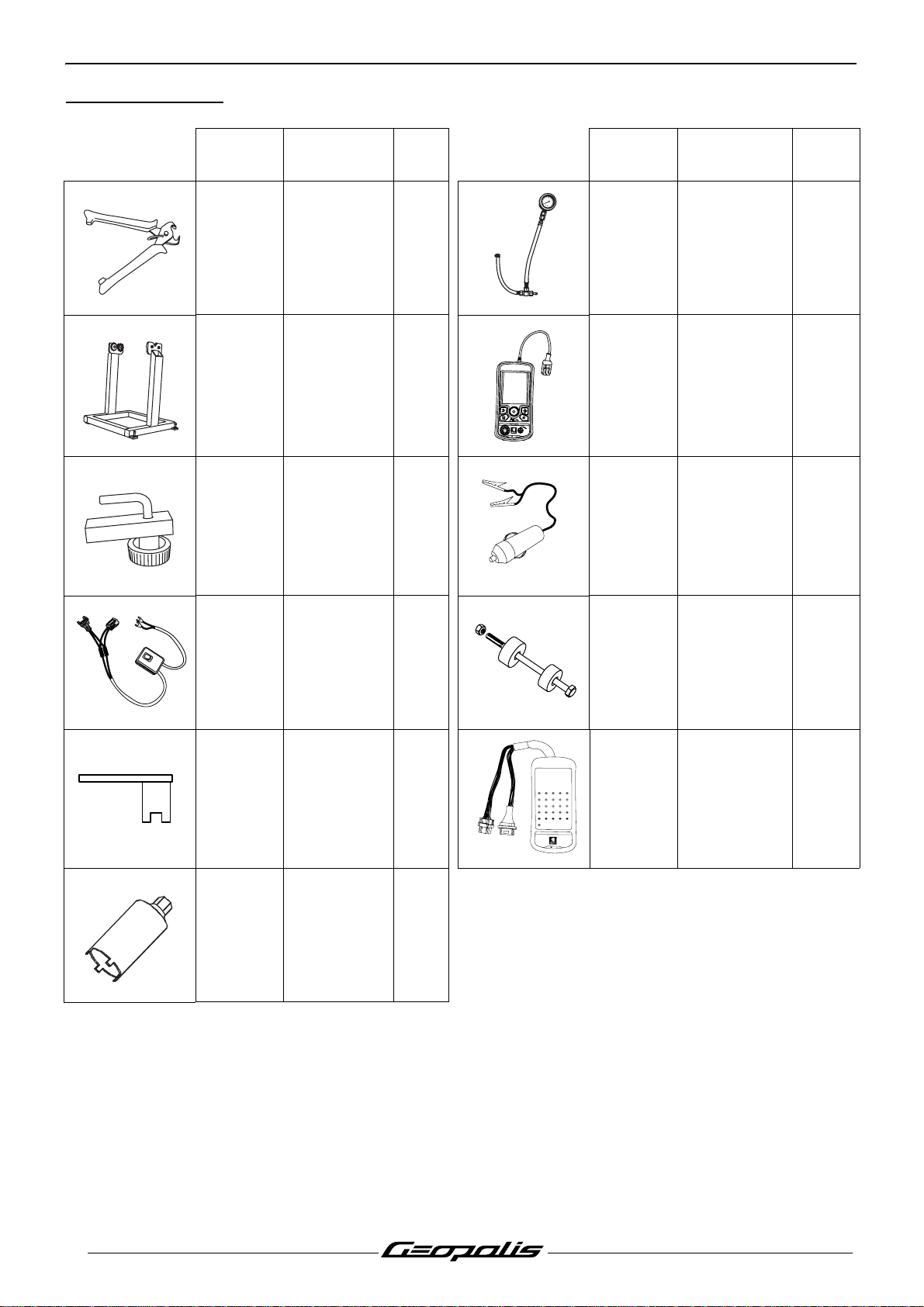
Tool N° Designation
750539
Tie-wrap
pliers
Used
with
Tool N° Designation
4
6
2
8
0
1
0
b
a
r
757877
Balance
754278
support with
pins Ø15 and
Ø17 mm
OK
TEP 2005
test
xxo
by
758358 TEP 2005
755996 Hose clamp 758585
Used
with
Pressure
gauge
Power supply
cable tool
756017
756715
(*)
757860 Steering tool
(*) New or modified tool.
Fuel injector
power supply
harness
Tank gauge
spanner
Steeing head
758810
cup
installation
tool
432
1
9208197186
17516
24122311221021
26
BM 2005
t
e
s
t
xxo
b
y
151413
25
758924
24 way
terminal block
14
Reproduction or translation, even partial, is forbidden without the written consent of Peugeot Motocycles
Page 17
ELECTRICITY
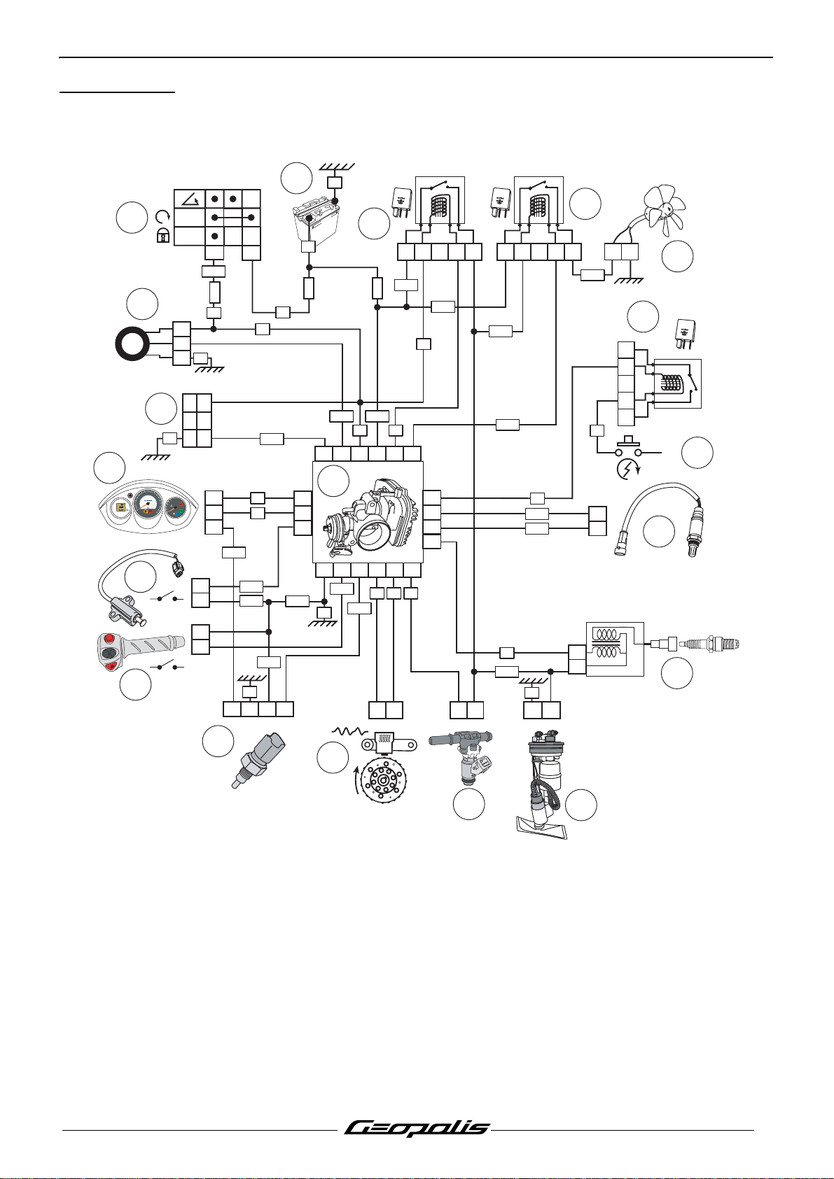
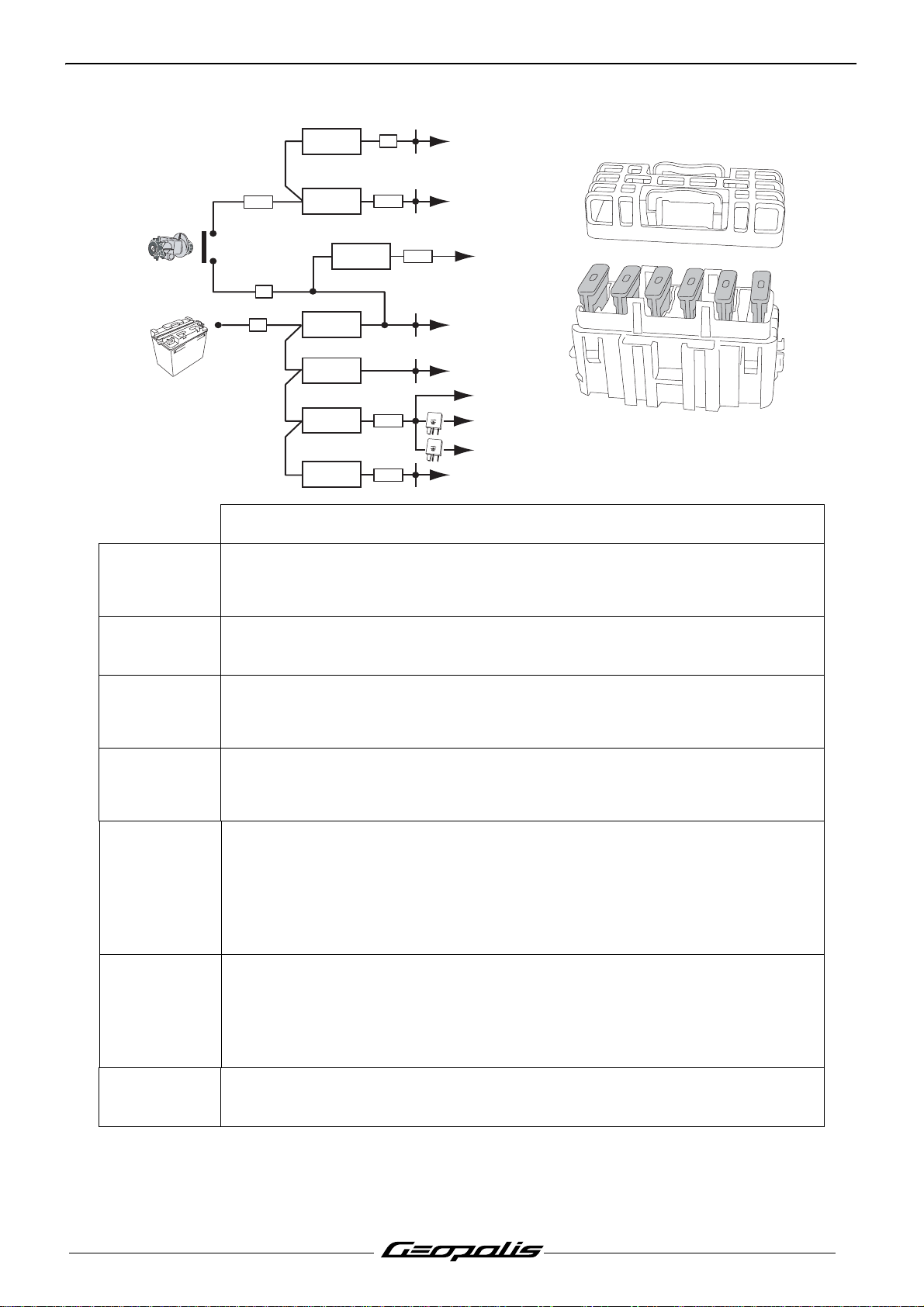
4 stroke indirect injection system functional diagram
ELECTRICITY
16
PEUGEOT
13
K
m
M
H
rs
18
14
40
0
2
17
ON
OFF
7,5A
1
3
2
F5
VE
RG-NR
NR
12
6
3
30A
F1a
RG
NR
VE
L
E
V
L
E
E
L
V
R
E
E
P
R L
P
E
U
W
O
L
-
RG
15A
F2
11
1
2
V
2
5
A
12345
GR-RG
GR-RG
NR
1
2
V
25
A
21345
VE-NR
10
VI-BA
12
3
9
8
1
2
V
- 2
5A
2
4
15
A3
GR-RGMR-BA
VE
B1A1
BA-NR
BCNR
VI-NR
82420716 5 6
80
100
0
6
50
6
120
0
40
70
30
8
0
140
20
120
9
0
10
1
80
160
0
0
0
40
K
m
/
h
BE
8
BA
7
11
RG-BA
1
1
17
18
4
11
22
VI
BA-VE
BE-NR
1
5
VI
+
7
1
2
6
15 1413926 12
1
0
2
1
1
2
0
1
VE-NR
GR-VE
VE
GR-VE
GR-VE
GR-VE
RG MR OR
BA-BE
VE
JN
VE-NR
VE
1
2
2
1
21
2
1
R
5
19
2
1. Injection ECU.
2. Engine speed and position sensor.
3. Petrol injector.
4. Fuel pump.
5. Ignition coil.
6. Lambda sensor.
7. Starter motor switch.
8. Starter motor relay.
9. Cooling fan.
10. Fan relay.
Reproduction or translation, even partial, is forbidden without the written consent of Peugeot Motocycles
3
4
11. Injection relay.
12. Battery.
13. Ignition switch.
14. Transponder antenna.
15. Diagnostic plug.
16. Instrument panel.
17. Kickstand switch.
18. Emergency stop switch
19. Engine temperature sensor.
15
Page 18
ELECTRICITY
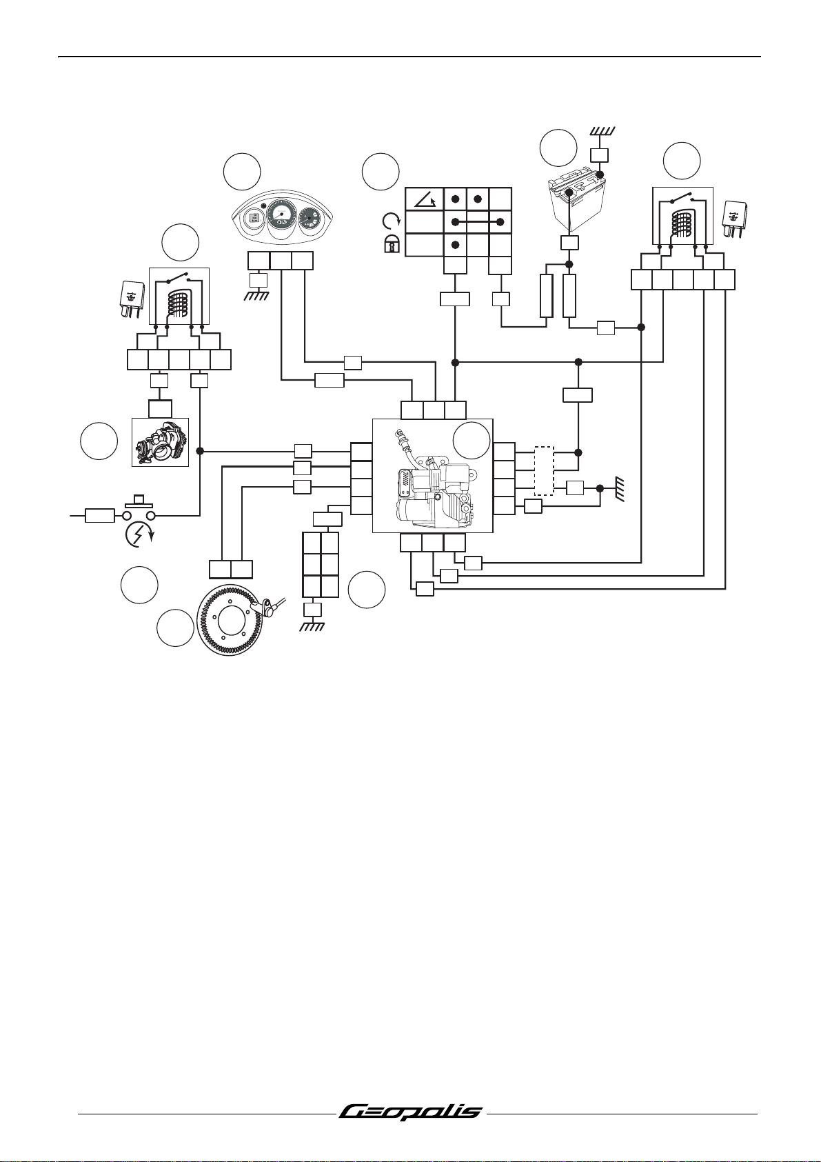
ABS/MBS system schematic diagram
8
JN/VE
1
2
V
2
5
A
START
6
24
3
10
80
100
60
5
0
60
120
0
4
70
0
3
40
80
140
20
120
9
Km
0
20
M
10
100
80
160
H
r
s
0
40
K
m/h
PEUGEOT
7
51417
VE
1
VI
2345
VI
MR/BA
GR
4
ON
OFF
6
RG/NR
RG
3
F1a 30A
-
RG
F1b 30A
RG/NR
VE
VEL
VEL
UPPER LE
OWER LE
L
5
1
2
V
2
5
A
12345
RG
13101
VI
BA
OR
A2
A3
A1 B1
VE
JN/BA
B3
14
17
3
5
9
RG
1
19
20
21
25
VE
PIN
VE
23911
RG
BE
2
1. Pressure control unit.
2. Speed sensor and pulse wheel.
3. Battery.
4. Ignition switch.
5. ABS/MBS relay.
6. Starter motor switch.
7. Starter motor relay.
8. Injection ECU.
9. Diagnostic plug.
10.Instrument panel (diagnostic lamp,
machine speed).
16
Reproduction or translation, even partial, is forbidden without the written consent of Peugeot Motocycles
Page 19
Fuses and energy distribution
ELECTRICITY
F1a
30A
F7-10A
NR
GR-NR
GR-RG
GR-BE
GR-RG
X
X
X
X
X
X
X
X
X
X
12V - 25A
12V - 25A
X
X
F5-7.5A
RG-NR
RG
RG
UPPER LEVEL
LOWER LEVEL
-
+B
F4-15A
F1a-30A
F1b-30A
F2-15A
F3-15A
Geopolis 400cc
Regulator
Ignition switch
F7
F1b
30A
F2
15A
F3
15A
F4
15A
F5
7.5A
ABS relay
Pressure control unit
Injection ECU.
Power supply relay
Fan relay
Instrument panel
Lighting relay
Starter motor relay control relay
Instrument panel
Dip switch (main/low headlight)
Horn
Number plate light
Sidelight
Stop light contact switch
Injection ECU
Transponder antenna
Diagnostic plug
Injection relay
Lighting relay
F7
10A
Accessory socket
Reproduction or translation, even partial, is forbidden without the written consent of Peugeot Motocycles
17
Page 20

LOCATION OF COMPONENTS
LOCATION OF COMPONENTS
80
100
60
50
60
120
0
4
70
0
3
40
80
140
20
120
90
K
m
20
M
10
100
80
160
H
rs
0
40
K
m
/h
PEUGEOT
11
20
13
4
VEL
EL
V
ER LE
UPPER LE
W
O
L
-
12
OK
TEP 2005
test
xxo
by
7
6
17
24
19
14
1. Injection ECU.
2. Engine speed and position sensor.
3. Engine temperature sensor.
4. Battery.
5. Lambda sensor.
6. Petrol injector.
7. Ignition coil.
8. Transponder antenna.
9. Fuel pump.
10.Fuel gauge.
11.Diagnostic lights.
12.Diagnostic plug.
13.Starter motor relay.
21
16
1
23
10
8
22/02/
50395014
06 9 :
E63853
18
12V
- 2
5A
2
3
39 :
0101
07
4
CE 0051
e24
0064
15
5
14.Oil pressure switch.
15.10 A fuse.(Accessory socket. 12V.)
16.Fuses.
17.Motor-driven fan.
18.Lighting relay/Fan relay/Power supply
relay.
19.Voltage regulator.
20.Horn.
21.Saddle lock.
22.Machine speed sensor.
23.Emergency stop switch.
24.Kickstand switch.
9
22
18
Reproduction or translation, even partial, is forbidden without the written consent of Peugeot Motocycles
Page 21
BODY PANELS
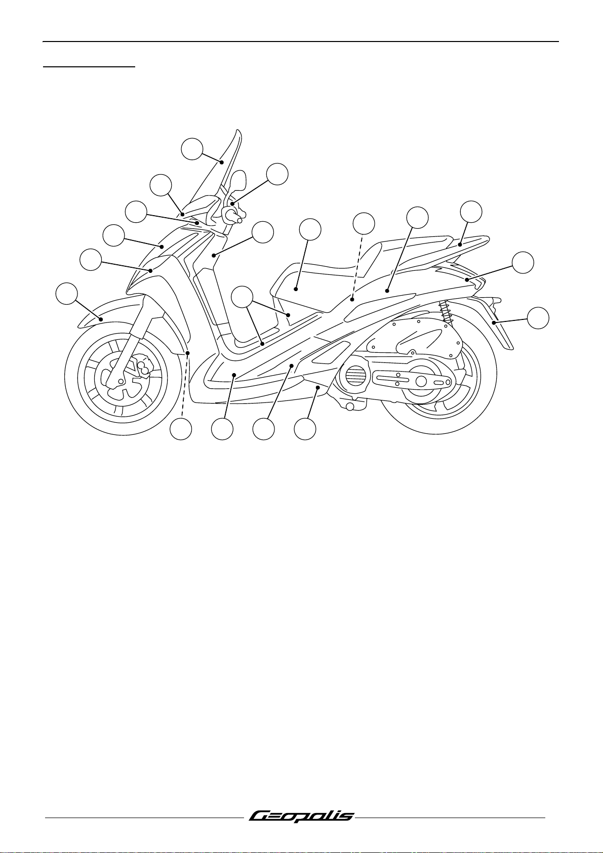
Location of body components
2
1
BODY PANELS
3
4
5
6
19
1. Handlebar front fairing.
2. Wind protector.
3. Counter panel.
4. Lower handlebar cover.
5. Front top cover panel.
6. Front shield panels.
7. Mudguard.
8. Bottom panel.
9. Saddle.
10.Tank streamlining.
10
11
13 8127
9
15
11.Rear shield.
12.Footboard.
13.Access door.
14.Luggage carrier.
15.Helmet compartment.
16.Mudflap.
17.Rear cover.
18.Side panels.
19.Front mudguard.
18
14
17
16
Reproduction or translation, even partial, is forbidden without the written consent of Peugeot Motocycles
19
Page 22

BODY PANELS
Body component sequence of disassembly
1* 5* 8* 9*
26 10
37 1112
4
19*
15*
14
16*
13*
17
*This item may be removed on its own.
20
Reproduction or translation, even partial, is forbidden without the written consent of Peugeot Motocycles
18
Page 23

Removal of the storage compartment
Procedure 1.
- Remove the storage
compartment.(2 screws and 2 nuts).
Removal of a RH or LH side cover
Procedure 2.
- Remove the storage compartment. See:
Procedure 1. page 21.
- Remove the luggage carrier trim.(1)
- Remove the luggage carrier. (2 screws and
1 nuts).
BODY PANELS
1
- Remove the splash guard. (4 screw).
- Disconnect the license plate light.
Reproduction or translation, even partial, is forbidden without the written consent of Peugeot Motocycles
21
Page 24

BODY PANELS
- Remove the rear body cover. (4 screw).
- Remove the access door. (1 screw).
- Remove the 2 screws that secure the
footrest.(2)
- Remove the rear cover 3 fixing screws.(3)
- Unclip the support (A) and remove the side
panel together with the footrest.
3
A
2
Removal of the tank covers
Procedure 3.
- Remove the saddle. (2 screw).
- Remove the battery cover.(1)
- Open the tank filler cap door.
- Remove the upper fairing.(2)
3
1
2
22
Reproduction or translation, even partial, is forbidden without the written consent of Peugeot Motocycles
Page 25

- Remove the 2 fixing bolts.(3)
- Remove the fuel tank cover panel by sliding
it rearwards.
Removal of a RH or LH footboard
Procedure 4.
- Remove the tank cover panel. See:
Procedure 3. page 22.
BODY PANELS
3
2
3
- On each side remove:
• 2 washer head screws. Ø6 mm.(1)
• 1 washer head screws. Ø5 mm.(2)
• 5 plastic screws.(3)
- Remove the access door.
- Separate the front of the footboard which is
linked to the rear part of the leg shield panel.
- Remove the footboard.
3
1
3
Reproduction or translation, even partial, is forbidden without the written consent of Peugeot Motocycles
23
Page 26

BODY PANELS
Removal of the front shield panel
Procedure 5.
- Remove the front top cover panel. (5 screw).
- Remove the footboard mat.
- On each side remove:
• 2 washer head screws. Ø6 mm.(1)
• 2 plastic screws.(2)
- Lift the footboard in order to reach the screw
that secures the shield panel.
1
2
24
Reproduction or translation, even partial, is forbidden without the written consent of Peugeot Motocycles
Page 27
- On each side remove:
• 5 plastic screws.(3)
BODY PANELS
- Remove the centre screw.(4)
- Remove the front legshield assembly.
- Disconnect the lighting and direction
indicator connections.
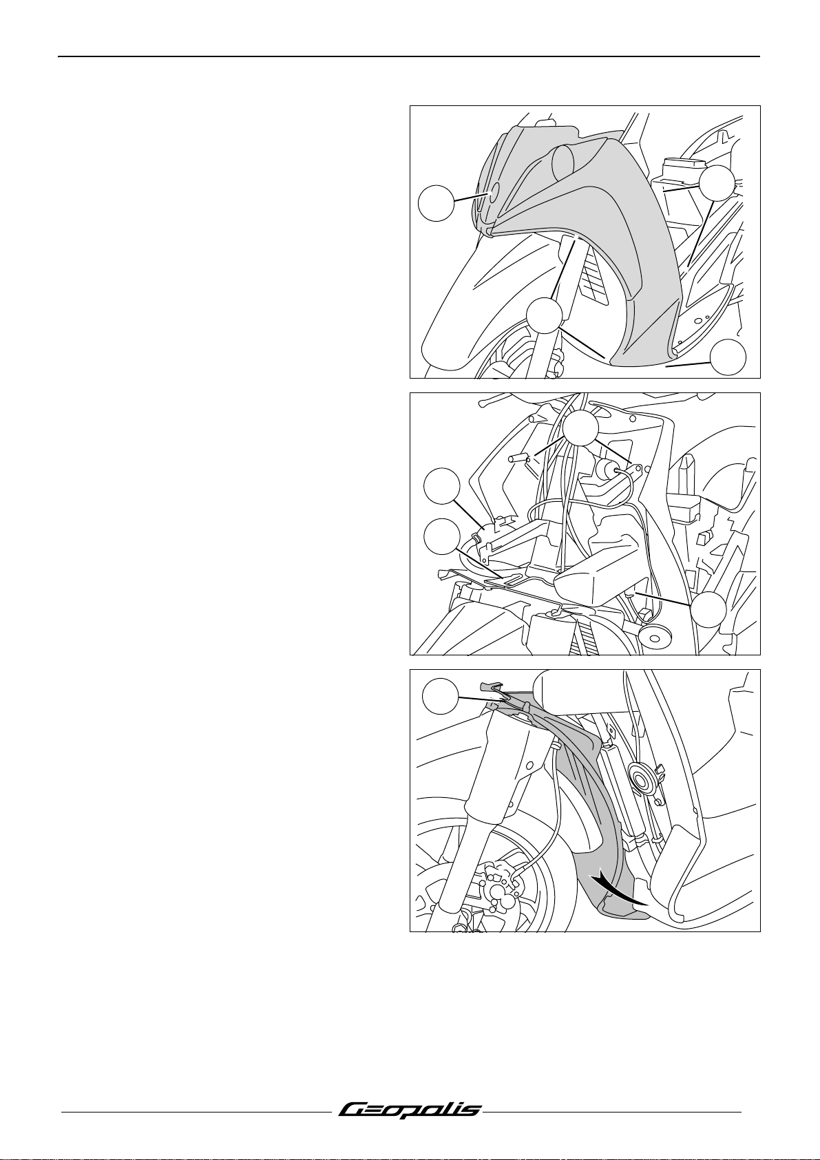
Removal of the rear shield panel
- Remove the footboards. See: Procedure 4.
page 23.
- Remove the front legshield assembly. See:
Procedure 5. page 24.
- Remove the header tank. (Right-hand
side (1))
- Remove the fuse holder. (Right-hand
side (2))
- Disconnect the accessory plug. Left side (3)
- Remove the 2 fixing bolts.(4)
- Remove the rear shield panel.
3
4
3
3
4
1
2
3
Removal of the dirt shield
- Remove the front legshield assembly. See:
Procedure 5. page 24.
- Remove the dirt shield (1) by unclipping it
from the upper bracket and by swivelling it to
the right or to the left.
Note: When removing the dirt cover make
sure it doesn't rub against the
radiator
1
Reproduction or translation, even partial, is forbidden without the written consent of Peugeot Motocycles
25
Page 28

BODY PANELS
Removal of the instrument cluster
- Remove the handlebar front cover.
(2 screw).
- Remove the screen. (4 screw).
- Remove the handlebar rear cover and
instrument cluster assembly. (7 screw).
- Disconnect the instrument cluster.
Removal of the battery holder
Procedure 6.
- Remove the storage compartment. See:
Procedure 1. page 21
- Remove the tank cover panel. See:
Procedure 3. page 22.
- Disconnect and remove the battery.
- Unclip from the battery holder:
• The fuses.(1)
• The relays.(2)
- Remove the battery bracket. (3 screw).
1
2
26
Reproduction or translation, even partial, is forbidden without the written consent of Peugeot Motocycles
Page 29

SERVICE OPERATIONS
Changing the engine oil and replacing
the oil filter
- Remove the engine's oil filler cap.(1)
- Remove the cap and the filter to drain oil
from the engine.(2) (check the condition of
the O-ring and change it if necessary).
SERVICE OPERATIONS
1
- Using a facom D155 type oil filter notched
cap wrench, remove the oil filter.
2
Drain the engine when it is warm.
Wear gloves in order not to get burnt.
Reproduction or translation, even partial, is forbidden without the written consent of Peugeot Motocycles
27
Page 30

SERVICE OPERATIONS
- Lubricate the rubber seal of a new oil filter.
- Using a facom D155 type oil filter notched
cap wrench, install the oil filter.
Tightening torque: 1.4 m.daN.
- Fit the drain plug.
Tightening torque: 2.5 m.daN.
- Fill the engine with 1.7 L motor oil through
the filler hole.
- Fit the filler cap.
- Start the engine, let it run for a few minutes
and then stop it.
- Remove the filler cap and wipe up the oil.
- Fit and screw the cap home.
- Remove the engine's oil filler cap.
- Check the oil level by using the marks on the
filler cap.
A. Oil level high.
B. Oil level low.
A
- Add oil if necessaire.
Note: Check the level with the machine par-
ked on its centre stand, on level
ground.
B
28
Reproduction or translation, even partial, is forbidden without the written consent of Peugeot Motocycles
Page 31

Draining the relay box
500 4T 4V
- Remove the relay box filler cap.(1)
- Remove the screw (2) in order to drain the
relay box.
Note: Replace the copper seal every time
you change oil
SERVICE OPERATIONS
1
- Fit the drain plug.
Tightening torque: 1.5 m.daN.
- Fill the relay box with 0.25 L oil through the
filler hole.
- Fit and screw the cap home.
- Remove the relay box filler cap.
- Check the oil level by using the marks on the
filler cap.
A. Oil level high.
B. Oil level low.
- Add oil if necessaire.
Note: Check the level with the machine par-
ked on its centre stand, on level
ground.
2
A
B
29
Reproduction or translation, even partial, is forbidden without the written consent of Peugeot Motocycles
Page 32

SERVICE OPERATIONS
Replacing the air filter
- Remove the air filter cover (9 bolts) and its
seal.
- Remove the air filter.(1)
1
30
Reproduction or translation, even partial, is forbidden without the written consent of Peugeot Motocycles
Page 33

- Clean or change the filter according to the
maintenance recommendations.
- Clean the air filter with a cleaning and
degreasing agent for air filters.
Note: Do not use a flammable product to
clean the air filter.
- Lubricate the air filter with a special oil for air
filters and squeeze out the excess oil.
- Remove the inlet silencer drain plug to let
humidity and oil drip out.(2)
SERVICE OPERATIONS
2
Reproduction or translation, even partial, is forbidden without the written consent of Peugeot Motocycles
31
Page 34

SERVICE OPERATIONS
Removal of the transmission air filter
Changing the drive pulley bearings
- Remove the 2 air filter box fixing bolts (1).
- Remove the transmission cover
trim.(2) (4 screw)
- Remove the transmission cover
hood.(1) (3 screw)
- Remove the transmission air filter.(2)
- Blow the air filter with compressed air.
1
2
1
- Remove the transmission cover. Refer to
the 400/500cc Engine workshop manual.
4 valves. Reference 759533.
2
32
Reproduction or translation, even partial, is forbidden without the written consent of Peugeot Motocycles
Page 35

Removal of the spark plug
- Remove the access door. (Left side)
- Disconnect the suppressor.
- Remove the spark plug.
Essential precautions: When re-installing,
srew in the spark plug (a few turns)
by hand. For torquing, use a spark
plug wrench equipped with a dial.
- Tighten the spark plug.
Tightening torque: 1.2 m.daN.
Draining the cooling circuit
SERVICE OPERATIONS
- Remove the storage compartment. See:
Procedure 1. page 21.
- Remove the header tank cap.
- Disconnect the lower pump from the coolant
pump to drain the cooling system.(1)
Note: The cooling system is drained when
the engine is cold.
- Connect the lower hose to the water pump.
- Fill the circuit with 1.4 L of coolant.
- Loosen the bleeder screw (2) to remove air
contained in the engine.
- Close the bleeder screw.
Tightening torque: 0.3 m.daN.
- Start the engine and accelerate in order to
warm it up.
- Stop the engine once it reaches its operating
temperature. (Approximately 90°C)
1
2
Reproduction or translation, even partial, is forbidden without the written consent of Peugeot Motocycles
33
Page 36

SERVICE OPERATIONS
- Check the coolant level in the header tank.
- If necessary add coolant in the header tank.
A. Maximum level.
B. Minimum level.
Note: Check the level with the machine par-
ked on its centre stand, on level
ground.
Installing the valve clearance.
- Remove the storage compartment. See:
Procedure 1. page 21.
- Remove the battery bracket. See:
Procedure 6. page 26.
- Remove the access doors.
- Remove the rocker cover. (6 screw).
A
B
Tightening torque: 0.8 m.daN.
- Remove the 2 air filter box fixing bolts (1).
- Remove the transmission cover trim.(2)
(4 screw)
1
2
34
Reproduction or translation, even partial, is forbidden without the written consent of Peugeot Motocycles
Page 37

- Rotate the engine by hand in the operating
direction in order to align the (A) mark on the
pinion with the mark on the cylinder head.(B)
SERVICE OPERATIONS
- Loosen the lock nut of the rocker
adjustment screw.(3)
- By means of feeler gauges, adjust the
clearance of every valve by acting on the
rocker set screw.
Clearances:
• 15/100 at the intake.
• 15/100 at the exhaust.
B
A
3
- Immobilize the rocker set screw.
- Tighten the locknut without altering the
adjustment.
- Check the adjustment.
Reproduction or translation, even partial, is forbidden without the written consent of Peugeot Motocycles
35
Page 38

SERVICE OPERATIONS
Replacing the brake pads
Front brake
- Remove the 2 spindles (1).
- Remove the calliper. (2 screw).
Tightening torque: 2.5 m.daN.
- Remove the brake pads.
Mini. thickness: 1.5 mm.
- When refitting the brake pads, push the
pistons all the way into their housing.
Note: After refitting, actuate the brake
levers several times to bring the
brake pads against the brake disc.
Rear brake
- Remove the exhaust muffler trim. (3 screw)
1
- Remove the heat shield. (3 screw)
36
Reproduction or translation, even partial, is forbidden without the written consent of Peugeot Motocycles
Page 39

- Loosen the collars.(1)
- Remove the upper fixing bolts.(2)
- Remove the exhaust.
Tightening torque: 1 m.daN.
- Remove the collar retaining pin.(3)
- Remove the collar.
SERVICE OPERATIONS
2
1
- Remove the 2 lower fixing bolts (4) from the
mudflap.
3
4
Reproduction or translation, even partial, is forbidden without the written consent of Peugeot Motocycles
37
Page 40

SERVICE OPERATIONS
- Remove the 2 screws that secure the stand
support.(5)
Tightening torque: 2.2 m.daN.
- Remove the 2 nuts that secure the arm.(6)
Tightening torque: 2.8 m.daN.
- Remove the shock absorber lower
mount (7).
Tightening torque: 4.5 m.daN.
- Remove the pin, the nut retainer and the
wheel nut.(8)
Tightening torque: 13.5 m.daN.
- Remove the suspension arm.
6
5
7
8
- Remove the spacer.(9)
- Remove the wheel. (5 screw)
Tightening torque: 2.5 m.daN.
9
38
Reproduction or translation, even partial, is forbidden without the written consent of Peugeot Motocycles
Page 41

- Remove the calliper. (2 screw).
Tightening torque: 2.5 m.daN.
- Remove the 2 spindles (10).
- Remove the brake pads.
Mini. thickness: 1.5 mm.
SERVICE OPERATIONS
10
- When refitting the brake pads, push the
pistons all the way into their housing.
Note: After refitting, actuate the brake
levers several times to bring the
brake pads against the brake disc.
Reproduction or translation, even partial, is forbidden without the written consent of Peugeot Motocycles
39
Page 42

SERVICE OPERATIONS
Checking the brake fluid level
- Position the handlebars so that the master
cylinder will be horizontal.
- Check the brake fluid level and if necessary
top up in the master cylinder.
A. Maximum brake fluid level.
B. Minimum brake fluid level.
- Remove the screen.
- Remove the handlebar rear cover and
instrument cluster assembly. (7 screw)
- Remove the cover and the diaphragm from
the master cylinder. (2 screw)
- Add brake fluid until it reaches the maximum
level.(A)
A
LOW
B
2
2
40
Reproduction or translation, even partial, is forbidden without the written consent of Peugeot Motocycles
Page 43

SERVICING THE ABS/MBS SYSTEM
SERVICING THE ABS/MBS SYSTEM
Reminder
The ABS/PBS system features 3 distinctive functions:
1. Combined front and rear braking system controlled by the LH brake lever.
2. Braking assistance system provided on the front wheel.
3. Anti-locking system provided on the front wheel.
Before servicing the system, carry out a diagnosis using the diagnostic tool and print out a parameter
report.
If fault codes appear, repair as required.
The diagnostic light of the system only goes off when the machine reaches 5 km/h.
The rider brakes with the left lever (integral braking), and the right lever (braking on the front wheel
only) becomes an emergency brake.
For diagnosing the ABS/MBS system, see document: ABS/MBS braking system functioning
principle. Reference: 759568.
Removal of the brake modulator
- Remove the front legshield assembly. See:
Procedure 5. page 24.
- Remove the screen.
- Remove the handlebar rear cover and
instrument cluster assembly. (7 screw)
- Remove the mudguard.
Plastic parts must be protected from brake fluid splashes.
Hold the brake levers at 20 mm from the rest position using plastic straps. This
operation allows you to close the circuits and to avoid emptying the
hydraulic controls when disconnecting the modulator.
20 mm
Do not remove the master cylinder covers.
Reproduction or translation, even partial, is forbidden without the written consent of Peugeot Motocycles
41
Page 44

SERVICING THE ABS/MBS SYSTEM
- Disconnect the modulator.
- Disconnect the hydraulic controls.
- Remove the brake modulator. (2 nuts)
Place a pan under the modulator so that the
brake fluid will drip into it.
The modulator shall not be open, the manufacturer is the only one allowed to service this
component.
Re-installing the modulator
- Place the modulator in its support.
Tightening torque: 2.2 m.daN.
- Position the hydraulic controls in the
indicated order:
• The hydraulic control coming from the LH
master cylinder.(1)
• The hydraulic control going to the rear brake
calliper.(2). Place it over the hydraulic
control.(1)
• The hydraulic control coming from the RH
master cylinder.(3)
• The hydraulic control going to the front
brake calliper.(4)
Tightening torque: 2.8 m.daN.
3
2
1
4
Change the copper seals each time they
are removed.
- Connect the modulator.
- Bleed the hydraulic system according to the
required procedure.
42
Reproduction or translation, even partial, is forbidden without the written consent of Peugeot Motocycles
Page 45

SERVICING THE ABS/MBS SYSTEM
Bleed procedure
Reminder:
- The rear brake hydraulic system is drained using the LH lever.
- The front brake hydraulic system is drained using the RH lever.
- The front and rear brake systems are drained the usual way.
- The brake assistance circuit is drained by actuating the modulator pump by means of the
diagnostic tool.
Note:
- Plastic parts must be protected from brake fluid splashes.
- Remove the hook or plastic strap in order to free the control lever.
Equipment required:
• 500 ml brake fluid of minimum grade: DOT4.
• Bleed syringe. P/N: 754306.
• Transparent pipe.
• 2 additional 100 ml reservoirs.
Draining the rear brake circuit
- Remove the cover from the LH master
cylinder.
- Using the syringe, empty the LH master
cylinder.
- Position the handlebars so that the master
cylinder is in its uppermost position, in order
to expell the air bubbles from the circuit.
- Fill the syringe with brake fluid.
- Connect the syringe to the bleed screw of
the rear calliper.
- Open the bleed screw by 1 to 2 turns.
- Inject the brake fluid slowly into the circuit
until the level inside the reservoir of the
master cylinder is halfway up.
- Close the caliper bleed screw.
Reproduction or translation, even partial, is forbidden without the written consent of Peugeot Motocycles
43
Page 46

SERVICING THE ABS/MBS SYSTEM
- Slowly actuate the brake control lever by
displacing it 2 cm (A) maximum from its rest
position until no more bubbles can be seen
coming up through the master cylinder.
- This operation can take a few minutes.
- Connect a reservoir containing brake fluid to
the rear brake calliper bleed screw using a
transparent pipe.. The reservoir must be
kept higher than the brake calliper to easily
check that the air bubbles are being
expelled.
- Open the bleed screw by 1 to 2 turns.
A
- Actuate the LH brake lever in an even way
and without undue haste while topping up
with brake fluid in the master cylinder.
Note: Don't lean over the master cylinder
when bleeding the circuit in order
not to get splashed by brake fluid.
- Stop the operation when no more bubbles
are expelled from the calliper bleeder screw.
- Close the caliper bleed screw.
- Check the firmness of the lever without
roughly squeezing the lever to avoid the
brake fluid from splashing out.
- Otherwise, repeat the operation from the
beginning.
- Check the brake fluid level and if necessary
top up in the master cylinder, and re-fit the
master cylinder cover.
44
Reproduction or translation, even partial, is forbidden without the written consent of Peugeot Motocycles
Page 47

Bleeding the assistance circuit
Note: Before servicing the assistance
system you must absolutely be sure
that the battery is perfectly charged,
as a considerable voltage drop
would immediately turn off the
assistance pump.
- Connect the additional reservoir equipped
with a transparent pipe to the modulator's
reservoir screw plug (1) and fill.
- Open the screw plug by 2 or 3 turns.
- Connect the reservoir containing brake fluid
to the front brake calliper bleed screw using
a transparent pipe. The reservoir must be
kept higher than the brake calliper to easily
check that the air bubbles are being
expelled.
- Open the bleed screw by 1 to 2 turns.
- Turn on the ignition.
- Connect the diagnostic tool and actuate the
modulator pump.
- Regularly add brake fluid in the additional
reservoir.
- Stop the operation when there are no more
bubbles in the transparent pipe.
- Close the caliper bleed screw.
SERVICING THE ABS/MBS SYSTEM
1
As a precautionary measure, the pump
shall not continuously operate for
more than 2 minutes.
Reproduction or translation, even partial, is forbidden without the written consent of Peugeot Motocycles
45
Page 48

SERVICING THE ABS/MBS SYSTEM
Draining the front brake circuit
- Remove the cover from the RH master
cylinder.
- Using the syringe, empty the RH master
cylinder.
- Position the handlebars so that the master
cylinder is in its uppermost position, in order
to expell the air bubbles from the circuit.
- Fill the syringe equippd with a transparent
pipe with brake fluid.
- Connect the syringe to the bleed screw of
the front calliper.
- Open the bleed screw by 1 to 2 turns.
- Inject the brake fluid slowly into the circuit
until the level inside the reservoir is halfway
up.
- Close the caliper bleed screw.
- Slowly actuate the brake control lever by
displacing it 2 cm (A) maximum from its rest
position until no more bubbles can be seen
coming up through the master cylinder.
- This operation can take a few minutes.
A
46
Reproduction or translation, even partial, is forbidden without the written consent of Peugeot Motocycles
Page 49

- Connect the reservoir containing brake fluid
to the modulator bleed screw (1) using a
transparent pipe. The reservoir must be kept
higher than the modulator to easily check
that the air bubbles are being expelled.
- Open the bleed screw by 1 to 2 turns.
- Actuate the RH brake lever in an even way
and without undue haste while topping up
with brake fluid in the master cylinder.
SERVICING THE ABS/MBS SYSTEM
1
Note: Don't lean over the master cylinder
when bleeding the circuit in order
not to get splashed by brake fluid.
- Stop the operation when no more bubbles
are expelled from the modulator.
- Close the bleeder screw.
Reproduction or translation, even partial, is forbidden without the written consent of Peugeot Motocycles
47
Page 50

SERVICING THE ABS/MBS SYSTEM
- Connect the reservoir containing brake fluid
to the front brake calliper bleed screw using
a transparent pipe. The reservoir must be
kept higher than the brake calliper to easily
check that the air bubbles are being
expelled.
- Open the bleed screw by 1 to 2 turns.
- Actuate the RH brake lever in an even way
and without undue haste while topping up
with brake fluid in the master cylinder.
- Stop the operation when no more bubbles
are expelled from the calliper bleeder screw.
- Close the caliper bleed screw.
- Check the firmness of the lever.
- Otherwise, repeat the operation from the
beginning.
- Check the brake fluid level and if necessary
top up in the master cylinder, and re-fit the
master cylinder cover.
Integral braking system static test.
- Wedge the machine frame so that the front wheel is not in contact with the floor.
- Turn on the ignition.
- Turn the front wheel at over 5 km/h, and operate one of the brake levers to check that
the high pressure pump operates with both levers.
- Check by actuating the LH control lever: the front wheel stops.
- If not, repeat the operation: Bleeding the assistance circuit.
48
Reproduction or translation, even partial, is forbidden without the written consent of Peugeot Motocycles
Page 51

MISCELLANEOUS OPERATIONS
Procedure for reducing the fuel circuit
pressure
Procedure 7.
- Remove the storage compartment. See:
Procedure 1. page 21.
- Disconnect the fuel injector.
- Remove the fuel injector without
disconnecting the supply hose.
- Connect the fuel injector power supply
harness tool P/N 756017 to the fuel injector
and the battery.
- Place the injector above a pan.
- Actuate the contact switch of the tool 3 times
for 5 seconds while respecting a released
time of 5 seconds between each action, in
order to drop the pressure inside the supply
hose of the fuel manifold.
756017
UPPER LEVEL
LOWER LEVEL
MISCELLANEOUS OPERATIONS
The pressurised jet of fuel may be dangerous for the skin, do not expose the hands to the jet of
fuel when opening the injector.
Reproduction or translation, even partial, is forbidden without the written consent of Peugeot Motocycles
49
Page 52

MISCELLANEOUS OPERATIONS
Checking fuel pressure
- Remove the tank cover panel. See:
Procedure 3. page 22.
- Carry out the procedure for lowering the
pressure in the fuel system. See:
Procedure 7. page 49.
- Disconnect the fuel supply hose. (1 "click"
collar).
- Insert the pressure gauge P/N 757877
between the gauge well and the supply
hose.
- Always use hose clamps that are in good
condition.
- Turn the ignition on 3 times to bleed the fuel
system.
- With the engine stopped, check the fuel
pressure which must be 2.5 bars when
switching on the fuel pump.
Before disconnecting the pressure gauges, lower the fuel pressure in the fuel system.
Always reinstall the hoses with new hose clamps.
4
2
6
0
8
bar
10
50
Reproduction or translation, even partial, is forbidden without the written consent of Peugeot Motocycles
Page 53

Removal of the fuel pump
- Remove the tank cover panel. See:
Procedure 3. page 22.
- Carry out the procedure for lowering the
pressure in the fuel system. See:
Procedure 7. page 49.
- Disconnect the fuel pump.(1)
- Disconnect the fuel pipe by pressing against
the ring (A) to remove the quick disconnect
coupler (2).
- Loosen by hand the pump locking ring.(3)
- Remove the fuel pump.
3
MISCELLANEOUS OPERATIONS
1
2
A
Reproduction or translation, even partial, is forbidden without the written consent of Peugeot Motocycles
51
Page 54

MISCELLANEOUS OPERATIONS
Removal of the fuel gauge
- Remove the tank cover panel. See:
Procedure 3. page 22.
- Disconnect the fuel gauge.
Using tool P/N 756715, remove the fuel gauge.
Note: Modify the tool P/N 756715 as shown
in the sketch in order to use it with
the Geopolis.
756715
52
Reproduction or translation, even partial, is forbidden without the written consent of Peugeot Motocycles
Page 55
Removal of the throttle box
MISCELLANEOUS OPERATIONS
- Remove the storage compartment. See:
Procedure 1. page 21
- Disconnect the battery.
- Remove the intake silencer. (2 clips and
3screws).
- Remove the screw that secures the wiring
harness clamp and the fuel hose anchor
bracket.(A)
- Disconnect the throttle unit.(1)
- Remove the 3 screws that secure the
throttle box.(2)
- Remove the throttle box.
- Disconnect the throttle control cables.(3)
3
2
A
1
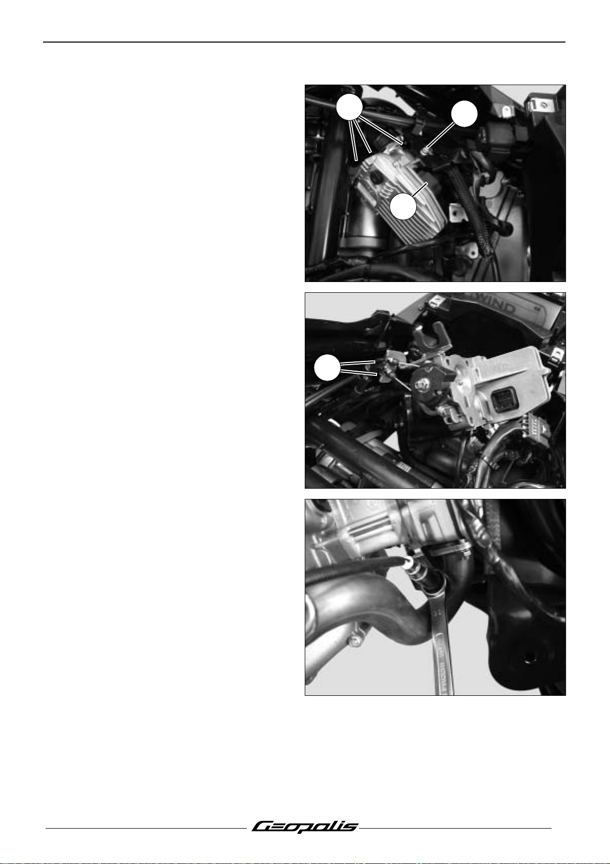
Removal of the lambda sensor
- Remove the storage compartment. See:
Procedure 1. page 21.
- Remove the RH fairing. See: Procedure 2.
page 21.
- Disconnect the lambda sensor.
- Using a box-end wrench, remove the
lambda sensor.
Tightening torque: 4.5 m.daN.
Reproduction or translation, even partial, is forbidden without the written consent of Peugeot Motocycles
53
Page 56

MISCELLANEOUS OPERATIONS
Note: When reinstalling, lubricate the
threads (A) of the sensor with graphite grease.
In order not to damage the Lambda sensor, never lubricate or clean the end piece (B) which is
exposed to the exhaust gas.
A
B
- When re-installing, make absolutely sure
there is the fuel tank heat shield (1) and its
pin.(2)
Removal of the regulator
- Remove the storage compartment. See:
Procedure 1. page 21.
- Remove the RH fairing. See: Procedure 2.
page 21.
- Disconnect and remove the regulator.(1)
2
1
1
54
1
Reproduction or translation, even partial, is forbidden without the written consent of Peugeot Motocycles
Page 57

Removal of the radiator
MISCELLANEOUS OPERATIONS
- Remove the tank cover panel. See:
Procedure 3. page 22.
- Disconnect the fan.(1)
- Remove the front shield panel. See:
Procedure 5. page 24.
- Remove the mudguard.
- Remove the upper fixing bolts.(2)
- Drain the cooling circuit.
- Disconnect the 4 hoses of the radiator's
cooling circuit.
- Remove the radiator.
1
2
- Remove the fan.(3).(3 screw)
3
Reproduction or translation, even partial, is forbidden without the written consent of Peugeot Motocycles
55
Page 58

MISCELLANEOUS OPERATIONS
Removal of the engine mounting
assembly
- Remove the side fairings. See:
Procedure 2. page 21.
- Suspend the rear of the machine.
- Remove the intake silencer. (1) (2 clips and
3screws).
- Remove the sheath holder.(A)
- Loosen the linkrod connecting pin nut.(1)
- Loosen the 2 nuts.(2)
A
Tightening torque: 9.5 m.daN.
- Remove the 2 nuts from the torque rods.(3)
Tightening torque: 3.6 m.daN.
1
2
3
3
56
Reproduction or translation, even partial, is forbidden without the written consent of Peugeot Motocycles
Page 59

- Remove the linkrod-to-engine connecting
pin.(1)
- Remove the linkrod-to-frame connecting
pin.(2)
MISCELLANEOUS OPERATIONS
2
- Remove the linkrod connecting pin.(3)
- Check the condition of the spacers and
needle bearings.(7)
- Make sure that the silent block is not
cracked.(8)
1
3
Note: We recommend greasing all needle
bearings when refitting these parts.
- When re-installing, fit the rubber bushings
with the colours shown:
A. Blue
B. Black
C. Grey
Reproduction or translation, even partial, is forbidden without the written consent of Peugeot Motocycles
7
8
A
B
2
C
B
8
57
Page 60

MISCELLANEOUS OPERATIONS
Removal of the engine
Note: To remove the cylinder head, remove
the power propulsion unit.
For removal of the cylinder head, cylinder
and piston, see the workshop
manual: 4 stroke engine. 4 valves.
Reference: 758851
- Disconnect the battery.
- Remove the side fairings. See:
Procedure 2. page 21.
- Disconnect the lambda sensor.(1)
- Remove the exhaust assembly.
- Remove the intake silencer.(2)
- Remove the rear mudguard.(3)
1
3
- Remove the screw that secures the wiring
harness clamp and the fuel hose anchor
bracket.(A)
- Disconnect:
• The fuel injector.(4)
• The throttle box.(5)
• The temperature sensor.(6)
• The magneto.(7)
• The suppressor.
- Disconnect the injector fuel feed hose.(8)
4
2
6
8
7
A
5
58
Reproduction or translation, even partial, is forbidden without the written consent of Peugeot Motocycles
Page 61

- Disconnect:
- Oil pressure switch.(9)
- Disconnect:
• The engine ground.(10)
• The starter motor.(11)
MISCELLANEOUS OPERATIONS
9
10
- Disconnect the lower pump from the coolant
pump to drain the cooling system.
- Disconnect the cylinder head hose.(12)
11
12
Reproduction or translation, even partial, is forbidden without the written consent of Peugeot Motocycles
59
Page 62

MISCELLANEOUS OPERATIONS
- Remove the suspension arm.
- Remove the wheel.
- Remove the calliper.(13)
- Re-install the wheel.
- Suspend the rear of the machine.
- Remove the shock absorber lower
mount (14).
13
- Remove the linkrod-to-engine connecting
pin.(15)
14
15
60
Reproduction or translation, even partial, is forbidden without the written consent of Peugeot Motocycles
Page 63

- Lift the rear of the machine.
- Disconnect the throttle control cables.(16)
- Remove the engine.
- Remove the 4 spacers.(17)
MISCELLANEOUS OPERATIONS
16
- When re-installing, make absolutely sure
there is the fuel tank heat shield (1) and its
pin.(2)
17
17
2
1
Reproduction or translation, even partial, is forbidden without the written consent of Peugeot Motocycles
61
Page 64

MISCELLANEOUS OPERATIONS
Removal of the fork
Replacing the bearings of the steering
system
- Remove the front top cover panel.
- Remove the handlebar front and rear
covers.
- Remove the 2 upper screws that secure the
rear shield panel.
- Remove the braking units on the
handlebars.(1)
- Remove the handlebars from the fork tube.
- Remove the front mudguard.
- Remove the front brake caliper from the fork
tube.
- Remove the front wheel.
- Using tool P/N 757860 remove the steering
locknut.
- Remove:
• The lock washer.
• the adjustable cone locknut.
• the rubber washer.
• the adjustable cone.
757860
1
757860
- Remove the fork.
- Remove the balls.
- Using a drift, remove the steering head
cups.
62
Reproduction or translation, even partial, is forbidden without the written consent of Peugeot Motocycles
Page 65

- Using a chisel, pry the steering head cup off
by pressing the tool behind the dust cover.
- Install the following new parts:
• The plain washer.(1)
• The dust cover.(2)
• The fork cone.(3)
MISCELLANEOUS OPERATIONS
3
- Install new steering head cups using tool
P/N 758810.
758810
1
2
Reproduction or translation, even partial, is forbidden without the written consent of Peugeot Motocycles
63
Page 66

MISCELLANEOUS OPERATIONS
Steering system tightening method
- Grease the cup bearing races.
- Fit the caged ball bearings. (1 and 2).
- Fit the fork into the steering column.
- Install the adjustable cone and tighten it.(3)
Tightening torque: 4 m.daN.
- Loosen and then retighten the adjustable
cone.
Tightening torque: 2.2 m.daN.
- Install the rubber washer.(4)
- Finger tighten the adjustable cone
locknut (5) so that its notches are aligned
with those of the adjustable cone.
- Fit the lock washer (6) in the notches of the
locknut and adjustable cone.
- Install the steering head locknut and tighten
it.(7)
Tightening torque: 7.5 m.daN.
7
5
6
2
3
4
1
64
Reproduction or translation, even partial, is forbidden without the written consent of Peugeot Motocycles
Page 67

Page 68

P/N. 759538
In our permanent concern to make improvements PEUGEOT MOTOCYCLES reserves the right to suppress,
modify, or add any reference mentioned.
DC/PS/APV Printed in the E.U. 07/2007 (non contractual pictures)
 Loading...