


PRINCIPLE OF OPERA TION
PERFORMANCE
MH™-Series Humidifiers are shell and tube
moisture exchangers that allow the transfer of
water vapor between a liquid water supply and a
flowing gas stream. Water is absorbed into the
walls of the Nafion® tube and transferred to the
dry gas stream. This transfer is driven by the
difference in partial pressures of water vapor on
the opposing sides.
MH HUMIDIFIER SPECIFICA TIONS
A
Model Number A B C
MH-(070 or 110)-12 14+/ -1 /4" 10" 1/4"
MH-(070 or 110)-24 26+/ -1/4" 22" 1/4"
MH-(070 or 110)-48 50+/ -1/4" 46" 1/4"
Sampl e F i ttings 1/8" or 1/4" , Purge Fi t ting 1/ 4" Compression.
MH-070 humidifier’s performance is shown in
the chart below. The MH-110 which has a
slightly larger ID shows about a 3 degree higher
outlet dew point. MH-110 should be chosen
when a lower pressure drop is desired.
MH-070 Humidi fi er Performa n ce
70
60
50
40
30
Dew point (C)
20
10
0
12"0.512345678910
24"1 2 4 6 8 101214161820
48" 2 4 8 12 16 20 24 28 32 36 40
Ambient 30 C 50 C 70 C
MH™- Series
Humidifier
User Manual
INSTALLATION SPECIFICA TIONS
Warning!
Do not allow Nafion tube to dry out.
Nafion will shrink up to 125% and pull
out of the end fittings or break. Should
the element dry, soak it in DI water for
5 minutes before re-assembly.
1. Use only de-ionized water.
2. Controlled temperature water.
3. Do not allow unit to dry out. If element dries
completely, soak in DI water for 1 hour.
Flow Rate (l/min.)
MH-070 Performance Chart
Nafion® is a registered trademark of DuPont.
MH™ is a tradmark of Perma Pure LLC.
Bulletin# 206
PERMA PURE
8 Executive Drive
Toms River, N.J. 08755
Phone: 800-337-3762
732-244-0010
Fax: 732-244-8140
e-mail: info@permapure.com
Web Site: www.permapure.com
SIPHON FEED METHOD
ROTATE TEE FITTINGS
In the Siphon feed setup (shown in Figure 1),
temperature at which the air will be fully saturated
(“dew point”) must be determined. The humidifier
must be heated or insulated to this temperature and
kept constant. A reservoir of de-ionized water is
pulled through to fill the shell side and cap off at the
outlet. A positive pressure sample gas is pushed
through the inner tubes and is humidified.
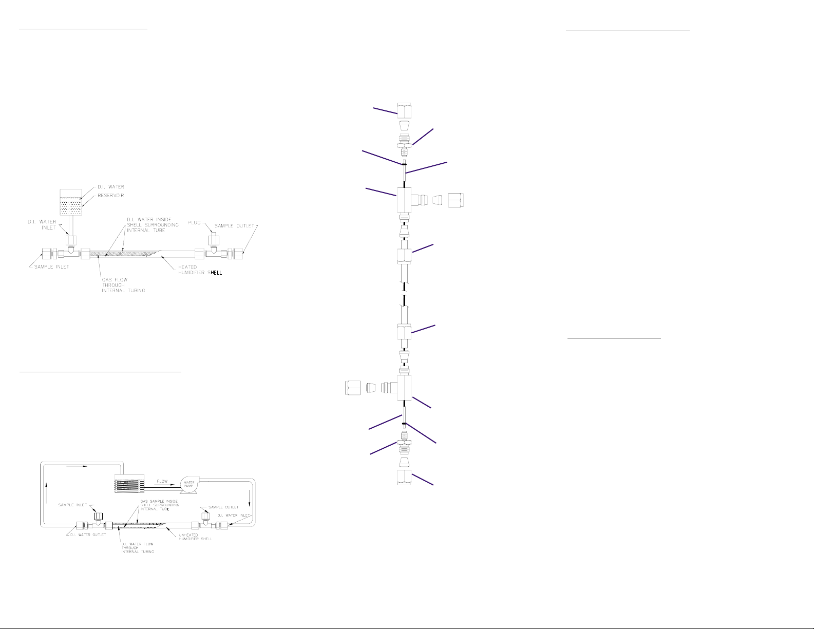
Figure 1
Nut
O-Ring
Tee Fitting
Union Fitting
Element
Inside Nut
Inside Nut
Tools Needed:
- Two wrenches- 5/8 and 7/16
- Tweezers
1. Hold tee fitting with 7/16 wrench and loosen
union connector fitting with 5/8 wrench (refer
to Figure 3).
2. Remove fitting.
3. Rotate dryer element 10 degrees each way
with tweezers or fingertips.
4. With two wrenches, loosen inside nut
connecting tee fitting to shell tube.
5. Rotate tee fitting to desired location and
tighten into place.
6. Install union into tee fitting while making sure
element is not pushed back out of o-ring seal.
Take caution to ensure element does not
rotate inside shell.
7. Tighten union fitting by hand and then tighten
1/4 turn with wrench.
DISASSEMBLING
CIRCULATION FEED METHOD
The circulation method (shown in Figure 2) requires
heated water to be continuously circulated. The flow
with greater pressure needs to be flowing inside the
tubes to prevent tubing collapse.
Figure 2
Element
Union Fitting
Figure 3
Tee Fitting
O-Ring
Nut
Tools Needed:
- Two wrenches - 5/8 and 7/16
- Pair of lightweight gloves
1. Repeat steps 1-4 for other end.
2. Put on lightweight gloves to protect membrane
tubing (skin oils can contaminate surface).
3. Gently push one end of element out of o-ring
while pulling other end out of tee fitting.
4. Gently pull element out of housing from
opposite end.
5. Reverse for reassembly.
6. Element ends should extend equally from
each end of shell housing before installing
union fittings. Soak element for 5 minutes in
DI water if it is too short.
 Loading...