

Page 1
PRINCIPLE OF OPERATION
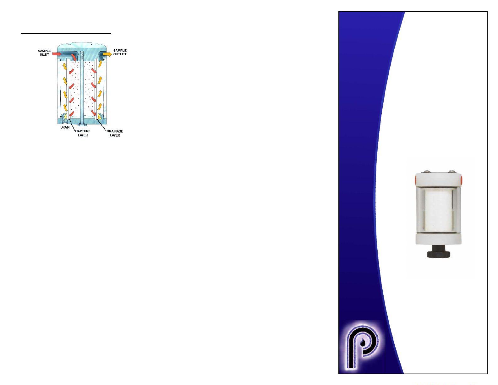
Figure 1 - Illustration
FF-250™ Series Filters may be connected for
particulate only or for coalescing and particulate filtration. It will remove liquid droplets and
particles down to 0.1 micron with an efficiency
of 95% or greater. The thick, high capacity
borosilicate glass and Teflon filter element will
uniformly drains coalesced liquids to bottom
of housing, where they can be evacuated
through the 1/8” NPT drain port.
FF-250™ Series
Filter
User Manual
Coalescing filtration is achieved by forcing
gas stream through the inside of the filter
element. Figure 1 shows the flow path in a
coalescing application. In this mode, small
aerosol particles are forced together as they
pass through the fine inner layer of the filter
element. Larger drops created in this process
begin to fall out of the gas stream due to their
mass. The coarse drain layer on the outside
of the filter element assists this physical
separation.
When used in a particulate-only application,
the filter can be installed so that the gas
stream fills the filter shell first then is forced
through the element. Captured particulate
collects on the visible, outside surface of the
element. This allows visual determination of
the element condition.
FF-250TM is a Tradmark of Perma Pure LLC, Kynar® is a
Registered Trademark of Elf Autochem North America,
Hastelloy is a Registered Trademark of H aynes
International, Teflon® is a Registered Trademark of E.I.
Dupont.
Bulletin 221
PERMA PURE
8 Executive Drive
Toms River, N.J. 08755
Phone: 800-337-3762
732-244-0010
Fax: 732-244-8140
e-mail: [email protected]
Web Site: www.permapure.com
Page 2
FILTER SPECIFICATIONS
REPLACING FILTER ELEMENT
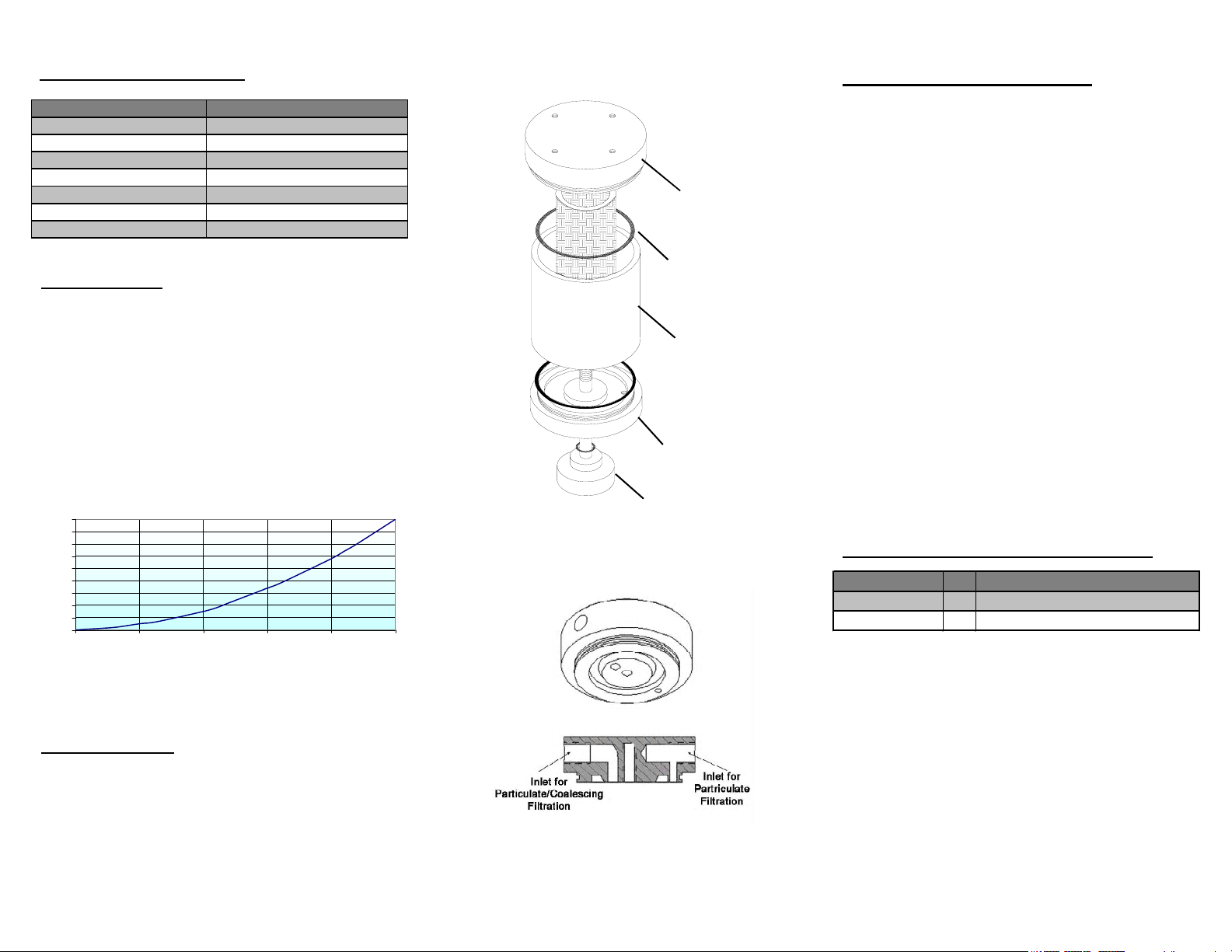
Description Spe cification
Top and Bottom Materials 316 SST or Kynar®
Shell Material Borosilicate Glass or 316 SST
Maximum Temperature Shell: K ynar 120°C, SST 230°C
Maximum Pressure 30 PSIG
Dimensions 2.5" dia. X 4.0" h
Inlet, Outlet and Drain Ports 1/8" NPT Female
Center Bolt 1/4-20 x 3.25", Hastelloy® C276
INSTALLATION
All ports are 1/8” NPT female. To use filter as a
particulate filter, connect sample to port aligned
with hole on underside of top cap. (Refer to
Figure 4)
To use as a coalescer, have sample flow inside
filter element by connecting sample inlet to other
port.
PRESSURE DROP vs. FLOW
90
80
70
60
50
40
30
PRESSURE DROP,
20
10
INCHES OF WATER COLUMN
0
0 5 10 15 20 25
FLOWRATE, LPM OF AIR, 0 PSIG
Top Cap
O-ring
Shell
Bottom Cap
Bolt
Figure 3 - Exploded View
FF-250 filter should be checked regularly to ensure
element is in good condition. If filter element
appears to be dirty or begins to cause flow
restriction in system, it should be replaced.
1. Loosen bolt on bottom of filter housing.
2. Pull assembly apart and remove element.
3. Install glass shell onto bottom piece - a slight
twist may be necessary to get the shell over the
o-ring.
4. Place the new element into grooves in top and
bottom of housing.
5. Assemble top to shell assembly.
6. Make sure the element is seated correctly in top
groove.
7. Replace bolt through bottom piece and screw
into top piece. Tighten just enough so it does not
vibrate loose.
PART NUMBERS FOR REPLACEMENT
Part Number Qty Description
FF-250-E-2.5G 1 Replacement Filter Element
FF-250-3 1 Replacement O-Rings, Set of 3
Figure 2 - Pressure Drop Curv e
PERFORMANCE
FF-250 filters will remove liquid droplets and
particles down to 0.1 micron with an efficiency of
95% or greater.
Figure 4 - Top Cap
 Loading...