

Page 1

PERMA PURE LLC
T
Baldwin™-Series
Model M8B
Tester’s Choice Portable
Sample Conditioning System
User’s Manual
PERMA PURE LLC
8 Executive Drive ▪ P.O. Box 2105 ▪
oms River, NJ 08754
Page 2

Model M8B User’s Manual
Doc. #580: Revision: 000
Page 2 of 22
PERMA PURE LLC
Contents
Introduction ...................................................................................................................... 3
General description ............................................................................................................ 4
Specifications .................................................................................................................... 6
Connections................................................................................................................... 6
Important Safety Warnings ................................................................................................. 7
Connection & Start-up ........................................................................................................ 8
Sample and Drain Connections ......................................................................................... 8
LED Summary.............................................................................................................. 10
Start-up ......................................................................................................................... 11
Set Points ....................................................................................................................... 12
Shutdown ....................................................................................................................... 12
Replacement Parts ........................................................................................................... 15
Appendix A: Installation of Peristaltic Pump ........................................................................ 16
Appendix B: Drawings ..................................................................................................... 17
B1: 4S-M8 flow diagram ............................................................................................... 17
B2: Impinger schematic ............................................................................................... 17
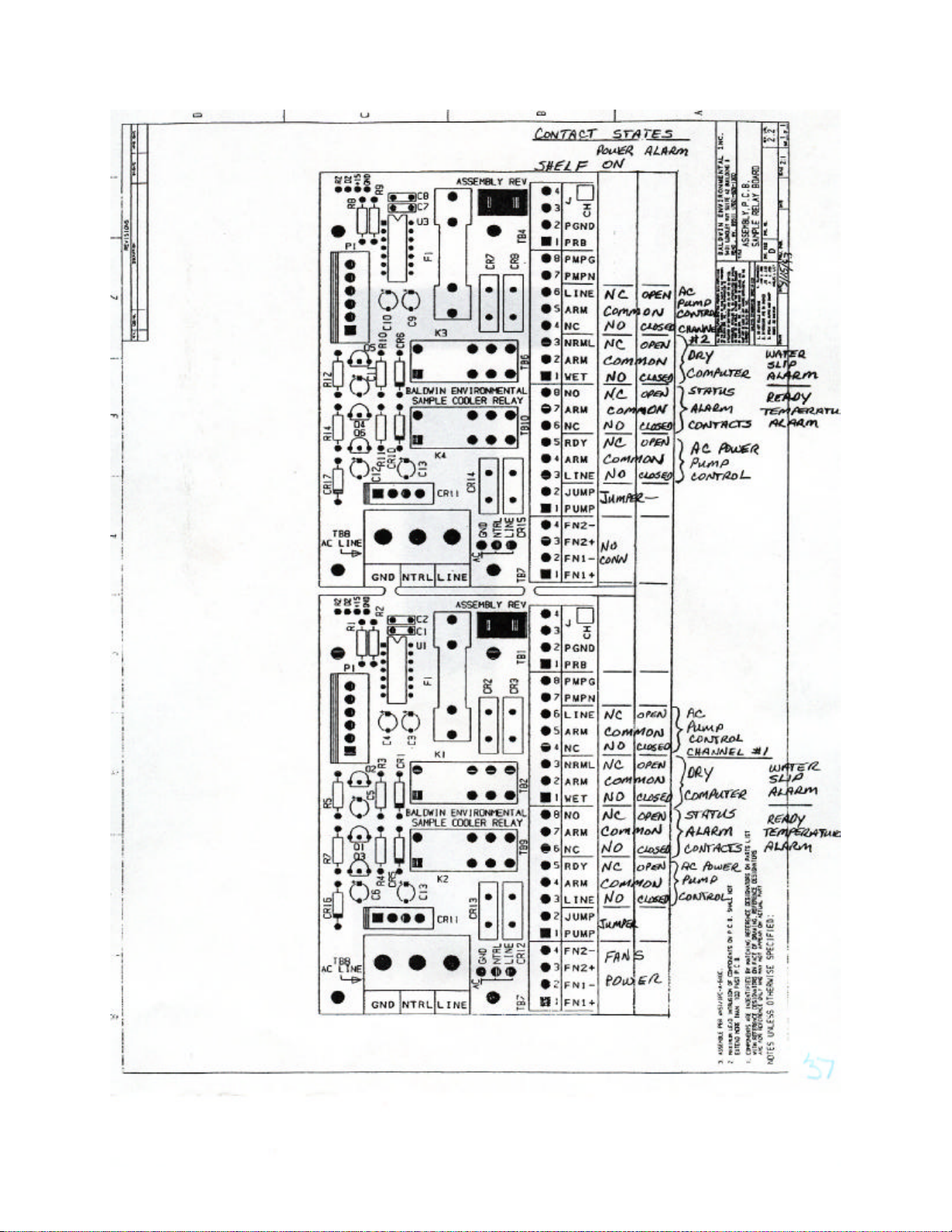
B3: Relay board contact state ....................................................................................... 17
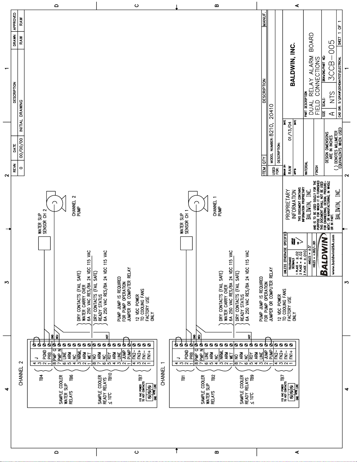
B4: Relay board field connections .................................................................................. 17
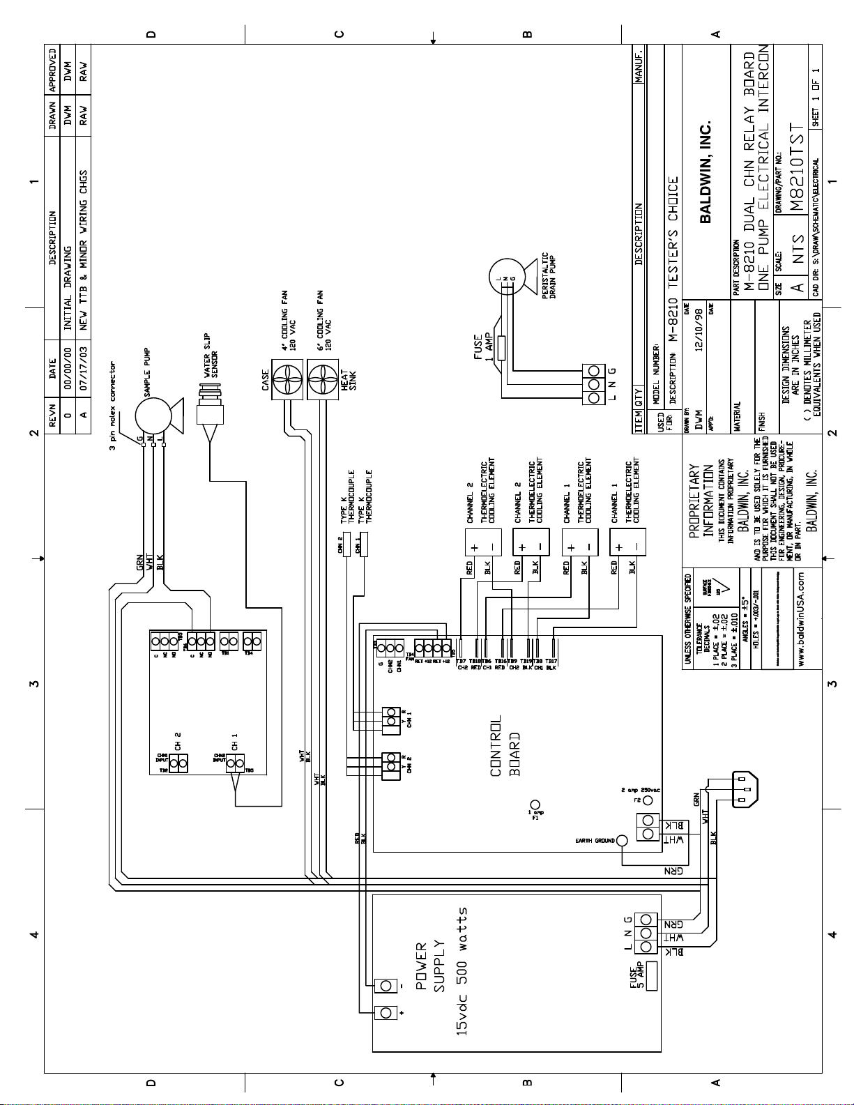
B5: Interconnect diagram ............................................................................................. 17
Appendix C: Perma Pure Sample Pump Maintenance Instructions........................................... 18
Appendix D: Dual Stream Operation .................................................................................. 19
Appendix E: Conversion Tables ......................................................................................... 20
Appendix F: Warranty and Disclaimer ................................................................................ 22
Page 3

PERMA PURE LLC
Model M8B User’s Manual
Doc. #580: Revision: 000
Page 3 of 22
Unpacking
Perma Pure has made every effort to ship you a high quality product that has been thoroughly
inspected and tested. It has been carefully packed to ensure that it arrives at your facility in good
condition. Even though every effort has been made to prevent damage during the transportation
process, damage can occur by the carrier. This is out of control of Perma Pure and is the
responsibility of the carrier to ensure that your equipment arrives intact and undamaged.
Inspect outside packaging. If there is any visible damage, inform the carrier at the time of
deliver. This inspection is important! Once the package is signed for, responsibility for
any visible damage then transfers to the consignee.
Unpack your equipment. Visually inspect the outside of your equipment for any damage. If
there is any damage, contact the carrier immediately. Generally, a carrier must be notified
within 24 hours of the delivery to make a hidden damage claim.
Items in the carton include:
(1) Model M8B – Testers’ Choice Portable Sample Conditioning System
(1) Power cord
(1) User’s manual
If any of the above parts are missing or damaged, call the helpline at (800) 337-3762 ext-145.
Introduction
Thank you for purchasing this product from Perma Pure LLC. This manual has been assembled so
that it can answer all questions regarding operation. Please keep the operators manual near the
equipment for future reference. There may also be optional equipment available that was not
ordered at the time of original purchase, which may be described and/or illustrated in this manual.
If you still have any questions regarding your equipment’s operation, available options or technical
support, please contact your purchasing dealer or contact Perma Pure directly.
Perma Pure LLC Tel: 732-244-0010
P.O. Box 2105 Tel: 800-337-3762 (toll free US)
8 Executive Drive Fax: 732-244-8140
Toms River, NJ 08754 e-mail: [email protected]
website: www.permapure.com
The Testers Choice Portable Sample Conditioning System can be either used for intermittent or
continuous operation. It is designed for accurate, repeatable and precise gas sample conditioning
that can be effectively carried out nearly anyplace and at anytime. This unit is also designed to
require only a minimum amount of maintenance to maximize its operation.
3
COPYRIGHT 2008, ALL RIGHTS RESERVED
Page 4
Model M8B User’s Manual
Doc. #580: Revision: 000
Page 4 of 22
PERMA PURE LLC
General description
The Perma Pure/Baldwin Tester’s Choice Model M8 Thermo-Electric cooler features a complete gas
conditioning system in one easy to manage enclosure. The unique design leaves additional space to
install or access other sample conditioning system components. A unique drop-down door on the
M8 cooler section, provides easy access to electronic boards and the power supply. All electronic
boards (control, relay, and display) are mounted on the door of the cooler for easy access. Sample
pump and peristaltic drain pump(s) are also mounted within the enclosure.
The process of sampling combustion
product stack gas or exhaust from internal
combustion engines requires a method to
remove the moisture from the sample,
without removing the gas components of
interest. The Tester’s Choice M8 System is
an ideal way to decrease the dew point of
combustion gases to a repeatable, stable,
constant low dew point. The Tester’s Choice
M8 system prevents water condensation in
sample pre-filters, sample pumps, and gas
analyzers. For gas analyzers where water
vapor is an interferent, a stable, repeatable,
dew point, becomes a part of the gas
analyzer performance specification. The
Tester’s Choice system provides this
constant low water concentration, resulting
in an accurate component gas
measurement.
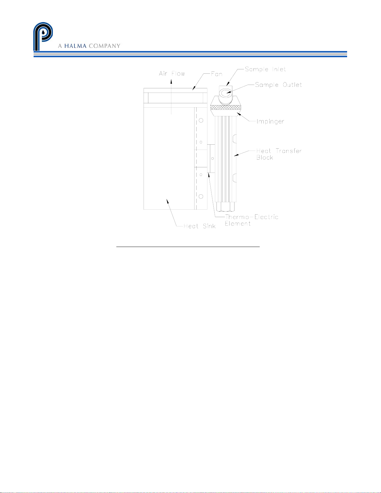
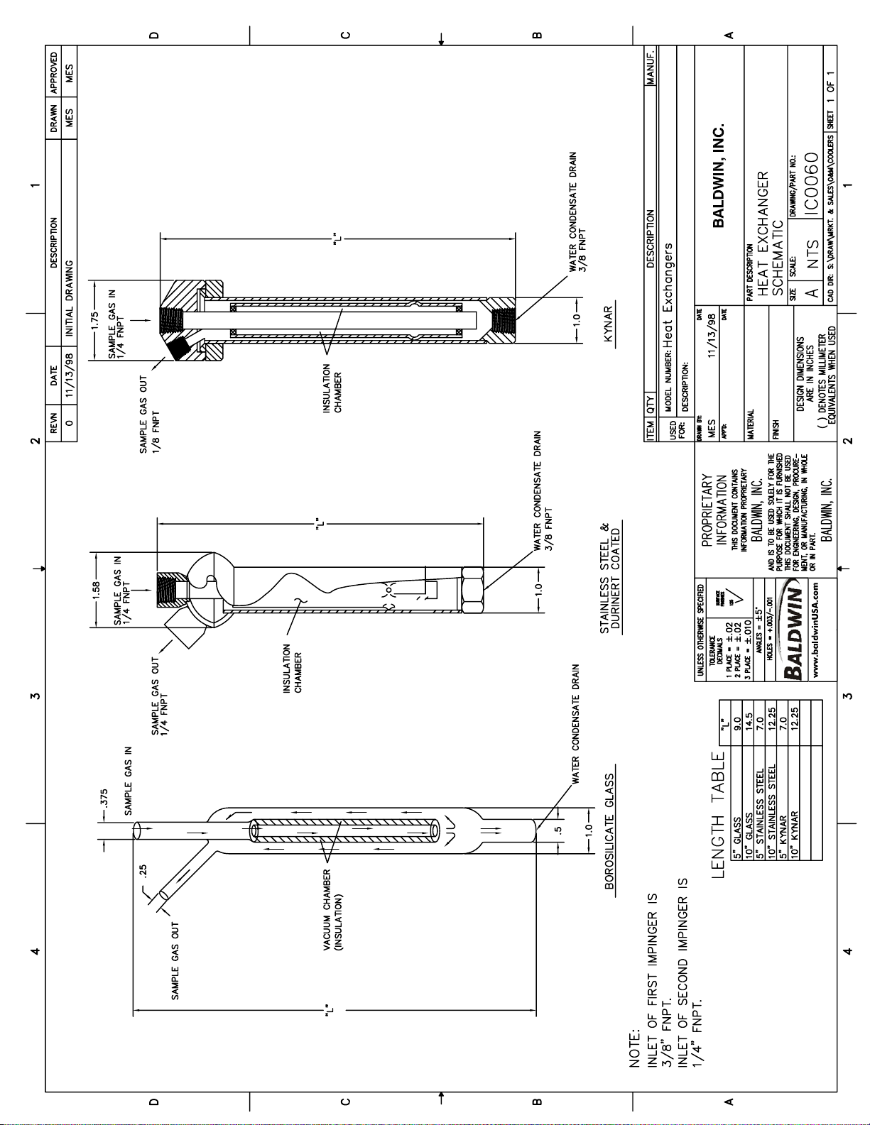
The Tester’s Choice M8 system removes the moisture from the sample gas by cooling the gas as it
passes through a laminar impinger (heat exchanger). A diagram showing the gas flow path through
an impinger is shown in the Appendix B2. The impinger, made of 316L stainless steel, Durinert
corrosion-resistant inert coating over 316L stainless steel), PVDF (Kynar®), or glass, is mounted
within a thermally insulated heat transfer block bored to receive the impinger without a mechanical
lock. This assembly allows the easy removal of any impinger simply by slipping it out of the cooling
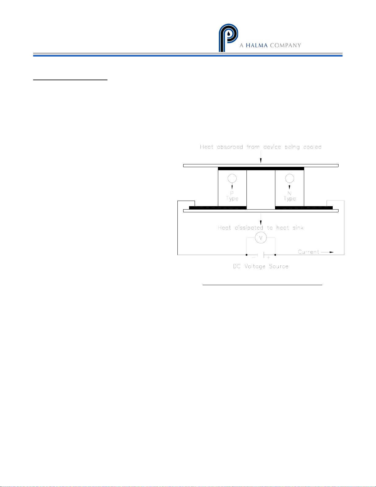
block by hand. The heat transfer block cools the heat exchanger through the heat pumping action
of the Peltier element. The heat transfer block is on the cold side of the thermo-electric element
and the heat sink is on the hot side of the thermo-electric element. The desired temperature is
maintained by a closed loop control system, which is implemented through an analog proportional
controller. The controller uses a type K thermocouple as a sensor.
Figure 1: Thermo-electric element (Peltier)
®
(a
Page 5
PERMA PURE LLC
Model M8B User’s Manual
Doc. #580: Revision: 000
Page 5 of 22
The Tester’s Choice M8 system will reduce the sample gas dew point to 5
Liters Per Minute (LPM). This is slightly above the temperature that the condensate removed from
the gas stream will freeze. If the condensate freezes sample analysis and gas stream flow will be
compromised.
If a lower dew point is necessary, a Perma Pure LLC Supplemental Drying System (S.D.S.) may be
necessary. A sample gas stream that contains significant amounts of SO3 may also be
encountered. Perma Pure LLC/Baldwin can supply SO3 Aerosol Removal Systems, specifically for
this purpose.
Please contact Perma Pure LLC for suggestions on alternative devices. Perma Pure LLC has a
system and expertise that can handle nearly any sample conditioning application.
Figure 2: Heat Exchanger, Impinger and Heat Sink
°
C at a maximum flow of 8
5
COPYRIGHT 2008, ALL RIGHTS RESERVED
Page 6

Model M8B User’s Manual
Doc. #580: Revision: 000
Page 6 of 22
Physical Description
• Two channel system
• 2 x 10” heat exchangers connected in series or parallel
• 2 Active (cooled to 5°C) heat exchangers
• LCD temperature display and LED status indicators
• Dimensions: 14.5” x 11” x 10.5” HWD (37 x 28 x 26.5 cm)
• Weight: 53 lbs (24 kg)
Specifications
Sample gas flow range Up to 8 LPM (17 scfh)
PERMA PURE LLC
Water content 20% H
Maximum cooling rate 440 BTU/ht (464 kJ/hr)
Maximum inlet sample temp. 400°F (205°C) for SS or glass impingers
280°F (138°C) for Kynar™ impingers
Maximum inlet pressure 15 psig (1 bar)
Maximum pressure drop <+1 in H2O
Ambient temperature range 33-114°F (0.6-43°C)
Outlet sample gas dew point 41°F (5°C)
Voltage 115VAC (230VAC optional)
50/60 Hz
Power supply 1000W
Cooling down time Less than 10 minutes
O (60°C DP)
2
Connections
• Sample gas inlet: Kynar, 1/4” tube compression fitting
• Sample gas outlet: Kynar, 1/4” tube compression fitting
• Drain tubing connection: Kynar, 1/4” barbed tube fitting
Page 7

PERMA PURE LLC
Model M8B User’s Manual
Doc. #580: Revision: 000
Page 7 of 22
Important Safety Warnings
Please be sure to review the following basic safety procedures. These procedures
represent the MINIMUM requirements to operate the equipment safely. It is the ultimate
responsibility of the operator to ensure proper safety practices are utilized at the point
of operation.
• NEVER
• NEVER
ratings must be closely observed and not exceeded. Voltage rating of the equipment MUST
the rating on the data label. Please make sure that it matches before powering up the equipment.
• This equipment is NOT
• This equipment is NOT
• Condensate is potentially dangerous.
item that may have come in contact with the gas stream or any hazardous material, without
adequate personal protective equipment. ALWAYS
• Sample gas is potentially dangerous.
often as necessary to maintain a safe working environment around the equipment. The gas stream
exhaust must exit away from all personnel to prevent dangerous exposure.
• NEVER operate the equipment with any part of the enclosure unsecured.
doors and covers must be in place and secured prior to operation. Electrical current may be present
behind covers or doors, even if tools are not necessary to access these components.
• NEVER
Repair of this equipment should only be done by properly trained personnel that are familiar with
the potential risks involved with servicing of this equipment.
• NEVER
bypass this, or any, safety device.
• NEVER
been damaged.
• The use of components that have not been purchased through an authorized Perma Pure LLC
dealer or directly from Perma Pure LLC may compromise the safety of the operator. Additionally,
use of non-authorized components may change the operating characteristics of this equipment.
Any changes to the equipment, that modify its operation in any way, are dangerous, and are
strictly prohibited.
• Read the entire operating manual before attempting to set up or operate the equipment.
• Please heed all warning labels that are on the equipment. They are there to remind you of
possible hazardous conditions.
• Verify the integrity of any mechanical and/or electrical connections that are made to the Testers
Choice Portable Sample Conditioning System.
attempt to operate this equipment in an explosive or otherwise hazardous area.
exceed any specified rating for the equipment. Voltage, temperature and pressure
match
designed to be used in an explosive environment.
designed to operate in a wet environment.
Never handle drain lines, impingers or any other
assume that any liquid present is hazardous.
A leak test is recommended at initial startup and as
All operated
attempt service on this equipment without first disconnecting all energy sources.
replace fuses with types other then the same specification of type and current. Do not
operate this equipment if it is visibly damaged or the possibility exists that it may have
o Verify that the unit is connected to the proper rated power for the system
o Verify that the unit is plumbed properly to operate effectively
o Do not block either the cooling air inlet or outlet on the rear of the cabinet. The
efficiency of the unit will be compromised and long term use in this condition could
permanently damage the cooling system.
7
COPYRIGHT 2008, ALL RIGHTS RESERVED
Page 8
Model M8B User’s Manual
Doc. #580: Revision: 000
Page 8 of 22
PERMA PURE LLC
Connection & Start-up
The Classic Tester’s Choice portable sample conditioning system should be set up away from
any heat sources in a well vented area.
The system can only be operated in an upright position. The conditioning system must not be
set up at an angle greater than 30° from vertical.
NOTE: The operational stability of the cooler dew point is influenced by the
stability of the ambient temperature.
For proper operation, the ambient temperature cannot exceed 43°C (110°F). At, or close to the
maximum ambient temperature, the cooler will not be able to control the temperature to
reduce the dew point of the sample gas to the 5°C set point. This will result in compromised
operation and water slip or carryover, possibly into the analyzer.
The Tester’s Choice portable sample conditioning system can be either used for intermittent or
continuous operation. It is designed for accurate, repeatable and precise gas sample
conditioning that can be effectively carried out nearly anyplace and at anytime. This unit is also
designed to require only a minimum amount of maintenance to maximize its operation.
Sample and Drain Connections
1. Connect a suitable condensate drain line to the connector on bottom of unit.
NOTE: Do not reduce the size of the condensate tubing since doing so restricts water
flow resulting in water carryover into the sample.
2. Run the external drain line to appropriate drain receptacle.
Drain condensate can be potentially hazardous. Always make sure that proper
precautions are taken regarding personal protective equipment when handling
condensate.
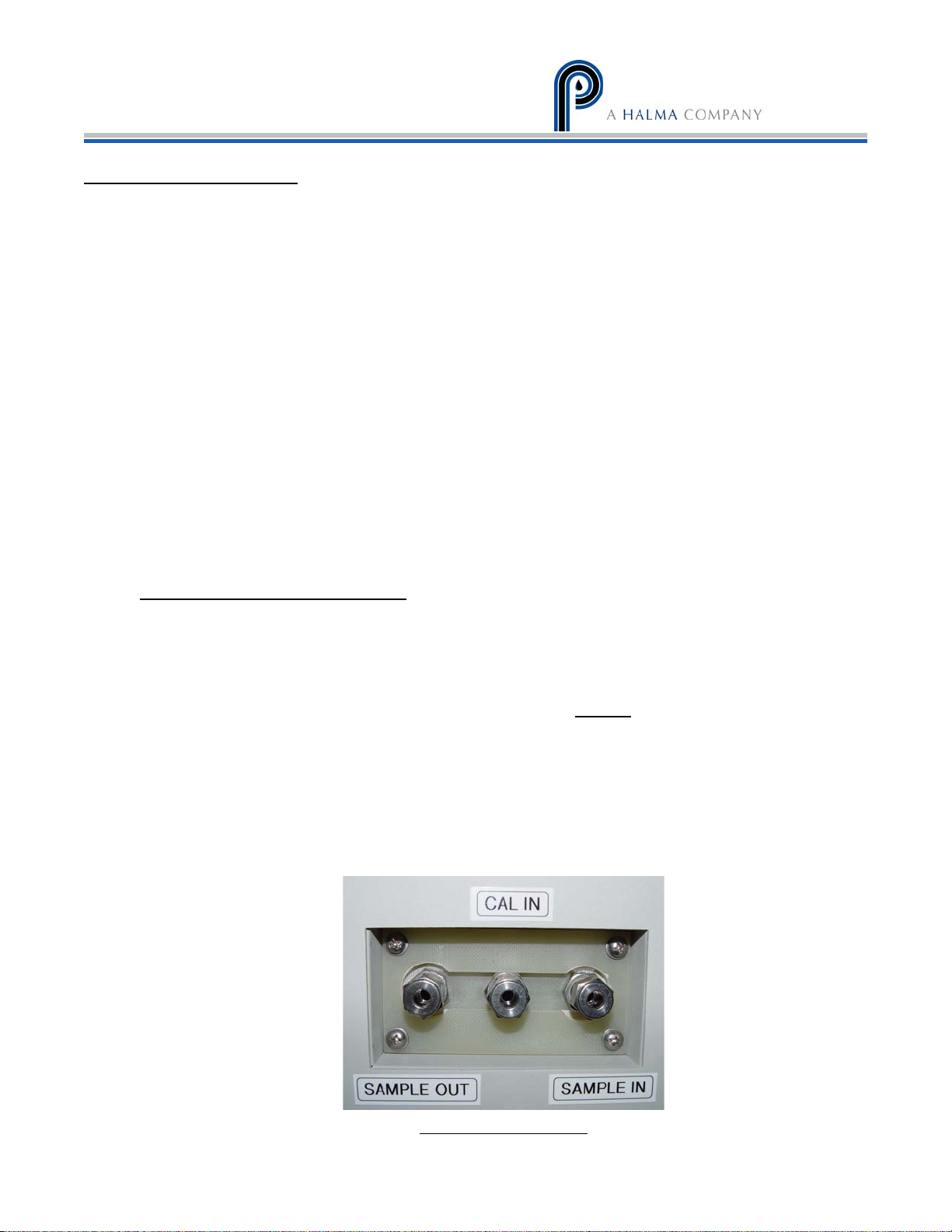
3. Connect the sample line to the stainless steel sample inlet compression fittings on the
rear of the unit. See figure 3.
NOTE: If using stainless steel sample line, place 2 inches of Teflon tubing in between
the exchanger inlet fitting and the heated line. This prevents the sample cooler from
heat sinking the incoming heated line, which adds undue load to the cooler.
Figure 3 - Gas connections
Page 9

PERMA PURE LLC
Model M8B User’s Manual
Doc. #580: Revision: 000
Page 9 of 22
The Tester’s Choice M8 will condition a single gas stream in its standard
configuration only. A second, parallel gas stream connection and the associated
hardware are available as an option. If this option was purchased, see Appendix D
for instructions.
4. Connect the conditioned sample outlet connector to the sample gas line leading to the
analyzer.
5. Connect the supplied power cord to the receptacle on the rear of the unit. See figure 4.
Figure 4 - Power connection
Do not power up the unit at this time. Verify that the proper supply voltage is available to
power the Tester’s Choice M8.
9
COPYRIGHT 2008, ALL RIGHTS RESERVED
Page 10
Model M8B User’s Manual
Doc. #580: Revision: 000
Page 10 of 22
PERMA PURE LLC
LED Summary
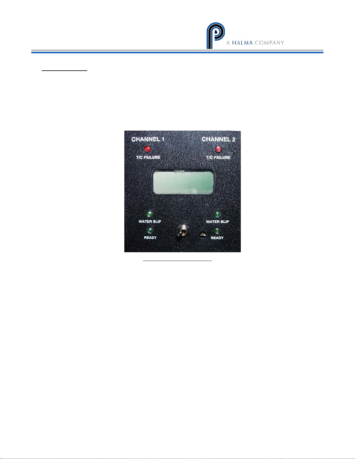
The controls for the M8 cooler are visible through the main door’s window. The M8 is a two
channel cooler that can flow up to 8 LPM of a gas stream, reducing the dew point to 5°C or less.
There are several indicators and a display to provide operational information on the status of
the cooler. The temperature of either channel can be selected and viewed on the LCD display.
Simply move the toggle switch on the front panel in the direction of the channel, to display the
temperature on the LCD.
Figure 5 - Front display panel
There are 2 sets (one for each impinger) of 3 LED status displays, 1 red and 2 green. These
indicators are arranged vertically on the front of the cooler. See figure 5.
● “Failure” Red LED comes on if the
thermocouple or an electronic controller
component has failed.
● “Slip” Green LED comes on when powered up.
● “Ready” Green LED comes on when the ready
set-point temperature (+10°C) is reached.
NOTE: “Slip” LED is connected to the water slip sensor, which is normally dry on start up. If the
“Slip” Green LED goes out, this indicates water is “slipping” past the heat exchanger. The relay
then shuts off the sample pump so that water is not allowed to reach the analyzers, preventing
damage to the analytical instruments. Steps need to be taken at this time to determine the
cause of the moisture and correct the situation.
The sample pump will begin operating once the green READY indicators are both lit.
Page 11

PERMA PURE LLC
Model M8B User’s Manual
Doc. #580: Revision: 000
Page 11 of 22
Start-up
The gas sample pump is controlled and will operate only under certain conditions. The sample
pump will only be allowed to run if the temperature is 10°C or less AND the water slip sensor
indicators are green.
The peristaltic drain pumps will run continuously anytime Tester’s Choice is energized.
Now that there is a complete understanding of all of the controls and indicators, please verify that
all of the connections to the Testers Choice M8 are correct. Once this re-check has been completed,
please energize The Testers Choice M8. The unit should be ready to operate and begin the sample
conditioning process after operating for about ten minutes.
1. Plug power cord into a properly grounded main circuit. Green “Slip” LED will come on.
2. Wait for the green “Ready” LED light to come on, approx. 3 minutes. This will indicate the
ready temperature (+10°C) has been achieved and the sample gas flow can begin.
3. After approx. 3 more minutes, the factory set-point of +5°C (41°F) or less will be reached.
The SLIP Green LED is always on unless;
• Moisture is detected by the water slip sensor
• The cooler was ordered without a relay board
• There is a malfunction (eg. Shorted water slip sensor leads or a bad relay board)
11
COPYRIGHT 2008, ALL RIGHTS RESERVED
Page 12
Model M8B User’s Manual
Doc. #580: Revision: 000
Page 12 of 22
PERMA PURE LLC
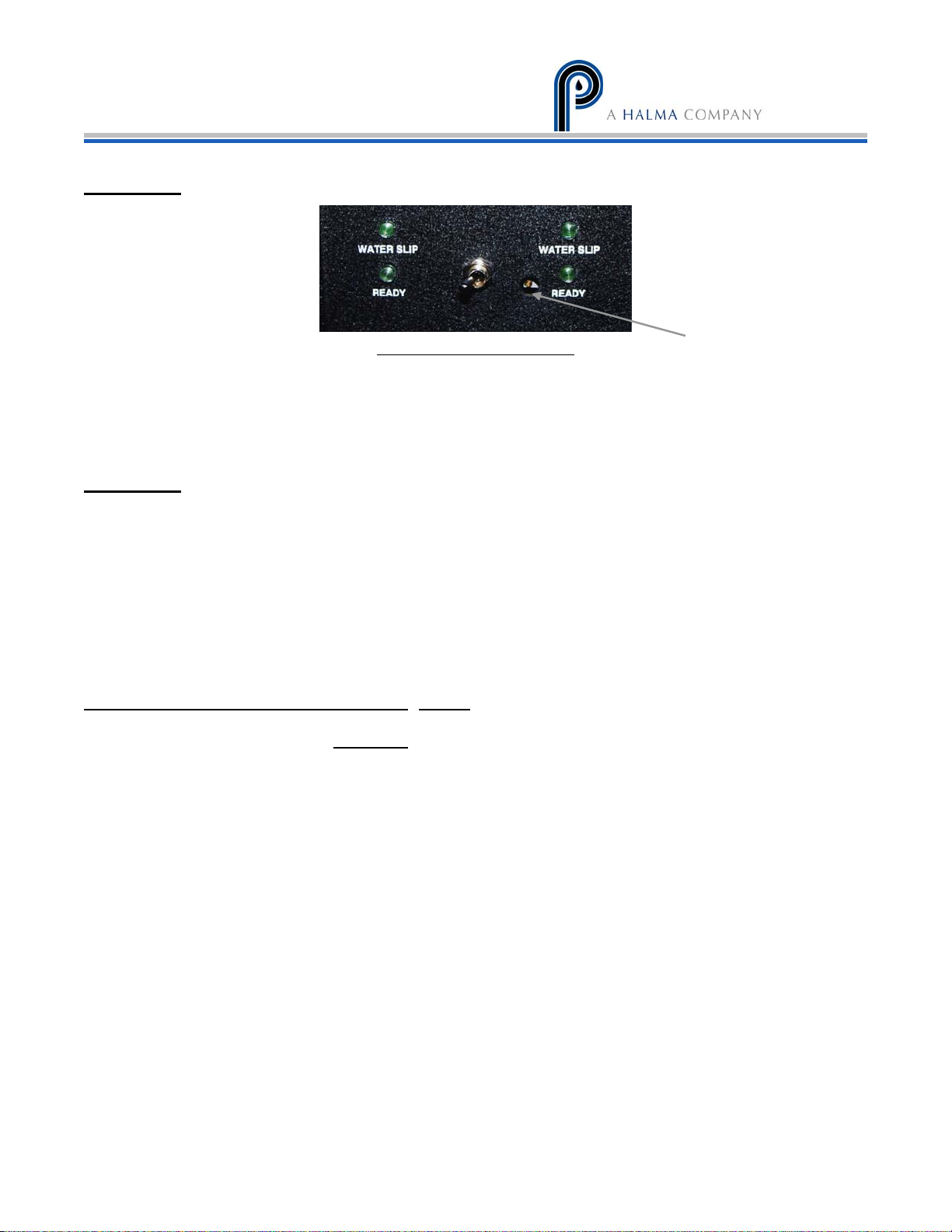
Set Points
The set point potentiometers are factory set and sealed for proper cooler operation.
Consult the factory before making any changes to these set point adjustments.
Figure 6 - Set point adjustment
Potentiometer
Shutdown
After completion of operation with a gas stream, allow the Testers Choice to run for at least 10
minutes with both Sample In and Sample Out connections open to atmosphere. This will allow
the inlet and outlet lines a sufficient amount of time to evacuate any moisture in the system. If an
overly high dew point sample was introduced to the system it may be beneficial to allow the
system to run longer. In any case it is always a good practice to make sure that all of the
condensate is drained from the impingers, drain lines and peristaltic pumps. Visually observing the
condensate drain, while the peristaltic pumps are running, is good practice to ensure that
condensate is completely removed from the system. This should be done before disconnecting the
drain hose from the system.
Condensate is potentially dangerous.
that may have come in contact with the gas stream or any hazardous material, without adequate
personal protective equipment. ALWAYS
After the Testers Choice M8 has been run for a period of time, it is possible that a small amount of
clean water may puddle in the bottom of the cabinet. This moisture is a byproduct of the thermoelectric coolers operation and may come from the cooling block assembly’s outer surface. The
surface temperature of the cooling block, which has gone below the ambient air dew point, may
cause condensation to drip to the bottom of the cabinet. This is a normal situation, but doesn’t
always occur. Any water inside of the cabinet should be removed before transporting the unit to a
different location.
Never handle drain lines, impingers or any other item
assume that any liquid present is hazardous.
Page 13

PERMA PURE LLC
Troubleshooting and Maintenance Guide
Model M8B User’s Manual
Doc. #580: Revision: 000
Page 13 of 22
Symptom
Diagnostic Fix
No LED(s) and no fan. AC power input. Ensure that AC power is
connected.
No LED(s) and fan on. AC input fuse on control board.
DC output fuse on control board.
LED(s) on and no fan. AC input fuse on power supply.
+15vdc TB4 on control board.
Impinger remains at
ambient temperature.
Thermocouple failure LED
is on.
Impinger frozen and cooler
indicates ambient
temperature.
Impinger does not reach
set temperature, but is
below ready temperature.
Impinger temperature
cycles up and down.
Ready LED does not come
on when impinger is below
7°C.
Water Slip (carryover) in
system.
Slip LED does not come on
(alarm relay/water slip
option installed).
Peltier current draw. Should be
above 6 amps when first turned
on.
If unit has two active impingers,
switch Peltier element connections
to other channel
Thermocouple connection TB1, 2. Ensure proper connection to
Thermocouple placement in heat
exchanger block.
System loading.
Calibration and Set temperature
adjustment.
Peltier connections on control
board.
Ready temperature adjustment. Consult with Perma Pure Tech
Impinger temperature. Should be
below 6°C.
Water slip sensor connections. Ensure that all water slip sensor
Replace fuse as necessary.
Replace fuse as necessary.
Replace fuse as necessary.
If not present, replace power
supply.
If lower than 6 amps or above 8
amps suspect that Peltier element
has failed.
If problem remains at same
channel, control board defective. If
it changes, Peltier defective
control board. If connection good,
replace thermocouple.
Ensure proper placement. Replace
thermocouple or control board.
Ensure system loading is not
exceeding cooler capacity.
Consult with Perma Pure Tech
Support
Ensure a firm connection on flag
connectors on control board.
Ensure system loading is not
exceeding cooler capacity.
Support.
Ensure system loading is not
exceeding cooler capacity.
Ambient must not exceed 45°C
(113°F)
connections are made.
Clean tip of sensor.
Replace alarm relay/water slip
board as needed.
13
COPYRIGHT 2008, ALL RIGHTS RESERVED
Page 14

Model M8B User’s Manual
Doc. #580: Revision: 000
Page 14 of 22
PERMA PURE LLC
Sample pump does not
start. Ready and slip
LED(s) are on (alarm
relay/water slip option
installed).
Sample pump does not
start.
Ready LED is on;
Slip LED is Off
(alarm relay/water slip
option installed).
Sample pump starts. No
sample stream.
Ready LED is on;
Slip LED is ON (green)
(alarm relay/water slip
option installed).
Water carryover in system
Ambient air temperature too high
Operation of peristaltic pump(s) or
eductor
Heat sink cooling fan and heat sink
air flow path
Air leaks in sample line
Electrical connections to sample
pump
Sample line connections
Verify that flow meter needle is
not seated
Filter element
Sample line clogged or deformed
Sample pump suction/ pressure
Clean water slip sensor and
restart. Ensure system loading
does not cause water slip
Ambient must not exceed 43°C
(110°F)
Verify that pump or eductor is
draining condensate from
impingers; Replace pump/hoses as
necessary
Fan and air path need to flow
proper amount of air. If debris is
clogging air path or fan is not
functioning properly, unit will loose
efficiency
Verify that there are no air leaks at
any point in the sample line.
Ambient air entry either on the
pressure or vacuum side of the
sample pump will cause excess
condensate and could lead to
water slip.
Verify that proper voltage is
reaching pump.
If voltage is good, replace pump
If voltage is not present, check for
voltage at relay board; if not
present consult with Perma Pure
Tech Support.
If voltage present trace out wiring
issue.
Verify proper connections.
Adjust as necessary
Check for clogged filter. Replace
element if necessary.
Unclog, reform/replace as
necessary
Sample pump valve
discs/gaskets/diaphragm have
reached the end of service life.
Replace as necessary. Consult with
Perma Pure Tech Support
Page 15

PERMA PURE LLC
Model M8B User’s Manual
Doc. #580: Revision: 000
Page 15 of 22
Replacement Parts
Part No. Description
2FAN-007 Fan: muffin, 6” x 1-1/2”, 12 VDC
2FAN-009 Fan: muffin, 3” x 2”, 12 VDC
3CXD-022 Impinger: 10" EZ-clean twist-apart stainless steel Durinert
3CXG-002 Impinger: 10” Glass, threaded w/ fittings
3CXK-003 Impinger: 10” Kynar
3CXS-022 Impinger: 10” Stainless steel, EZ-clean twist-apart
3KPE-004* Peltier element Kit, 40 mm, single TE
3CCB-019* Control board: dual channel
1PSD-009* Power Supply: 500 W, 15 VDC
3CCB-018* Alarm Board: Dual Channel
3TCB-002 Temperature control board, dual channel
1TTC-003 Thermocouple: Temperature, Control, Type K, 36”
3KFA-001 Complete filter assembly, sample in-line, 2-micron
3FHG-001 Filter bowl, glass
3FEC-002** Filter element: ceramic, 2-micron
3KPB-003 Peristaltic pump: dual, kit, 115V complete w/ enclosure
3KPB-004 Peristaltic pump: dual, kit, 230V complete w/ enclosure
2PBM-003 Peristaltic pump: head only, standard
2PBM-001 Peristaltic pump: motor only, 115V AC 60 Hz
2PBM-006 Peristaltic pump: dual head, hardware Kit
2PBT-002PK* Peristaltic pump: Tubing, Norprene, Size 17 (10 feet)
3KPA-002* Sample pump: assembly, dual head w/ check valve, 115V
3KPA-005* Sample pump: assembly, dual head w/ check valve, 230V
2PAM-002* Sample pump: repair kit, dual head
3CWS-007 Water slip sensor only with 18” leads
3KCW-007 Water slip sensor (SS pins) w/ holder assembly, ¼” Kynar fittings
* Recommended Spares **Consumables
®
15
COPYRIGHT 2008, ALL RIGHTS RESERVED
Page 16
Model M8B User’s Manual
Doc. #580: Revision: 000
Page 16 of 22
PERMA PURE LLC
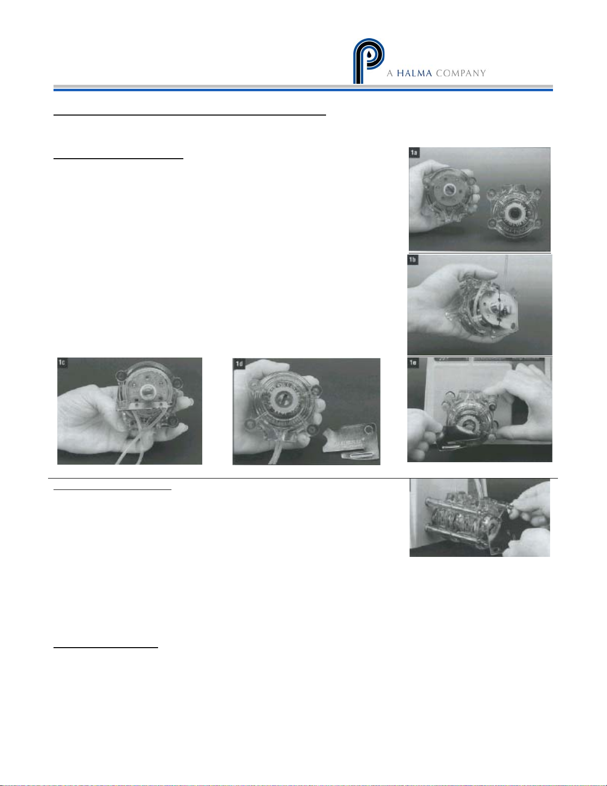
Appendix A: Installation of Peristaltic Pump
NOTE: Perma Pure peristaltic pumps are rated for a maximum pressure of 20 psi.
If supplied loading key is not available, use a flat head screwdriver.
Single pump head loading
a) Separate the end bells (the pump head halves). Hold the end bell containing the
rotor as shown with the tubing retainer grooves facing down.
b) Place tubing in the right groove and against the first two rollers. Hold tubing
with thumb. Near groove, insert smaller prong of loading key between the top of
the rotor and tubing. Push key in as far as possible.
c) Push down and turn key counterclockwise completely around the rotor. The key
will push the tubing uniformly into the end bell assembly. Hold the second end of
the tubing. Remove key.
d) Position the other end bell on top and press the end bells together. Be careful
not to pinch the tubing. If end bells do not snap tightly together, reload tubing.
If necessary, turn key in slot on rotor shaft to adjust tubing (as in step e).
e) With key in slot on rotor shaft, turn key to align tang on rotor shaft with slot in
motor drive shaft. Point tubing retainer grooves up. Shift the pump head slightly
till it snaps on the alignment pins (if present). Secure with four provided screws.
Tighten with fingers only.
Multi-channel mounting
a) Load the pump heads with tubing.
b) Install the four correct length mounting screws in drive.
c) Slide the first pump head into the mounting screws.
d) Place key in slot on mounting shaft. Twist to align tang on rotor shaft with slot in motor drive shaft. Shift the pump
housing around till it drops over the alignment pins (if present).
e) Repeat for each additional pump head, aligning pump head tang with slot on previously mounted pump head.
f) Slide the flow flat washers onto screws and secure with the four wingnuts. Tighten with fingers only.
Replacement parts
2PBM-001 Peristaltic pump, motor only, 115 VAC 60 Hz
2PBM-002 Peristaltic pump, motor only, 230 VAC 50 Hz
2PBM-003 Peristaltic pump, head only, standard
2PTB-002PK Peristaltic pump, tubing, Norprene, size 17 (10 feet)
2PBM-006 Dual head hardware kit
Page 17

PERMA PURE LLC
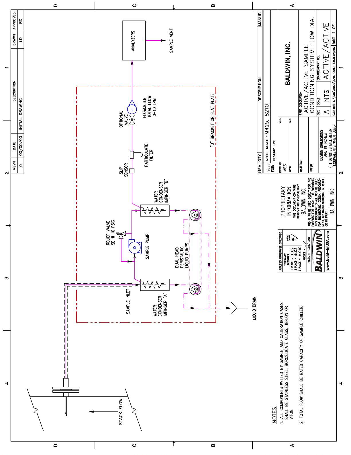
Appendix B: Drawings
B1: 4S-M8 flow diagram
B2: Impinger schematic
B3: Relay board contact state
B4: Relay board field connections
B5: Interconnect diagram
Model M8B User’s Manual
Doc. #580: Revision: 000
Page 17 of 22
17
COPYRIGHT 2008, ALL RIGHTS RESERVED
Page 18
Page 19
Page 20
Page 21
Page 22
Page 23
Model M8B User’s Manual
Doc. #580: Revision: 000
Page 18 of 22
PERMA PURE LLC
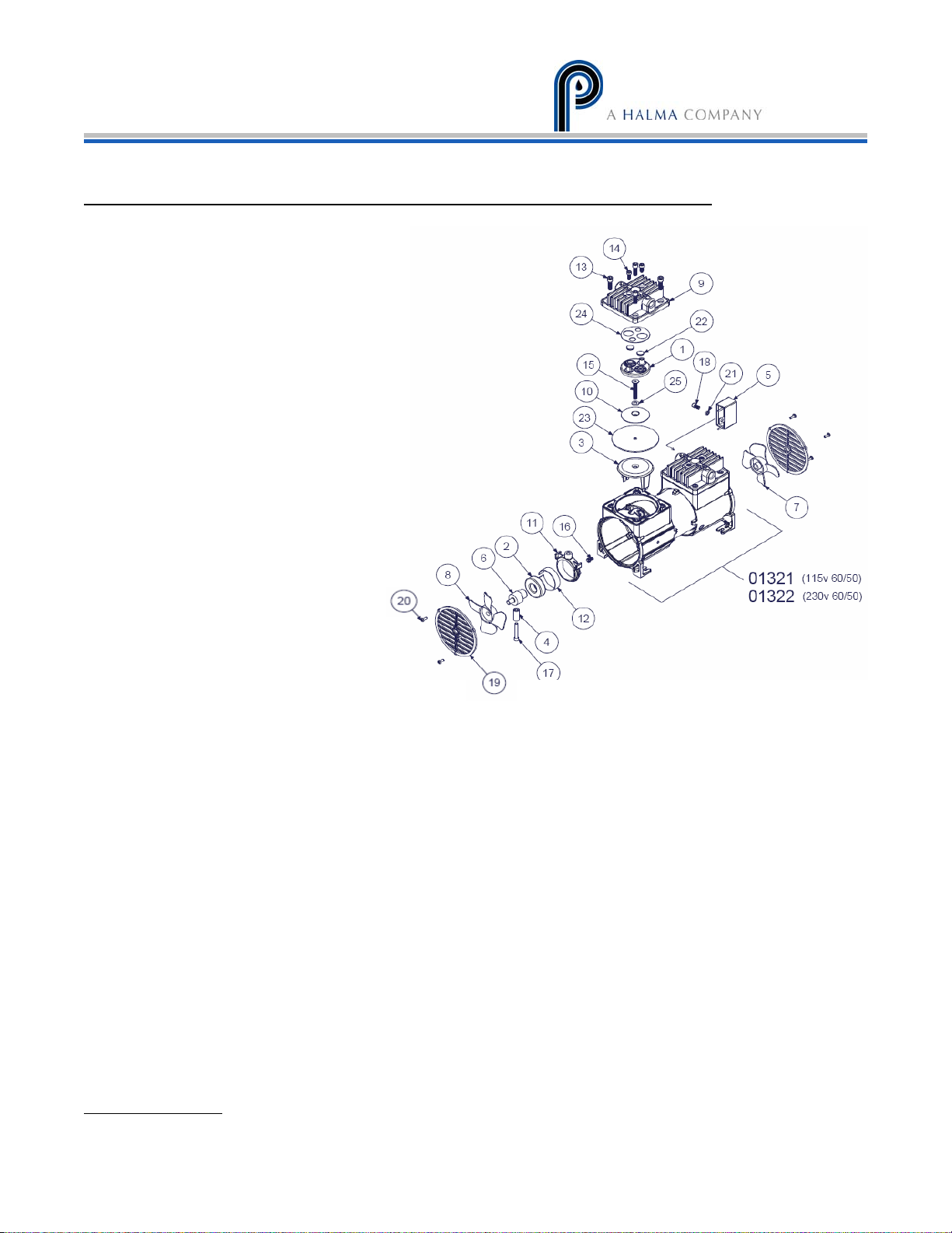
Appendix C: Perma Pure Sample Pump Maintenance Instructions
Item # Description
VALVEBODY
1
BEARING
2
CAP
3
CWEIGHT
4
CAPACITOR
5
ECCENTRIC
6
FAN, BLUE
7
FAN, WHITE
8
HEAD STD, SS
9
PLATE DIAPH.
10
CONNECTING ROD
11
TOL. RING
12
SCREW-HEAD/BASE
13
SCREW
14
PLATE SCREW
15
GROUND SCREW
16
SCREW
17
SCREW
18
SCREEN
19
SCREW
20
LOCK WASHER
21
DISC-VALVE
22
DIAPHRAGM
23
GASKET
24
WASHER
25
Disassembly of head section and service diaphragm
1. Remove head section by unscrewing the four large bolts. A flat-bladed screw driver may be needed to
gently pry the head free of the service diaphragm. If you have Teflon coating on the heads, use
caution not to scratch the surface.
2. The valve body can then be removed by unscrewing the two smaller screws (also accessible on the top
of the head section). This part may be freed by gently tapping on these two screws after they have
been loosened about 3 or 4 turns. When the valve body is removed, check all internal surfaces fro an
accumulation of dirt. The two valve discs can be wiped clean and replaced as long as they appear
unaffected by usage. The valve gasket can be easily removed and should be inspected. As a matter of
good practice, the valve discs and valve gasket should be replaced during any routine maintenance
check of the head section. A once a year routing procedure is recommended.
3. The service diaphragm is secured by the single screw in its center. Remove this screw with a 5/32”
Allen wrench. The diaphragm and its clamping plate should be easily lifted off. Some slight adherence
to the metal may occur if the diaphragm has been in use for a long period.
4. When replacing the service diaphragm, a Teflon washer should be inserted under the head of the
diaphragm cap screw. This is added insurance against small gas leaks through screw heads and may
be essential in vacuum applications where outside air contamination cannot be tolerated. After
tightening the screw, the excess Teflon should be trimmed away.
5. NOTE: When replacing the service diaphragm, be sure the four projection studs of the base casting
are properly located in the four outer holes provided in the diaphragm before the part is clamped in
place. Be sure the diaphragm plate is firmly replaced with its center screw.
Replacement parts:
2PAM-002 Sample pump repair kit, dual head
Page 24

PERMA PURE LLC
Appendix D: Dual Stream Operation
The dual stream option was not purchased for this unit.
Model M8B User’s Manual
Doc. #580: Revision: 000
Page 19 of 22
19
COPYRIGHT 2008, ALL RIGHTS RESERVED
Page 25
Model M8B User’s Manual
Doc. #580: Revision: 000
Page 20 of 22
PERMA PURE LLC
Appendix E: Conversion Tables
CHART OF VOLUME PERCENT WATER CONCENTRATIONS AT SATURATION FOR VARIOUS
TEMPERATURES AT STANDARD PRESSURE (ATMOSPHERIC PRESSURE)
DEGREES C DEGREES F VOLUME % DEGREES C DEGREES F VOLUME %
+100
+ 90
+ 80
+ 75
+ 70
+ 65
+ 60
+ 55
+ 50
+ 45
+ 40
+ 35
+ 30
+ 29
+ 28
+ 27
+ 26
+ 25
+ 24
+ 23
+ 22
+ 21
+ 20
+ 19
+ 18
+ 17
+ 16
+ 15
+ 14
+ 13
+ 12
+ 11
+ 10
+ 9
+ 8
+ 7
+ 6
+ 5
+ 4
+ 3
+212
+194
+176
+167
+158
+149
+140
+131
+122
+113
+104
+ 95
+ 86
+ 84
+ 82
+ 81
+ 79
+ 77
+ 75
+ 73
+ 72
+ 70
+ 68
+ 66
+ 64
+ 63
+ 61
+ 59
+57
+ 55
+ 54
+ 52
+ 50
+ 48
+ 46
+ 45
+ 43
+ 41
+ 39
+ 37
100.00
69.20
46.70
38.70
30.70
25.20
19.70
15.50
12.20
9.45
7.25
5.55
4.19
3.95
3.73
3.62
3.32
3.13
2.94
2.77
2.61
2.46
3.31
2.17
2.04
1.91
1.79
1.68
1.58
1.48
1.38
1.29
1.21
1.13
1.03
0.988
0.922
0.861
0.803
0.751
+ 2
+ 1
0
-1
-2
-3
-4
-5
-6
-7
-8
-9
-10
-11
-12
-13
-14
-15
-16
-17
-18
-19
-20
-22
-24
-26
-28
-30
-32
-34
-36
-38
-40
-42
-44
-46
-48
-50
-52
-54
+ 36
+ 34
+ 32
+ 30
+ 28
+ 27
+ 25
+ 23
+ 21
+ 19
+ 18
+ 16
+ 14
+ 12
+ 10
+ 9
+ 7
+ 5
+ 3
+ 1
0
-2
-4
-8
-11
-15
-18
-22
-26
-30
-34
-37
-40
-44
-47
-51
-54
-58
-62
-65
0.696
0.649
0.602
0.555
0.510
0.469
0.431
0.396
0.363
0.333
0.305
0.281
0.256
0.234
0.214
0.196
0.179
0.163
0.148
0.135
0.123
0.112
0.102
0.084
0.069
0.057
0.046
0.038
0.031
0.025
0.019
0.016
0.013
0.011
0.008
0.006
0.005
0.004
0.003
0.002
Page 26
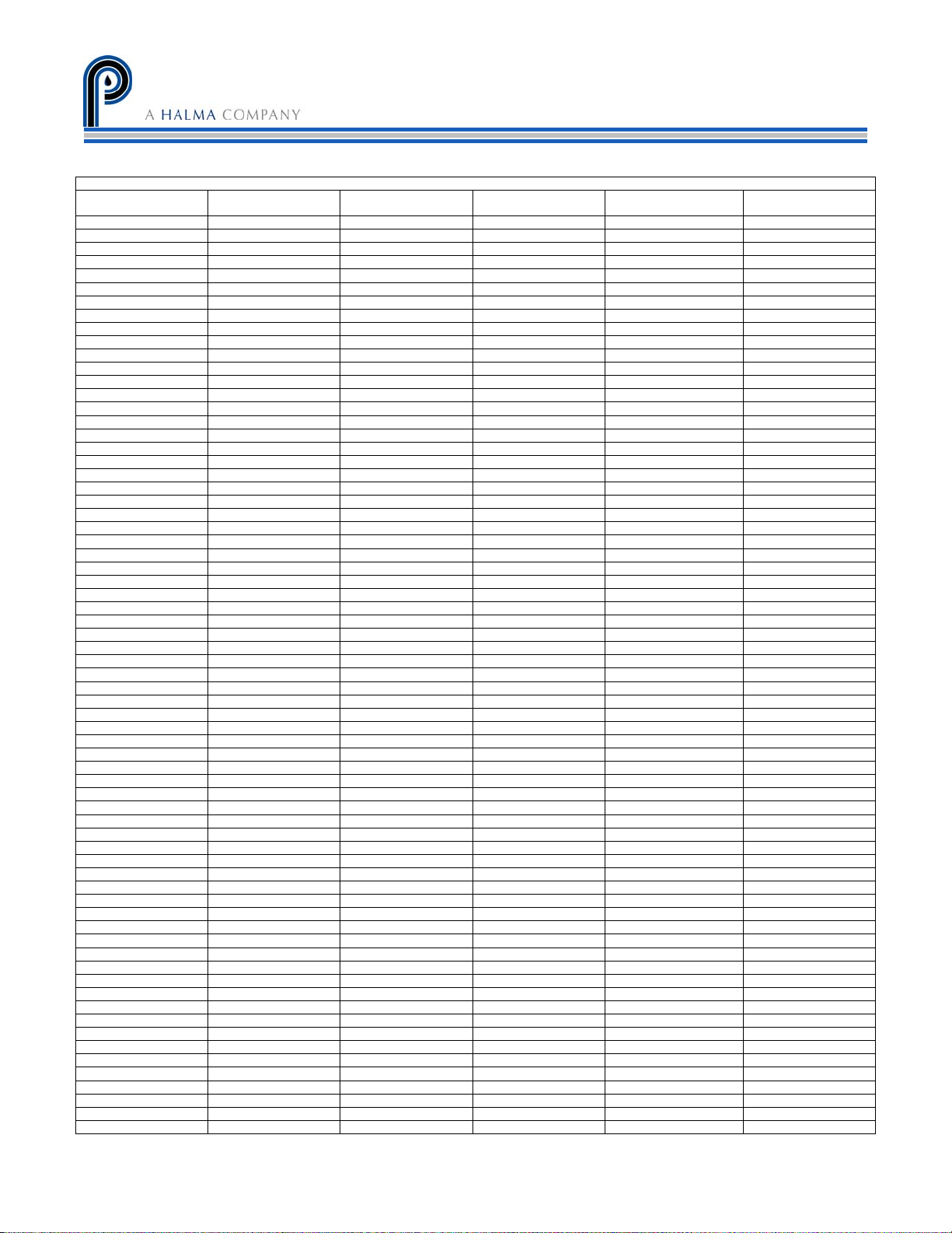
DEW POINT
PERMA PURE LLC
Model M8B User’s Manual
Doc. #580: Revision: 000
Page 21 of 22
°F
-110 -166 .0000010 .00132 .0000053 0.00082
-108 -162 .0000018 .00237 .0000096 .0015
-106 -159 .0000028 .00368 .000015 .0023
-104 -155 .0000043 .00566 .000023 .0035
-102 -152 .0000065 .00855 .000035 .0053
-100 -148 .0000099 .0130 .000053 .0081
-98 -144 .000015 .0197 .000080 .012
-96 -141 .000022 .0289 .00012 .018
-94 -137 .000033 .0434 .00018 .027
-92 -134 .000048 .0623 .00026 .039
-90 -130 .00007 .0921 .00037 .057
-88 -126 .00010 .132 .00054 .082
-86 -123 .00014 .184 .00075 .11
-84 -119 .00020 .263 .00107 .16
-82 -116 .00029 .382 .00155 .24
-80 -112 .00040 .562 .00214 .33
-78 -108 .00056 .737 .00300 .46
-76 -105 .00077 1.01 .00410 .83
-74 -101 .00105 1.38 .00559 .86
-72 -98 .00143 1.88 .00762 1.17
-70 -94 .00194 2.55 .0104 1.58
-68 -90 .00261 3.43 .0140 2.13
-66 -87 .00349 4.59 .0187 2.84
-64 -83 .00464 6.11 .0248 3.79
-62 -80 .00614 8.08 .0328 5.01
-60 -76 .00808 10.6 .043 6.59
-58 -72 .0106 13.9 .0565 8.63
-56 -69 .0138 18.2 .0735 11.3
-54 -65 .0178 23.4 .0948 14.5
-52 -62 .0230 30.3 .123 18.8
-50 -58 .0295 38.8 .157 24.1
-48 -54 .0378 49.7 .202 30.9
-46 -51 .0481 63.3 .257 39.3
-44 -47 .0609 80.0 .325 49.7
-42 -44 .0768 101 .410 62.7
-40 -40 .0966 127 .516 78.9
-38 -36 .1209 159 .644 98.6
-36 -33 .1507 198 .804 122.9
-34 -29 .1873 246 1.00 152
-32 -26 .2318 305 1.24 189
-30 -22 .2859 376 1.52 234
-28 -18 .351 462 1.88 287
-26 -15 .430 566 2.30 351
-24 -11 .526 692 2.81 430
-22 -8 .640 842 3.41 523
-20 -4 .776 1020 4.13 633
-18 0 .939 1240 5.00 770
-16 +3 1.132 1490 6.03 925
-14 +7 1.361 1790 7.25 1110
-12 +10 1.632 2150 8.69 1335
-10 +14 1.950 2570 10.4 1596
-8 +18 2.326 3060 12.4 1900
-6 +21 2.765 3640 14.7 2260
-4 +25 3.280 4230 17.5 2680
-2 +28 3.880 5100 20.7 3170
0 +32 4.579 6020 24.4 3640
+2 +36 5.294 6970 28.2 4330
+4 +39 6.101 8030 32.5 4990
+6 +43 7.013 9230 37.4 4730
+8 +46 8.045 10590 42.9 6580
+10 +50 9.029 12120 49.1 7530
+12 +54 10.52 13840 56.1 8600
+14 +57 11.99 15780 63.9 9800
+16 +61 13.63 17930 72.6 11140
+18 +64 15.48 20370 82.5 12650
+20 +68 17.54 23080 93.5 14330
+22 +71 19.827 26088 16699
+24 +75 33.377 29443 18847
+26 +79 25.209 33169 21232
DEW POINT
°C
MOISTURE CONVERSION TABLE
VAPOR PRESSURE
Mm Hg
ppm by VOLUME
RELATIVEHUMIDITY
@70°F
ppm by WEIGHT
in air
21
COPYRIGHT 2008, ALL RIGHTS RESERVED
Page 27

Model M8B User’s Manual
Doc. #580: Revision: 000
Page 22 of 22
PERMA PURE LLC
Appendix F: Warranty and Disclaimer
Perma Pure (Seller) warrants that product supplied hereunder shall, at the time of delivery to
Buyer, conform to the published specifications of Seller and be free from defects in material and
workmanship under normal use and service. Seller’s sole obligation and liability under this
warranty is limited to the repair or replacement at its factory, at Seller’s option, of any such
product which proves defective within one year after the date of original shipment from seller’s
factory (or for a normal usable lifetime if the product is a disposable or expendable item) and is
found to be defective in material or workmanship by Seller’s inspection.
Buyer agrees that (1) any technical advice, information, suggestions, or recommendations given to
Buyer by Seller or any representative of Seller with respect to the product or the suitability or
desirability of the product for an particular use or application are based solely on the general
knowledge of Seller, are intended for information guidance only, and do not constitute any
representation or warranty by Seller that the product shall in fact be suitable or desirable for any
particular use or application; (2) Buyer takes sole responsibility for the use and applications to
which the product is put and Buyer shall conduct all testing and analysis necessary to validate the
use and application to which Buyer puts the product for which Buyer may recommend the use or
application of the product by others; and (3) the characteristics, specifications, and/or properties
of the product may be affected by the processing, treatment, handling, and/or manufacturing of
the product by Buyer or others and Seller takes no responsibility for he nature or consequence of
such operations or as to the suitability of the product for the purposes intended to be used by
Buyer or others after being subjected to such operations.
Perma Pure LLC
SELLER MAKES NO OTHER WARRANTY, EXPRESS OR IMPLIED, OF THE PRODUCT SUPPLIED
HEREUNDER, INCLUDING, WITHOUT LIMITATION, IMPLIED WARRANTIES OF MERCHANTABILITY
AND FITNESS FOR PARTICULAR PURPOSE, AND ALL SUCH WARRANTIES ARE HEREBY EXPRESSLY
EXCLUDED. SELLER SHALL HAVE NO LIABILITY FOR LOSS OF PROFITS, OR SPECIAL, INCIDENTAL,
OR CONSEQUENTIAL DAMAGES UNDER ANY CIRCUMSTANCES OR LEGAL THEORY, WHETHER
BASED ON NEGLIGENCE, BREACH OF WARRANTY, STRICT LIABILITY, TORT, CONTRACT, OR
OTHERWISE. SELLER SHALL IN NO EVENT BE LIABLE IN RESPECT OF THIS ORDER AND OR
PRODUCT DELIVERED ON ACCOUNT OF THIS ORDER FOR ANY AMOUNT GREATER THAN THAT PAID
TO SELLER ON ACCOUNT OF THIS ORDER.
 Loading...