

Page 1

PERMA PURE LLC
Sample Conditioning System
PERMA PURE LLC
8 Executive Drive ▪ P.O. Box 2105 ▪ Toms River, NJ 08754
Mini-GASS™
User’s Manual
Page 2

PERMA PURE LLC
Mini-GASS™ User’s Manual
Doc. #212: Revision: 00A
Page 2 of 32
Contents
Unpacking.............................................................................................................3
Important safety warnings ......................................................................................5
General description ................................................................................................6
Specifications and Features .....................................................................................7
Installation............................................................................................................8
Electrical connections ...........................................................................................10
Start-up procedure............................................................................................... 11
Preheating the system .......................................................................................... 13
System fine tuning ...............................................................................................14
Maintenance........................................................................................................ 14
Replacement parts ...............................................................................................17
APPENDIX A: Warranty and disclaimers.................................................................. 19
APPENDIX B: Dryer element replacement ................................................................ 20
APPENDIX C: Flange Mounted with Integral Sampling Probe and Filter Blowback ..........21
APPENDIX D: Diagrams........................................................................................24
APPENDIX E: Z-Purge ..........................................................................................30
APPENDIX F: Safety Interlock System ....................................................................31
Mini-GASS User Manual | Original Instructions
2
Page 3

PERMA PURE LLC
Mini-GASS™ User’s Manual
Doc. #212: Revision: 00A
Page 3 of 32
Unpacking
Perma Pure has made every effort to ship you a high quality product that has been thoroughly
inspected and tested. It has been carefully packed to ensure that it arrives at your facility in good
condition. Even though every effort has been made to prevent damage during transportation,
damage can occur by the carrier. This is out of Perma Pure’s control and is the responsibility of the
carrier to ensure that your equipment arrives intact and undamaged.
Inspect outside packaging. If there is any visible damage, inform the carrier at the time of
delivery. This inspection is important! Once the package is signed for, responsibility
for any visible damage then transfers to the consignee.
Unpack your equipment. Visually inspect the outside of your equipment for any damage. If
there is any damage, contact the carrier immediately. Generally, a carrier must be notified
within 24 hours of the delivery to make a hidden damage claim. Save the packing material in
the event a damage claim must be verified by the carrier.
Items in the carton include:
(1) Mini-GASS sampling system
(1) Heated line seal fitting
(1) User’s Manual
If any of the above parts are missing or damaged, call the helpline at (800) 337-3762 ext-145.
Mini-GASS User Manual | Original Instructions
3
Page 4
PERMA PURE LLC
Mini-GASS™ User’s Manual
Doc. #212: Revision: 00A
Page 4 of 32
Mini-GASS User Manual | Original Instructions
4
Page 5

PERMA PURE LLC
Mini-GASS™ User’s Manual
Doc. #212: Revision: 00A
Page 5 of 32
Important safety warnings
Please be sure to review the following basic safety procedures. These procedures
represent the MINIMUM requirements to operate the equipment safely. It is the ultimate
responsibility of the operator to ensure proper safety practices are utilized at the point
of operation.
• This equipment is NOT designed to operate in a wet environment.
•
Condensate is potentially dangerous. NEVER handle drain lines or any other item that
may have come in contact with the gas stream or any hazardous material, without adequate
personal protective equipment. ALWAYS
• Sample gas is potentially dangerous. A leak test is recommended at initial startup and as
often as necessary to maintain a safe working environment around the equipment. The gas
stream exhaust must exit away from all personnel to prevent dangerous exposure.
• NEVER operate the equipment with any part of the enclosure unsecured
doors and covers must be in place and secured prior to operation. Electrical current may be
present behind covers or doors, even if tools are not necessary to access these components.
• NEVER
Repair of this equipment should only be done by properly trained personnel that are familiar
with the potential risks involved with servicing of the equipment.
• NEVER
not bypass this or any other safety device.
• NEVER
been damaged.
• The use of components that have not been purchased through an authorized Perma Pure
dealer or directly from Perma Pure may compromise the safety of the operator. Additionally,
use of non-authorized components may change the operating characteristics of this equipment.
Any changes to the equipment that modify its operation in any way are dangerous, and are
strictly prohibited.
• Read the entire operating manual before attempting to set up or operate the equipment.
• Please heed all warning labels that are on the equipment. They are there to remind you of
possible hazardous conditions.
• Verify the integrity of any mechanical and/or electrical connections that are made to the unit.
• Verify that the unit is connected to the proper rated power for the system.
• Verify that the unit is plumbed properly to operate effectively.
attempt service on this equipment without first disconnecting all energy sources.
replace fuses with types other then the sample specification of type and current. Do
operate this equipment if it is visibly damaged or the possibility exists that it may have
assume that any liquid present is hazardous.
. All operated
Mini-GASS User Manual | Original Instructions
5
Page 6
PERMA PURE LLC
Mini-GASS™ User’s Manual
Doc. #212: Revision: 00A
Page 6 of 32
General description
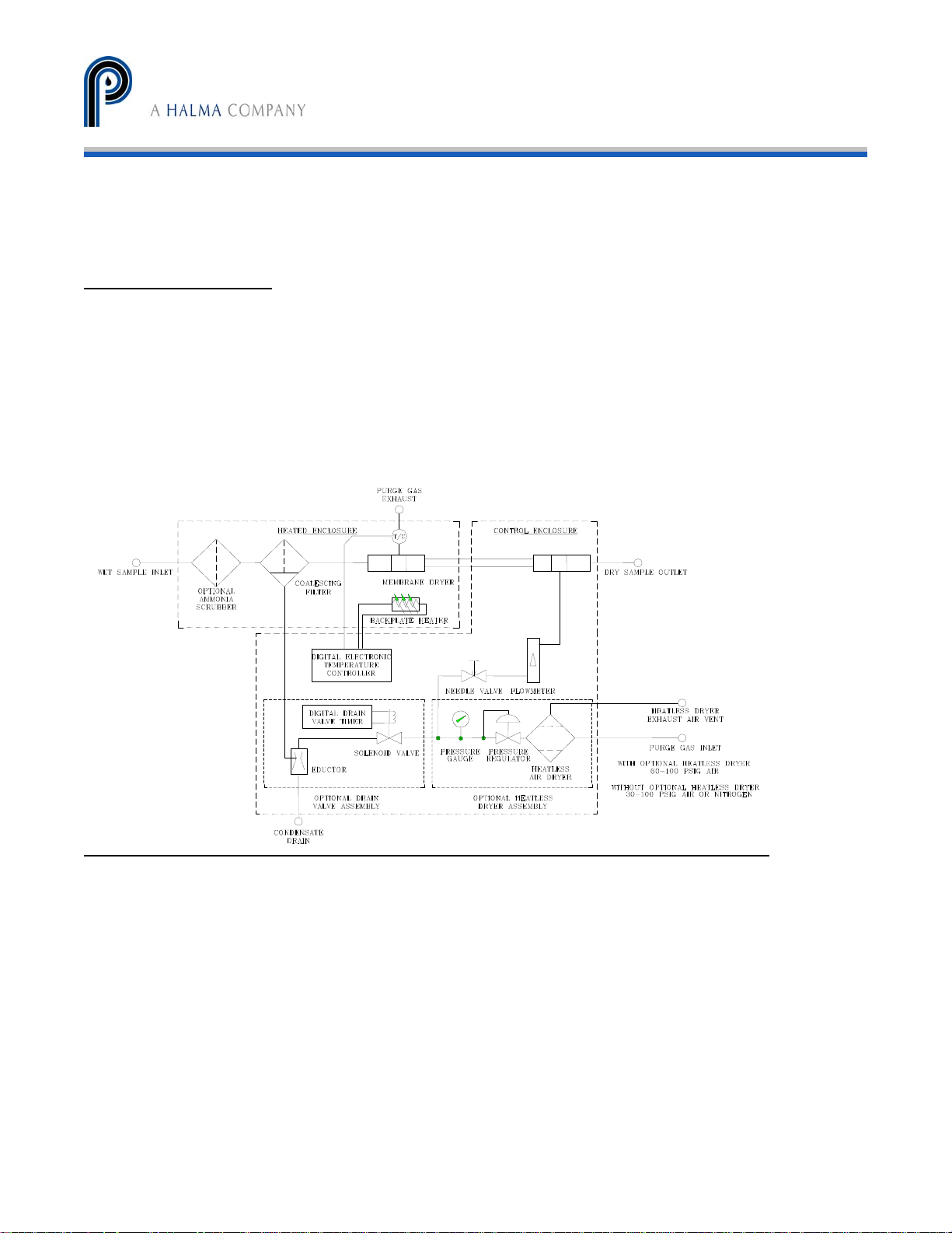
Proven tube-in-shell membrane technology is the basis of the Mini-GASS™ Conditioning System,
which selectively removes water vapor from a gas stream. The driving force is the vapor pressure
differential between the sample gas and a purge gas counter-flowing outside the tubing. This
difference quickly dries the gas stream.
The Mini-GASS standard features include a heated enclosure, particulate and/or coalescing filter,
Nafion® gas dryer, temperature controller and dryer purge flow controls. There are also a number
of options which may have been included in your system. See Figure 1
Figure 1
Mini-GASS flow diagram
6
Mini-GASS User Manual | Original Instructions
Page 7

Vortex cooler(w/sample pump) 2 CFM clean, dry air @ 80PSIG
PERMA PURE LLC
Mini-GASS™ User’s Manual
Doc. #212: Revision: 00A
Page 7 of 32
Specifications and Features
Sample flow rate 0 to 10 lpm
Sample inlet temperature 250°F (121°C) max. with stainless steel filter
230°F (110°C) max. with Kynar filter
Sample inlet water vapor 30% by volume maximum
Sample inlet pressure:
Without purge eductor option
With purge eductor option
Purge air requirements Maximum 1 cfm of oil-free instrument air or nitrogen
Outlet sample dew point
With PD-200T-24SS dryer 26° F (-4° C) at 10 lpm
With PD-100T-24SS dryer 36° F (2° C) at 10 lpm
With PD-50T-24SS dryer 42° F (5° C) at 10 lpm
Gas sample inlet and outlet fittings ¼” or 3/8” tubing fittings
Electrical requirements
Fuse 8A/4A BUSS type AGC or equivalent
Enclosure NEMA 4X, Fiberglass with polycarbonate cover
Dimensions:
MG-1228 12” W x 28” H x 7” Deep
MG-2812P 28” W x 12” H x 7” Deep
MG-1220 12” W x 20” H x 7” Deep
Operating environment -20°C to 40°C ambient temperature; 0-95% RH
maximum 20 psig;
minimum 5” H
minimum 10” H
with less than -40°C dew point
12° F (-12° C) at 5 lpm
-12° F (-25° C) at 2 lpm
26° F (-4° C) at 5 lpm
6° F (-15° C) at 2 lpm
34° F (1° C) at 5 lpm
22° F (-6° C) at 2 lpm
115V ±10% or 230V ±10%, 50/60Hz, 8.0A/4.0A (up to
900 Watts depending on options)
Altitude – up to 2000m
O vacuum
2
0 vacuum
2
Mini-GASS User Manual | Original Instructions
7
Page 8
PERMA PURE LLC
Mini-GASS™ User’s Manual
Doc. #212: Revision: 00A
Page 8 of 32
Installation
Mounting
1. Install Mini-GASS system on vertical surface with dryer/filter compartment on top and
control compartment on bottom.
2. Place mounting feet on each corner of enclosure with slotted end protruding at a 45° angle.
3. Drop mounting screw in from top and tighten into foot.
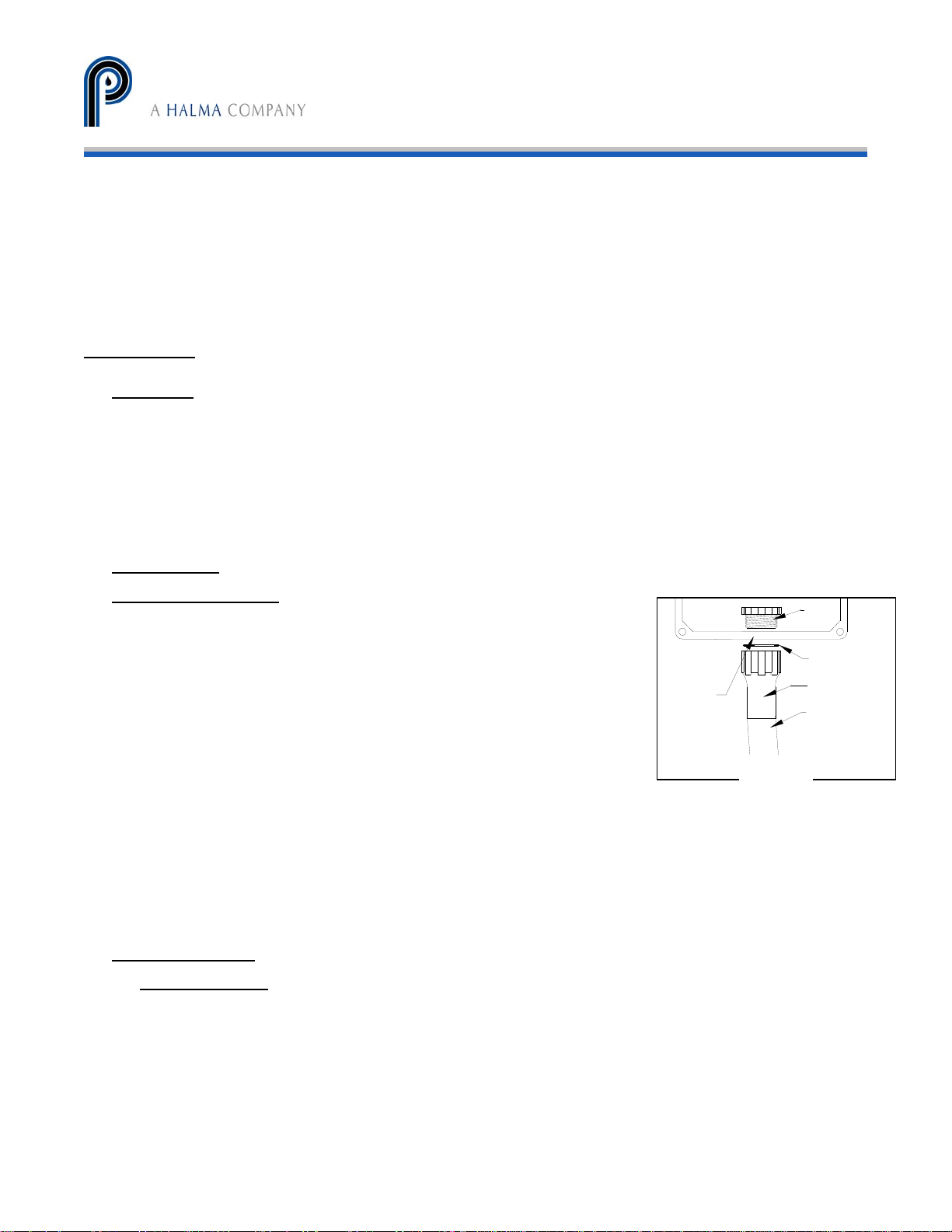
Connections (Refer to figure 2)
Heated sample line
1. Install heated line sealing fitting by threading hub into sleeve.
2. Ensure o-ring seal is installed on outside of enclosure (between
sleeve & enclosure wall).
3. Run heated sample line through entry seal and into enclosure.
4. Connect sample line to compression fitting (labeled “Wet
Sample In”)
5. Shrink entry seal tubing around heated sample line with heat gun.
6. Connect sample outlet port of Mini-GASS to sample line running to analyzers. High
temperature heated line is not necessary for this connection. If sample line will be exposed
to freezing temperatures, freeze protected line is recommended.
ENCLOSURE
Figure 2
HUB
FITTING
SEAL
O-RING
SLEEVE
FITTING
LINE
HEATED SAMPLE
Purge air supply
Instrument air
Purge gas must be of instrument grade with dew point no higher than -40°C.
1. On model MG-1214, the purge gas should be supplied to dryer via a 0-30 slpm
flow meter and a regulator capable of supplying 0-50 psig. All other models come
with a control panel that includes a flow meter and regulator.
2. For all other models, connect a 30-100 psig purge gas supply line to the ¼”
female NPT purge inlet port of membrane dryer labeled “Instrument Air”.
8
Mini-GASS User Manual | Original Instructions
Page 9
PERMA PURE LLC
Mini-GASS™ User’s Manual
Doc. #212: Revision: 00A
Page 9 of 32
Heatless air dryer (optional)
1. Connect oil-free compressed air line to port labeled “Purge Gas Inlet”
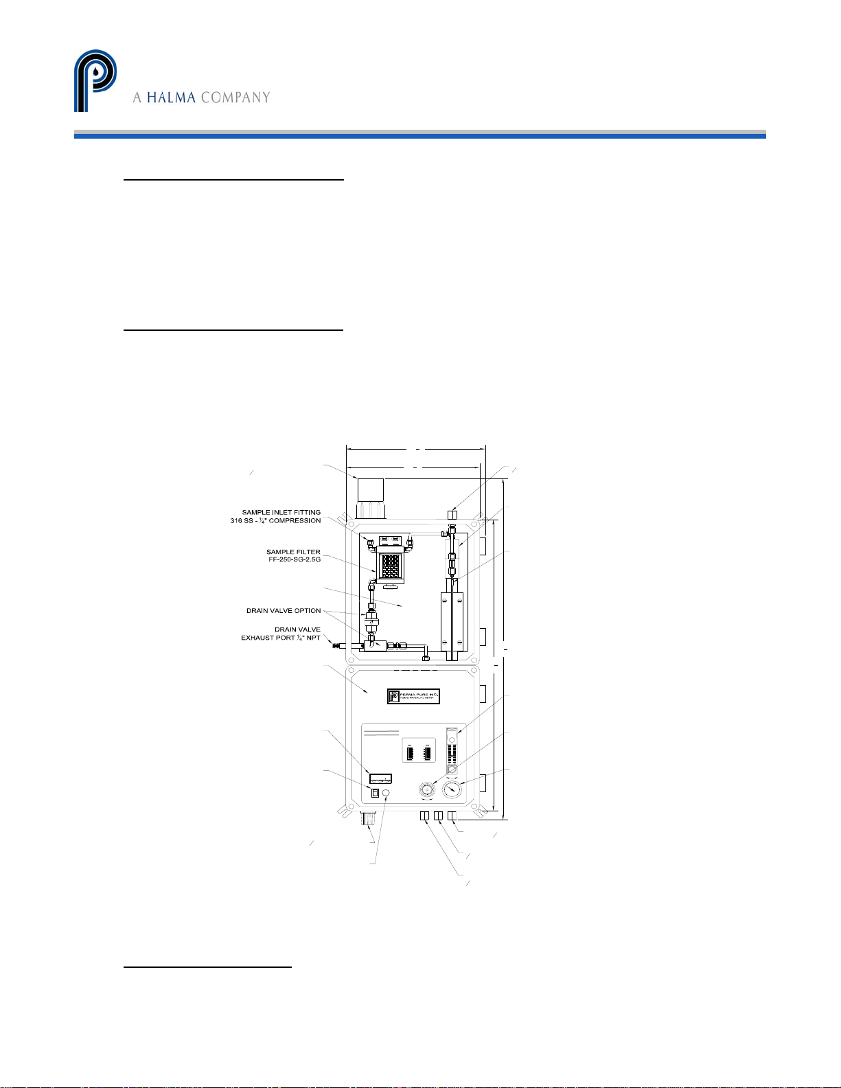
2. A ¼” FNPT bulkhead fitting on bottom of enclosure is the heatless dryer purge air
exhaust, see figure 3. Humid air can be vented to atmosphere or piped to a
remote location.
Purge air exhaust (optional)
To vent the purge gas exhaust to a remote location, connect a line to the ¼” FNPT fitting
labeled “Purge Exhaust Port”. This is suggested for gas samples that are toxic, flammable or
otherwise hazardous. In case of failure of seal integrity, the sample will be vented to the
remote location. For runs under 10 ft, ¼” OD tubing is acceptable. For runs 10-40 ft,
3/8”
OD tubing is recommended.
5
12
"
PURGE AIR
700
*
8
1
12
"
8
TM
2
S
U
E
FUSE
F
F
TYPE AGC
E
U
S
S
5.0 A.
U
E
F
120 VAC
PURGE FLOWRATE
FILTER DRAIN
TIMER SETTINGS
COMBINE
SWITCHES IN
ON
OFF
ON POSITION
0.1
0.2
0.4
0.8
1.6
3.2
6.4
12.8
25.6
51.2
OFF
FOR TOTAL
TIME DELAY
Increase Decrease
0.25
0.5
128
ON
PRESSURE ADJ.
30
TIME DELAY
IN HOURS
25
20
1
2
4
8
15
16
32
64
10
OFF
5
IncreaseDecrease
15
10 20
psi
255
0 30
FLOWMETER
SUPPLY PRESSURE
TIME DELAY
IN MINUTES
ON
PURGE EXHAUST PORT
1
" NPT FEMALE
4
NAFION MEMBRANE
DRYER
MODEL PD-200T-24SA
PURGE EXHAUST
TEMPERATURE SENSOR
3
34
"
4
5
29
"
8
MEMBRANE DRYER
PURGE AIR FLOWMETER
FLOWMETER SUPPLY
PRESSURE REGULATOR
FLOWMETER SUPPLY
PRESSURE GAUGE
SAMPLE INLET
SEALING FITTING FOR
1
" O.D. HEATED LINE
1
2
HEATED BACKPLATE
HEATLESS DRYER OPTION
BELOW FRONT PANEL
DIGITAL ELECTRONIC
TEMPERATURE CONTROLLER
POWER SWITCH
Mini-G.A.S.S.
Gas Analysis Sampling System
EXHAUST TEMPERATURE
1
CAL 3200
ON
I
0
OFF
POWER
DRY SAMPLE OUTLET
POWER CONNECTION
1
" CONDUIT HUB
2
110/220 VAC
FUSE
1
316 SS -
" NPT FEMALE
4
PURGE AIR INLET
1
" NPT FEMALE
4
HEATLESS DRYER
PURGE AIR EXHAUST
1
" NPT FEMALE
4
Figure 3 - Mini-GASS Sampling System
Filter drain (optional)
Connect the line from the eductor outlet to designated collection/exhaust basin containing
acid absorption media to prevent release of exhaust to surrounding. ¼” i.d. tubing can be
9
Mini-GASS User Manual | Original Instructions
Page 10
PERMA PURE LLC
Mini-GASS™ User’s Manual
Doc. #212: Revision: 00A
Page 10 of 32
used for runs up to 10 feet, or larger i.d. tubing for longer exhaust lines. Line should not
restrict purge flow.
Purge eductor inlet connection (optional)
Connect air supply line to compression fitting labeled “Instrument Air”.
Steam connection (optional)
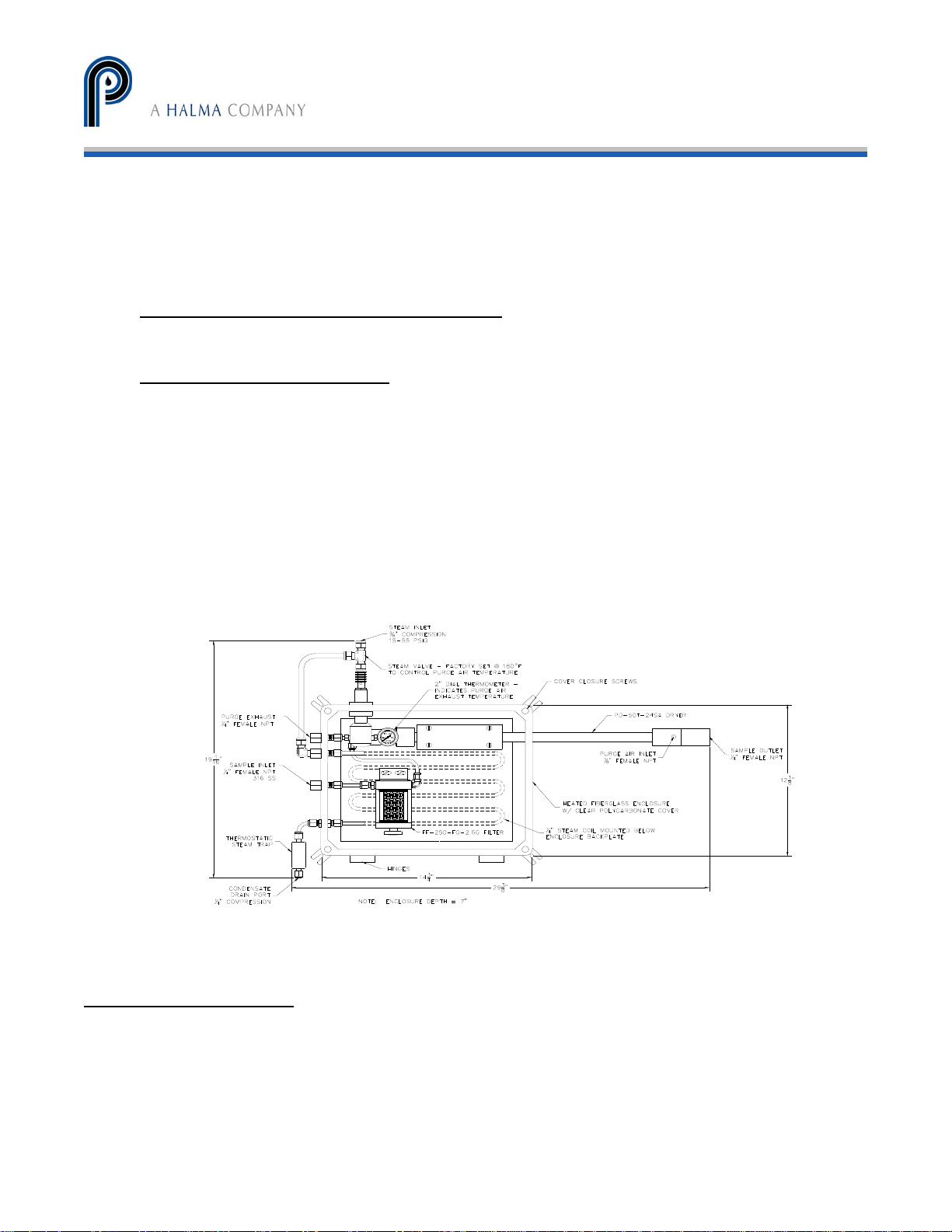
(Refer to figure 4)
1. Insulate supply line to steam control valve.
2. Insulate supply line between valve and steam coil.
3. Supply low pressure steam (50 psig max) to steam coil. Do not exceed this pressure or
overheating may occur.
Outlet end of steam coil located at lower left side of enclosure is connected to a
thermostatic steam trap to allow condensed steam to drain in a controlled manner.
Condensate can be piped to a wastewater drain or to condensate recovery system.
Figure 4 - Steam heated Mini-GASS
Electrical connections
Mini-GASS Model #1220 and 2812T (Transportable) have a power cord and plug for 115 VAC and
power cord with pigtail wires for the 230 VAC version.
For Mini-GASS model # 1228:
Mini-GASS model 1228 is intended to be hard wired via a customer supplied disconnect
switch and wire capable of supplying 5A/10A/115/230/VAC. The external disconnect switch
must meet IEC 60947-1 & 60947-3 standards and must be installed in close proximity to
Mini-GASS User Manual | Original Instructions
10
Page 11
PERMA PURE LLC
Mini-GASS™ User’s Manual
Doc. #212: Revision: 00A
Page 11 of 32
the equipment, within easy reach of the operator and shall be clearly marked as the
disconnecting device for the Mini-GASS.
Connect power supply line to terminal block located on the backplate of the control
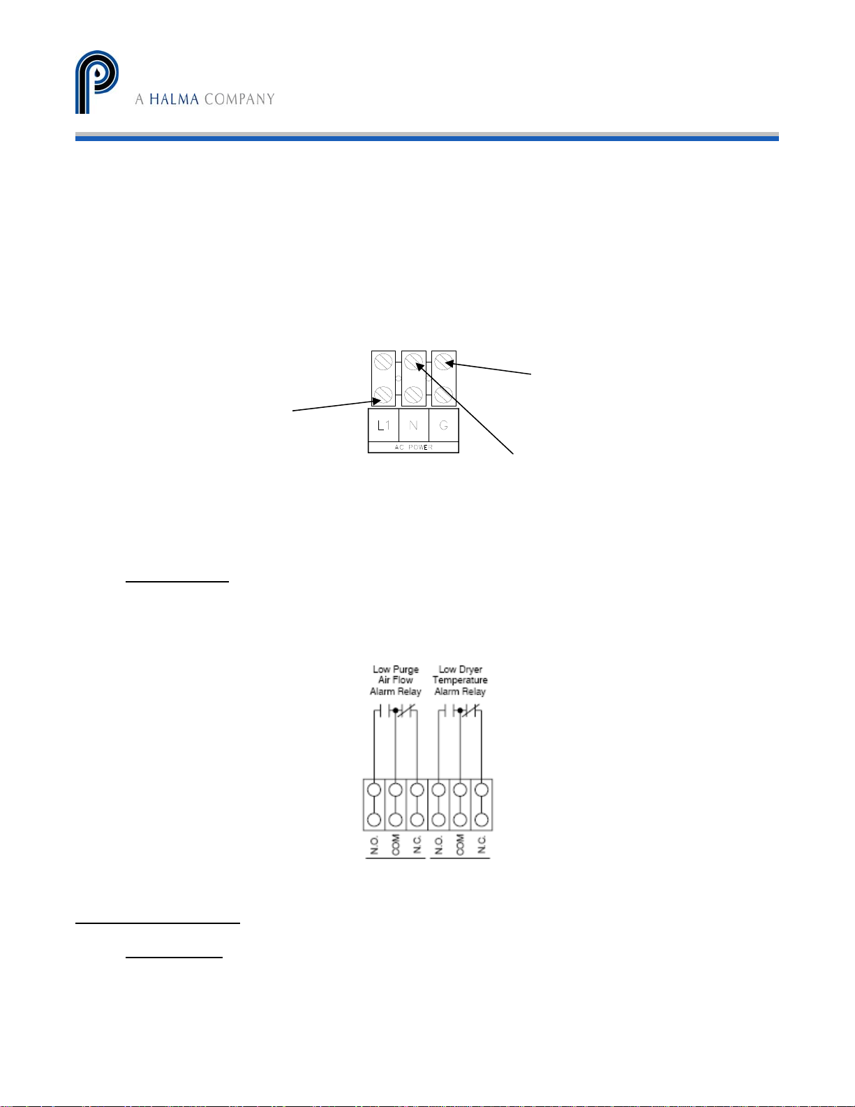
enclosure inside the ½” conduit hub. (Refer to figure 5 for color coding). Connect the
system to an appropriate earth ground. Adhere to all electrical code requirements in effect
at the installation site. Connect power such that the protective earth conductor is the last to
take the strain.
Green/yellow – Connect ground earth
here
Brown – Connect Line L1 here
Blue – Connect neutral or Line L2 here
Figure 5 – Electrical Connections
Alarm Relays
The SIVS2 has a 6 pole terminal block that will allow for field wiring of alarm relays for
connection of external alarm equipment (refer to Figure 6). Relay contacts are rated at 250
VAC, 3A, resistive. See Appendix F for additional information.
Figure 6 – Alarm Relays
Start-up procedure
Setup Check
1. Check that electrical, sample purge drain and /or steam connections have been
made.
2. Turn on compressed or instrument air to system.
11
Mini-GASS User Manual | Original Instructions
Page 12
PERMA PURE LLC
Mini-GASS™ User’s Manual
Doc. #212: Revision: 00A
Page 12 of 32
Automatic Filter Drain Control
(Optional)
Automatic filter drain is controlled by a repeat cycle timer that operates a solenoid valve.
Two DIP switches are located on timing device to control drain and cycle times located on
backside of control panel.
Standard factory setting is to drain for 0.1 minute once every 24 hours.
0.1 minutes (1
Drain Time (left DIP switch)
102.3 minutes (all switches on)
1 hour (1
Cycle Time (right DIP switch)
1023 hours (all switches on)
1. Adjust purge air pressure regulator to about 15 psig.
Sample under vacuum: Purge air regulator will control air pressure to educator of
the automatic filter drain. Regulator must be set to provide ample vacuum to
remove filter condensate but not excessive enough to cause interruption in sample
flow to analyzers.
Under positive pressure: Condensate drain flow is directly controlled by solenoid
valve. When solenoid valve is actuated (opened), positive pressure in filter housing
purges condensate out of system through drain line.
2. Initially adjust DIP switches on drain timer to drain for 6 seconds every 24 hours. Time
on switches is additive. Left switch should have only top 0.1 min. switch in the “ON”
position and right switch should have 8 and 16 hr. switches in the “ON” position. Time
periods may need further adjustments after system has been in operation.
st
switch on – all others off)
To
st
switch on – all others off)
To
Temperature Control
PID Electronic Temperature Controller
1. Press and hold “
2. Press either up or down key to adjust setpoint. Setpoint temperature will change one °C
with each press of arrow key.
3. When desired temperature is reached, release both keys.
NOTE: MG-1228, 2812P, and 1235 systems have a low temperature alarm that is
programmed into controller. Default temperature setting for alarm is 5° C below
setpoint temperature. Refer to CAL Controls temperature controller manual for more
information.
” key on the CAL Controls temperature controller.
12
Mini-GASS User Manual | Original Instructions
Page 13

PERMA PURE LLC
Mini-GASS™ User’s Manual
Doc. #212: Revision: 00A
Page 13 of 32
Steam Temperature Control
Steam heated systems are regulated by a thermostatic steam control valve located in the
purge air exhaust stream. This valve is preset at the factory to an appropriate temperature
determined by sample conditions. A typical setpoint temperature is 180° F which is the
approximate temperature of the purge air exhaust indicated by analog thermometer located
in the purge air exhaust stream.
Safety Interlocks
Systems equipped with the SIVS2 interlock option automatically shuts off the sample pump
in the event of low purge airflow or low temperature in the system. To accomplish this, a
differential pressure switch in the purge air inlet senses the flow of purge air and energizes
a relay. This relay then sends power to the contacts of a second relay which will energize
only when temperature set point has been reached. Under normal operating conditions both
safety relays will remain energized (When the system is operating normally, open contacts
will close and remain closed). Alarm relays may be field wired to initiate an external alarm.
See Appendix F for additional information.
Preheating the system
1. Turn on AC power or steam to system.
WARNING!
On AC powered units, temperature control display should light. DO NOT BEGIN SAMPLE
FLOW AT THIS TIME! Check purge air is flowing immediately after turning on AC power or
steam. If, for any reason, there is no purge air or flow is inadequate, turn off AC power or
steam before attempting to locate problem. OPERATING SYSTEM WITH LITTLE OR NO
PURGE AIR CAN CAUSE DAMAGE TO MEMBRANE DRYER ASSEMBLY.
2. Set purge air pressure to 15 psig.
3. Adjust purge air flow to 20 L/min.
4. Set purge air educator vacuum level to 5 in-Hg (if applicable).
5. Ensure purge air is exhausting from system.
6. The temperature controller will be alternately displaying –AL– and actual purge air
exhaust temperature until purge air temperature comes within 5° C of setpoint
temperature.
7. Allow 15 – 30 minutes of additional heating time after system has come to setpoint
temperature. Sample flow may be started. For Mini-GASS with a pump, when set on
“AUTO” mode, pump will turn on when unit has reached temperature and purge gas is
sensed.
Mini-GASS User Manual | Original Instructions
13
Page 14

PERMA PURE LLC
Mini-GASS™ User’s Manual
Doc. #212: Revision: 00A
Page 14 of 32
System fine tuning
Temperature adjustment
Steam heated systems
Steam control valve is factory set to 180° F and is normally not field adjustable.
This temperature is adequate for most applications in which sample gas water
content is not in excess of 50% water vapor by volume. Consult factory if
condensation in sample tubing is detected.
Electrically heated systems
1. Check that no condensate is present in sample line between filter and dryer.
2. If water droplets are visible, increase temperature of filter/dryer compartment by
5° C.
3. Allow about ½ hour for system to stabilize and then check again for condensate.
4. If necessary, continue to increase temperature in 5° C increments until
condensate is no longer visible. Do not exceed 100° C! Maximum system
temperature is 100° C. Operation above this temperature can cause damage to
Nafion dryer. It is essential that purge gas flows continuously and
setpoint temperature is not above 100° C to prevent damage to dryer.
Maintenance
Filters
If system is fitted with a pre-filter, it should be checked regularly to ensure that the element
is in good condition. If element appears to be dirty or begins to cause flow restriction in
system, it should be replaced.
Filter Element Replacement
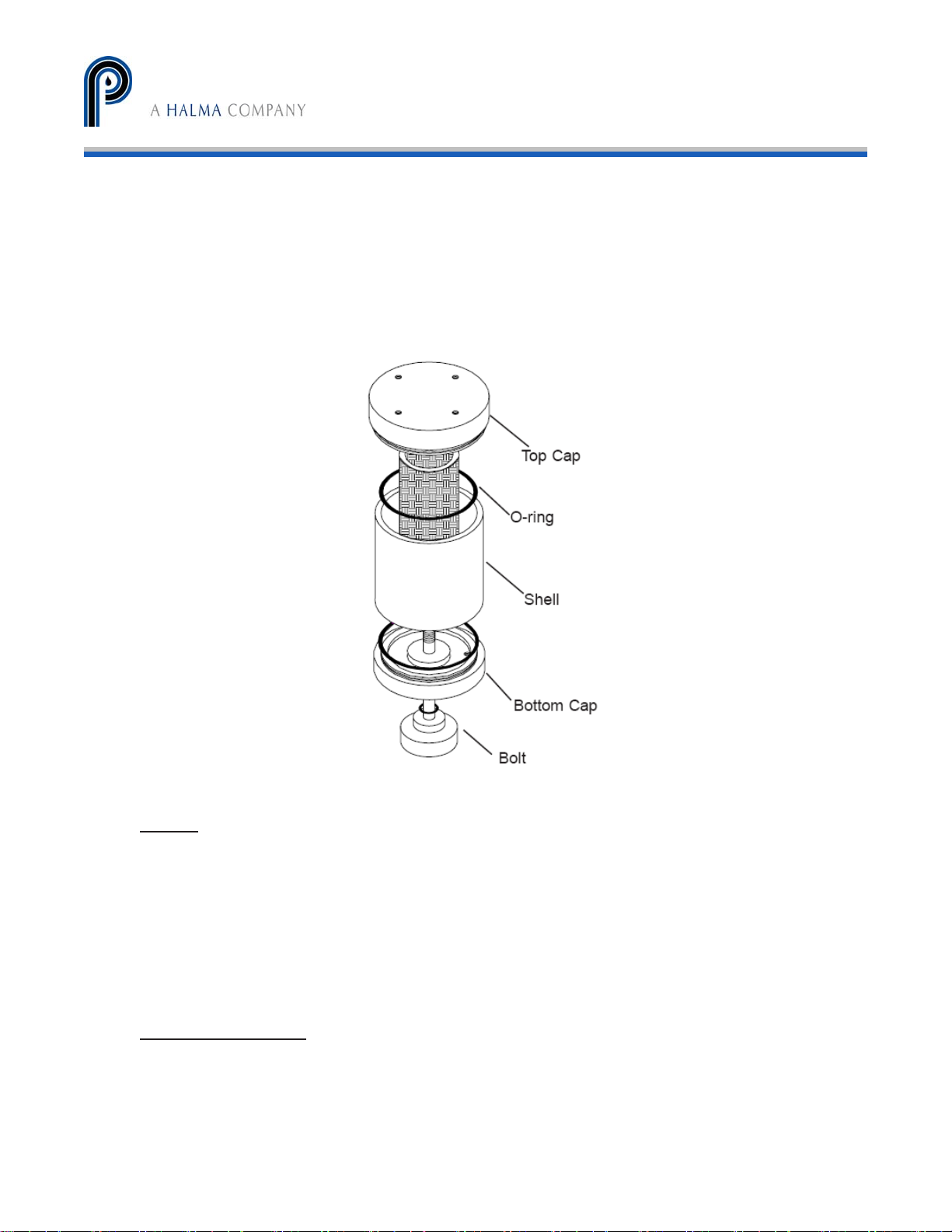
(Refer to Figure 7)
1. Loosen bolt on bottom of filter.
2. Gently pull apart assembly and remove old element.
3. Place new element into grooves in top and bottom of housing.
4. When re-assembling, inspect for o-rings on top and bottom caps and on center bolt.
5. Install glass shell onto bottom piece.
14
Mini-GASS User Manual | Original Instructions
Page 15
PERMA PURE LLC
Mini-GASS™ User’s Manual
Doc. #212: Revision: 00A
Page 15 of 32
6. Place new element in groove in bottom piece. Be sure that element is seated correctly
and parallel to glass shell.
7. Carefully mate bottom assembly onto top piece. Slight twisting motion may be required
to allow shell to slip over o-ring seal.
8. Visually make sure element is seated correctly in top groove.
9. Replace bolt through hole in bottom piece and screw clockwise into top piece. Do not
over-tighten center bolt. It should be just tight enough so it does not vibrate loose.
Over-tightening will not help the filter to seal.
Figure 7 – Filter Element Replacement
Dryers
Under normal conditions, Perma Pure dryers require little maintenance and can last for
several years. However, if there is no pre-filter and the tubing becomes clogged or
saturated with water, the dryer may require cleaning or repair. When disassembling the
dryer, note that the end fittings on the PD-SERIES dryer can be easily rotated on the shell
tube. This rotation should be avoided to prevent twisting the membrane tubes inside the
shell.
Refer to Appendix B for PD dryer element replacement.
Ammonia Scrubber
Media Replacement: When deposits are visible on 75% of the scrubber, scrubbing media
needs to be replaced.
1. Unscrew thumbscrew on bottom of housing.
2. Swing yoke to one side.
Mini-GASS User Manual | Original Instructions
15
Page 16

PERMA PURE LLC
Mini-GASS™ User’s Manual
Doc. #212: Revision: 00A
Page 16 of 32
3. Separate housing and bottom cap as an assembly from top cap.
4. Remove spring and top screen.
5. Remove old media and dispose of properly (rinse housing with soapy water to clean).
6. Fill housing with 50cc of Berl Saddles (tap housing to allow material to settle).
7. Pour 150cc of Scrubbing Media (tap housing to allow material to settle).
8. Replace stainless steel screen on top of media.
9. Replace spring on top of screen.
10. Clean o-rings on shell and inside top manifold (replace if necessary).
11. Place center tube into o-ring seal in top cap.
12. Push and twist to seal housing around o-ring.
13. Replace yoke and finger tighten thumbscrew (do not over tighten).
Fuse
Fuse Replacement
1. Turn cap marked “FUSE” counter-clockwise ¼ turn and the fuse holder will come out.
2. Remove the blown fuse and replace with one of equal amperage rating. The standard
fuse is a BUSS type AGC or equivalent.
3. After installing correct replacement fuse, re-install fuse holder by pressing inward and
twisting ¼ turn clockwise.
Mini-GASS User Manual | Original Instructions
16
Page 17

PERMA PURE LLC
Mini-GASS™ User’s Manual
Doc. #212: Revision: 00A
Page 17 of 32
Replacement parts
3RPA-001 Replacement instrument air regulator
MG-DTC Digital temperature controller, single channel
MG-TCS J-Type thermocouple
MG-SSR Solid state relay
MG-FM Flow meter, purge gas (0-60 lpm)
MG-PR Pressure regulator, purge gas or educator
MG-DPS Differential pressure switch for purge flow detection
MG-PG-0-30 Pressure gage, purge gas (0-30 psi)
MG-VG-0-60 Vacuum gage, purge educator (0-30”Hg)
FF-DCV Drain check valve, polypropylene, for vacuum drain
DVV-B10 Drain solenoid valve, brass, for vacuum drain 110V/60Hz
DVV-B20 Drain solenoid valve, brass, for vacuum drain 220V/50Hz
DVP-K10 Drain solenoid valve, kynar, for pressure drain 110V/60Hz
DVP-K20 Drain solenoid valve, kynar, for pressure drain 220V/50Hz
MG-DVT Drain valve timer
MG-DC Mounting clamps for dryer (specify dryer model)
MG-1412-HB Backplate with heater for enclosure 1412
PD-50T-24EM 50 tube dryer replacement element, 24” long, includes O rings
PD-100T-24EM 100 tube dryer replacement element, 24” long, includes O
rings
PD-200T-24EM 200 tube dryer replacement element, 24” long, includes O
rings
FF-250-E-2.5G Replacement filter element
FF-350G Replacement glass shell for filter
FF-250-3 Replacement O ring set, set of 3 rings
AS-200-08-EB Media replacement for ammonia scrubber, bulk supply, 5
Mini-GASS User Manual | Original Instructions
17
Page 18

PERMA PURE LLC
Mini-GASS™ User’s Manual
Doc. #212: Revision: 00A
Page 18 of 32
fillings
MG-PUMPKIT Pump repair kit, Teflon diaphragm
SP-270E Ceramic filter element for MG-1228P
Mini-GASS User Manual | Original Instructions
18
Page 19

PERMA PURE LLC
Mini-GASS™ User’s Manual
Doc. #212: Revision: 00A
Page 19 of 32
APPENDIX A: Warranty and disclaimers
Perma Pure LLC
Perma Pure (Seller) warrants that product supplied hereunder shall, at the time of delivery to
Buyer, conform to the published specifications of Seller and be free from defects in material and
workmanship under normal use and service. Seller’s sole obligation and liability under this
warranty is limited to the repair or replacement at its factory, at Seller’s option, of any such
product which proves defective within one year after the date of original shipment from seller’s
factory (or for a normal usable lifetime if the product is a disposable or expendable item) and is
found to be defective in material or workmanship by Seller’s inspection.
Buyer agrees that (1) any technical advice, information, suggestions, or recommendations given to
Buyer by Seller or any representative of Seller with respect to the product or the suitability or
desirability of the product for an particular use or application are based solely on the general
knowledge of Seller, are intended for information guidance only, and do not constitute any
representation or warranty by Seller that the product shall in fact be suitable or desirable for any
particular use or application; (2) Buyer takes sole responsibility for the use and applications to
which the product is put and Buyer shall conduct all testing and analysis necessary to validate the
use and application to which Buyer puts the product for which Buyer may recommend the use or
application of the product by others; and (3) the characteristics, specifications, and/or properties
of the product may be affected by the processing, treatment, handling, and/or manufacturing of
the product by Buyer or others and Seller takes no responsibility for he nature or consequence of
such operations or as to the suitability of the product for the purposes intended to be used by
Buyer or others after being subjected to such operations.
SELLER MAKES NO OTHER WARRANTY, EXPRESS OR IMPLIED, OF THE PRODUCT SUPPLIED HEREUNDER,
INCLUDING, WITHOUT LIMITATION, IMPLIED WARRAN TI ES OF MERCHANTABILITY AND FITNESS FOR
PARTICULAR PURPOSE, AND ALL SUCH WARRANTIES ARE HEREBY EXPRESSLY EXCLUDED. SELLER
SHALL HAVE NO LIABILITY FOR LOSS OF PROFITS, OR SPECIAL, INCIDENTAL, OR CONSEQUENTIAL
DAMAGES UNDER ANY CIRCUMSTANCES OR LEGAL THEORY, WHETHER BASED ON NEGLIGENCE,
BREACH OF WARRANTY, STRICT LIABILITY, TORT, CONTRACT, OR OTHERWISE. SELLER SHALL IN NO
EVENT BE LIABLE IN RESPECT OF THIS ORDER AND OR PRODUCT DELIVERED ON ACCOUNT OF THIS
ORDER FOR ANY AMOUNT GREATER THAN THAT PAID TO SELLER ON ACCOUNT OF THIS ORDER.
Mini-GASS User Manual | Original Instructions
19
Page 20
PERMA PURE LLC
Mini-GASS™ User’s Manual
Doc. #212: Revision: 00A
Page 20 of 32
APPENDIX B: Dryer element replacement
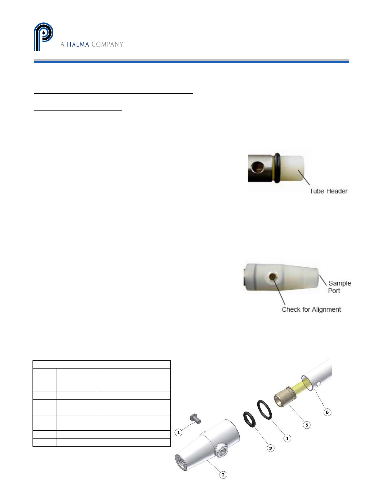
TO DISASSEMBLE DRYER
Tools Needed:
- Phillips head screwdriver
- unsharpened pencil with eraser
1. Loosen locking screws on both ends of dryer.
2. Insert eraser end of pencil into one sample port
until it rests on tube header face (Refer to Figure 8).
3. Hold dryer vertically and place other end of pencil
down onto a hard, slip resistant surface.
4. While supporting shell tube, push lower end fitting down
with consistent pressure until it slips off shell tube.
Do not attempt to pull fitting from shell tube; doing this
is likely to damage dryer element tubing.
5. Repeat steps 2-4 for other end.
6. Remove one o-ring from tube header.
7. Pull tube element from opposite end of dryer.
TO ASSEMBLE DRYER (Refer to Figure 10)
Tool Needed:
- Phillips head screwdriver
1. Install one thick o-ring onto grooved tube header.
2. Slip opposite tube header into dryer shell.
Check for Alignment.
3. Install other thick o-ring onto groove.
4. Push one thin o-ring into groove inside coupling
(for SS and AL shells slip o-ring on shell
across two holes).
5. Firmly push coupling over tube header.
6. Align purge port with hole in shell tube (Refer to Figure 9).
7. Tighten locking screws until underside of screw head contacts top of boss.
8. Repeat steps 4-7 for opposite end.
PARTS LIST
ITEM QUANTITY DESCRIPTION
1 2 SCREW, 10-24 x
3/8” SS
2 2 COUPLING
3 2 ELEMENT HEADER
SEAL, VITON
4 2 SHELL TUBE SEAL,
VITON
5 1 DRYER ELEMENT
6 1 SHELL TUBE
Figure 8
Figure 9
Mini-GASS User Manual | Original Instructions
20
Page 21
PERMA PURE LLC
Mini-GASS™ User’s Manual
Doc. #212: Revision: 00A
Page 21 of 32
Figure 10
APPENDIX C: Flange Mounted with Integral Sampling Probe and Filter Blowback
Installation
Flange mounted Mini-GASS® is designed to be stack mounted on 2", 3" or 4" pipe flange. The
integral sample probe and filter eliminates need for a heated umbilical line to connect stack gas
sampling probe to sample conditioning system.
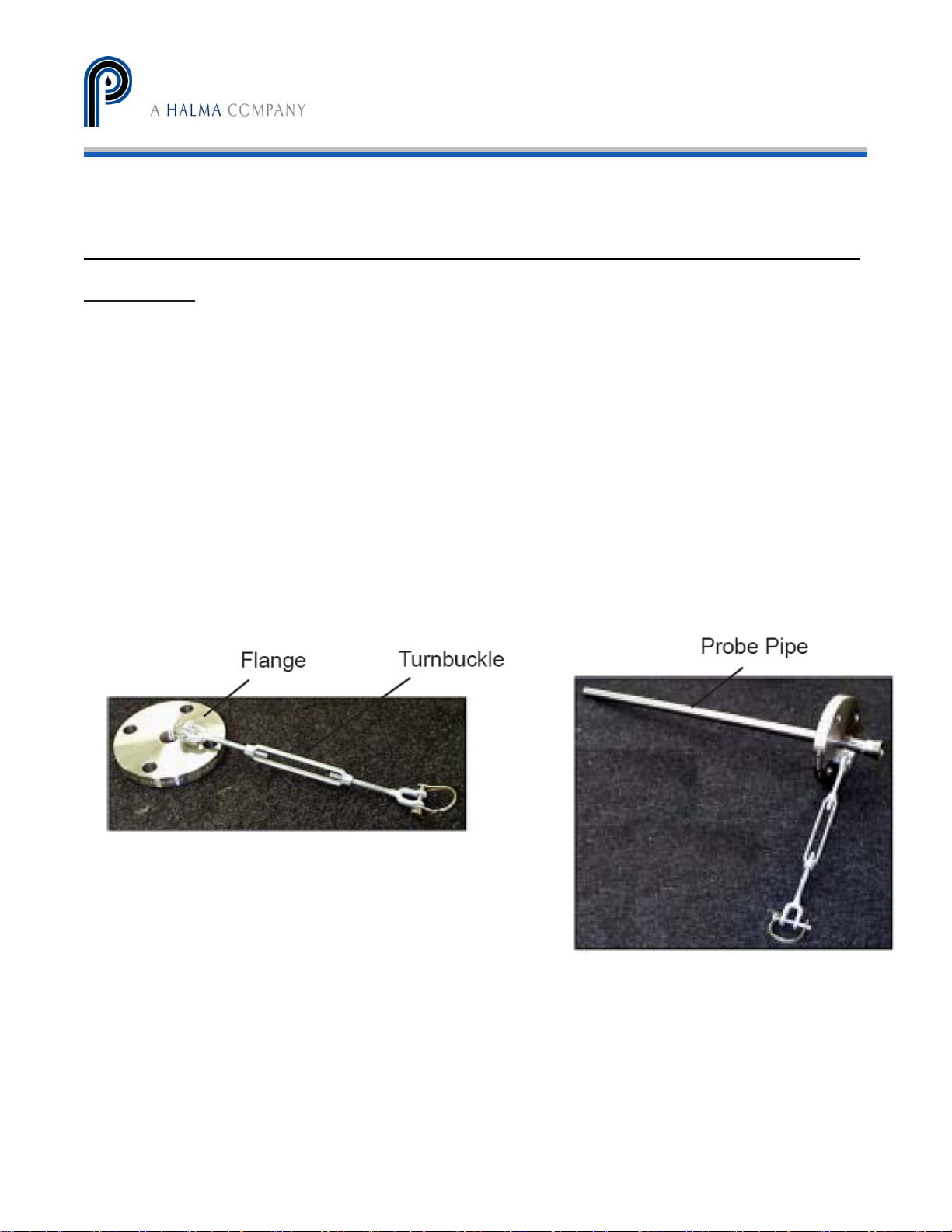
The Mini-GASS system is attached directly to sample port flange by following the steps below:
1. Attach flange to sampling port using appropriate sized gasket and bolts.
2. Align flange holes with turnbuckle anchor at bottom. Install four appropriate sized bolts
and hand tighten all four bolts evenly. Tighten with wrench (see Figure 11).
3. Install sampling probe pipe into pipe flange by inserting non-threaded end of probe pipe
through flange (see Figure 12). Probe should extend into the center of the stack and
pointing slightly downward to allow any entrained liquid to drain back into the stack.
4. Tighten probe pipe into flange with wrench. pipe
5. Attach one end of turnbuckle to anchor at bottom of flange and fix pin in place with cotter
pin.
Figure 11
Figure 12
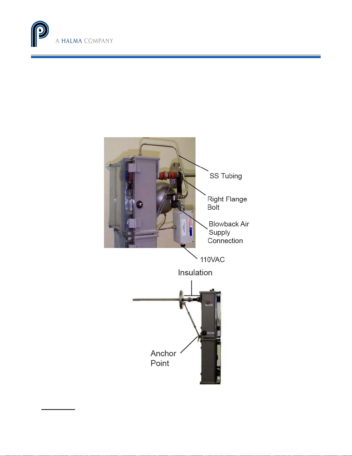
6. If system is being installed with automatic filter blow back option, install blow back
system on right flange bolt (refer to Figures 13 and 19).
7. Attach pre-bent SS tubing to Mini-GASS and to blowback assembly.
8. Lift Mini-GASS system into place so union fitting on back of system can be attached to
probe pipe. This is most easily accomplished with help of an assistant.
9. While holding system in place, tighten union hand tight.
21
Mini-GASS User Manual | Original Instructions
Page 22
PERMA PURE LLC
Mini-GASS™ User’s Manual
Doc. #212: Revision: 00A
Page 22 of 32
10. Connect free end of turnbuckle to anchor point at middle back of system (refer to Figure
14).
11. Attach with stainless clevis pin.
12. Snap keeper wire into place.
13. Adjust turnbuckle by turning it out to increase length until union fitting is
straight.
Turnbuckle is used only to relieve torsional load from union fitting.
14. Tighten union fitting with a wrench.
15. Install insulation between flange and back of Mini-GASS.
Figure 13
Figure 14
Plumbing
1. Connect blowback air line to blow back inlet port on the Mini-GASS.
22
Mini-GASS User Manual | Original Instructions
Page 23

PERMA PURE LLC
Mini-GASS™ User’s Manual
Doc. #212: Revision: 00A
Page 23 of 32
2. Connect cal gas line to fitting labeled “Cal Gas Inlet”.
3. Connect 110VAC power to blow back timer Note: This also provides power to the
filter in the probe.
Blow Back Operation
The blow back option includes a timer circuit which will initiate the blow back cycle based
on a regular, adjustable time period. The time cycle control turned to the far left will cycle the
blow back every 15 minutes. At the far right side, the period of time between cycles is about
24 hours. The period of time between blow back cycles should be calculated to occur as
often as when the filter has trapped one gram of particulates but no less frequently than
once per day.
A jumper placed between “AUTO OFF “and “COM” will disarm the timer. A contact
closure between terminals labeled “MAN B-B” and “COM” will initiate a blow back cycle.
The blow back solenoid valve will be opened for 2 seconds when the blow back cycle is
started.
Maintenance
Changing the Filter in Blow Back/Probe Assembly
1. Unscrew black filter cap inside Mini-GASS system (use gloves if hot to touch).
2. Filter is now exposed. With a pair of pliers, pull out the old filter.
3. Inspect o-rings which are at each end of filter. Replace if they are charred or deformed.
4. Place new filter element using pliers. Ensure it is centered and in contact with o-ring.
5. Screw cap back on the filter body.
23
Mini-GASS User Manual | Original Instructions
Page 24
PERMA PURE LLC
Mini-GASS™ User’s Manual
Doc. #212: Revision: 00A
Page 24 of 32
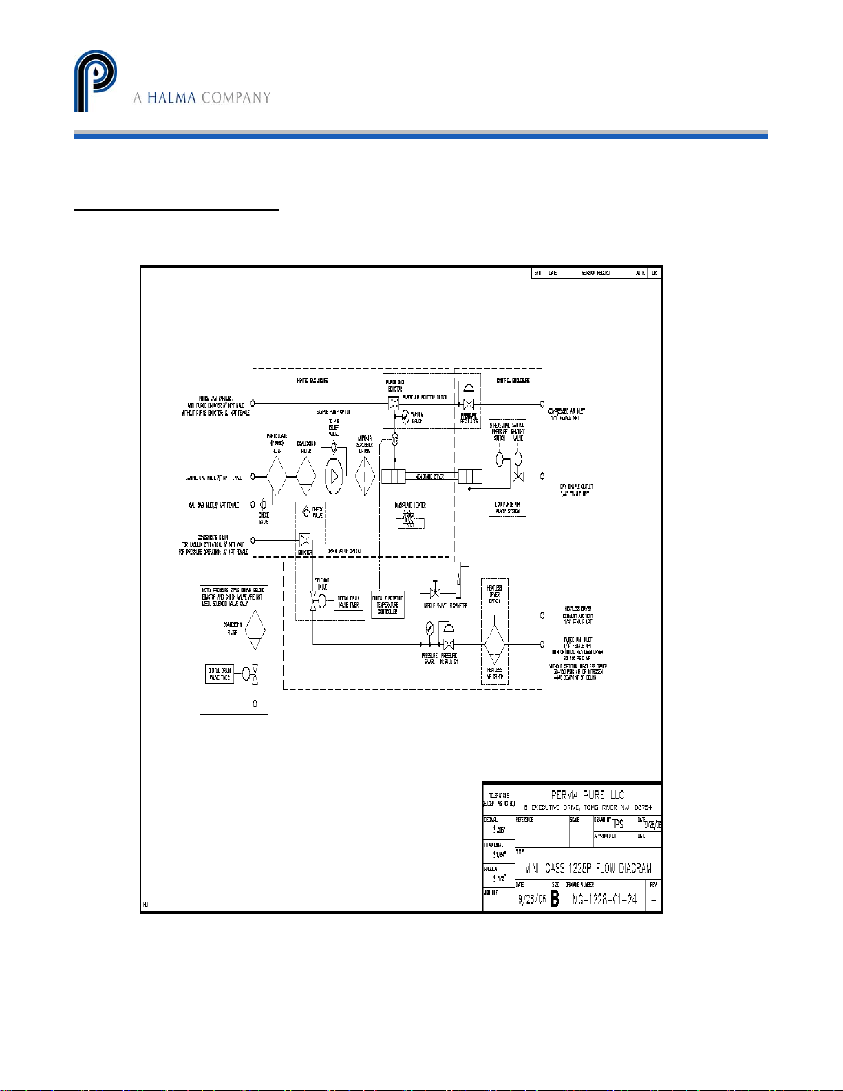
APPENDIX D: Diagrams
Mini-GASS User Manual | Original Instructions
24
Page 25
PERMA PURE LLC
Piping and Instrumentation Diagram
Mini-GASS™ User’s Manual
Doc. #212: Revision: 00A
Page 25 of 32
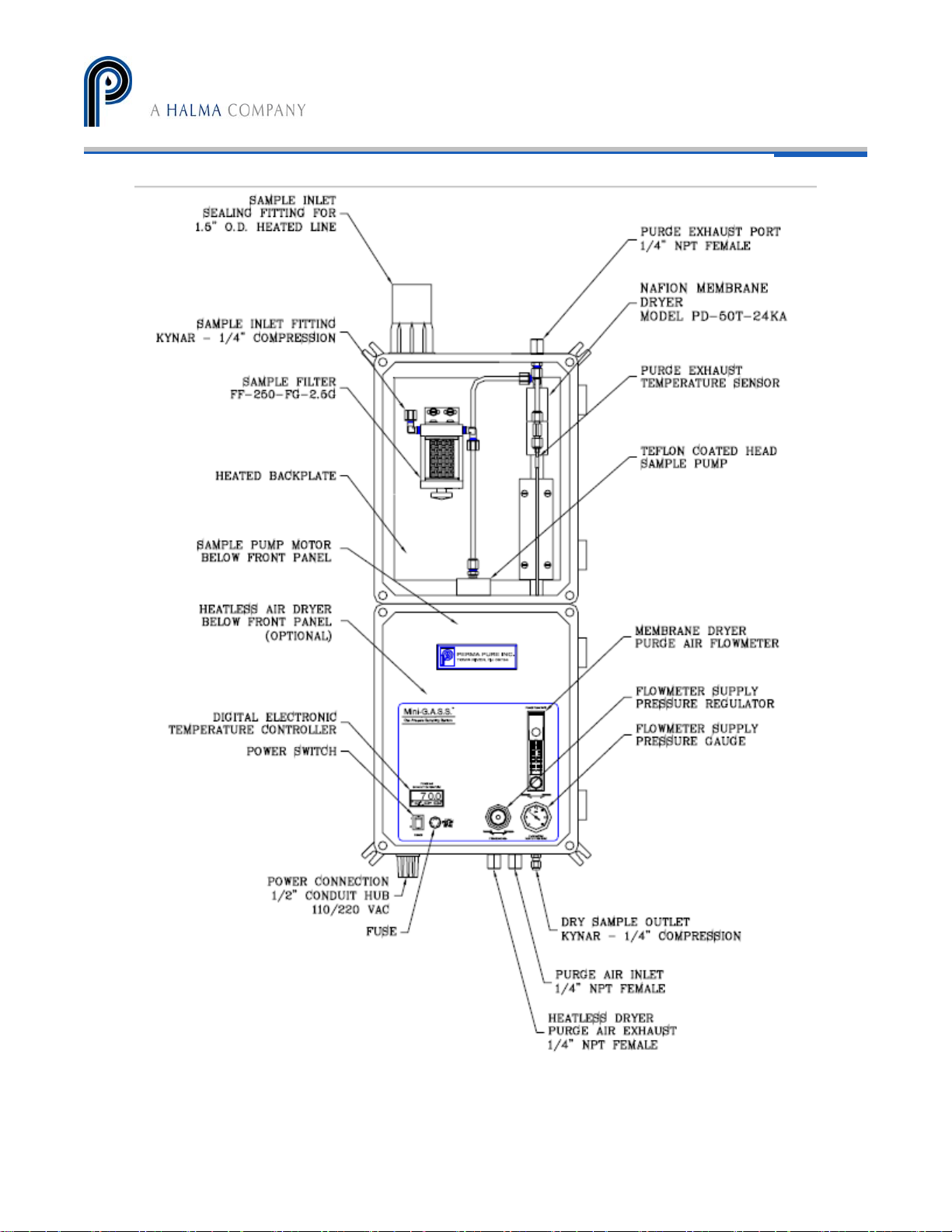
Figure 15
MG-1228 Style System
Mini-GASS User Manual | Original Instructions
25
Page 26
PERMA PURE LLC
Mini-GASS™ User’s Manual
Doc. #212: Revision: 00A
Page 26 of 32
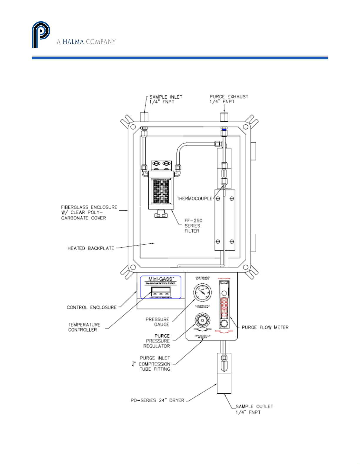
Figure 16
Mini-GASS User Manual | Original Instructions
26
Page 27
PERMA PURE LLC
Mini-GASS™ User’s Manual
Doc. #212: Revision: 00A
Page 27 of 32
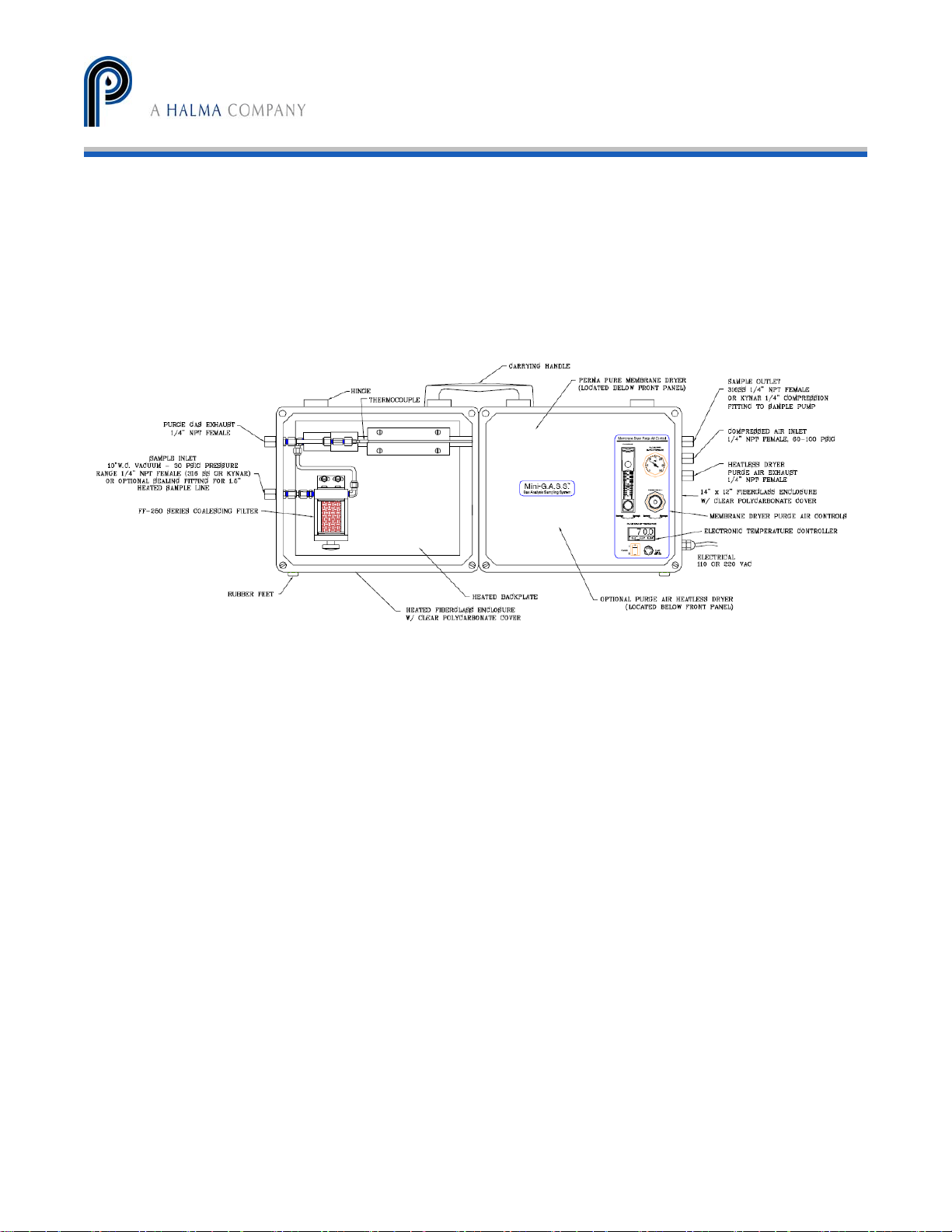
MG-1220 Style System
Figure 17 MG-2812T Transportable System
27
Mini-GASS User Manual | Original Instructions
Page 28
PERMA PURE LLC
Mini-GASS™ User’s Manual
Doc. #212: Revision: 00A
Page 28 of 32
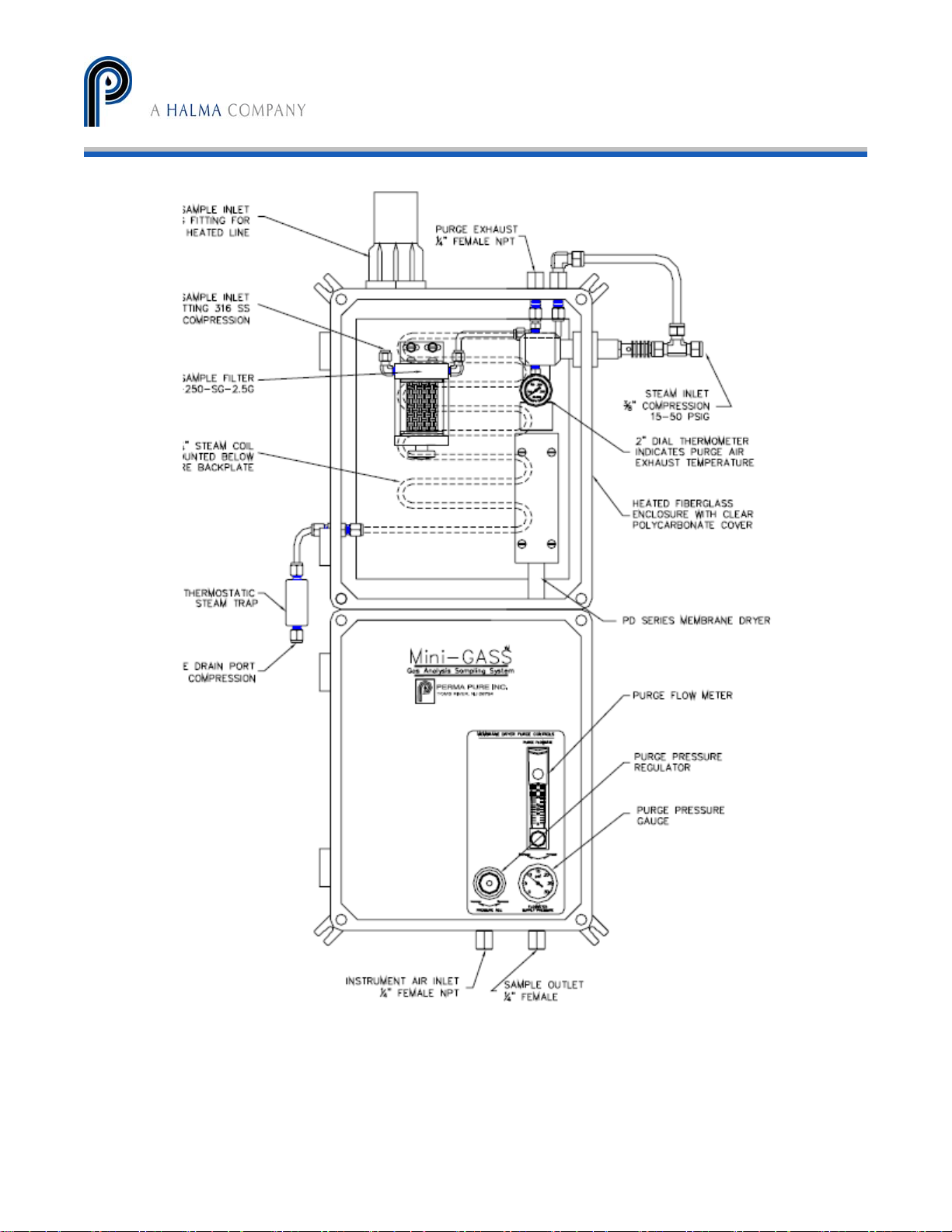
Figure 18 MG 1228 Steam System
Mini-GASS User Manual | Original Instructions
28
Page 29
PERMA PURE LLC
Mini-GASS™ User’s Manual
Doc. #212: Revision: 00A
Page 29 of 32
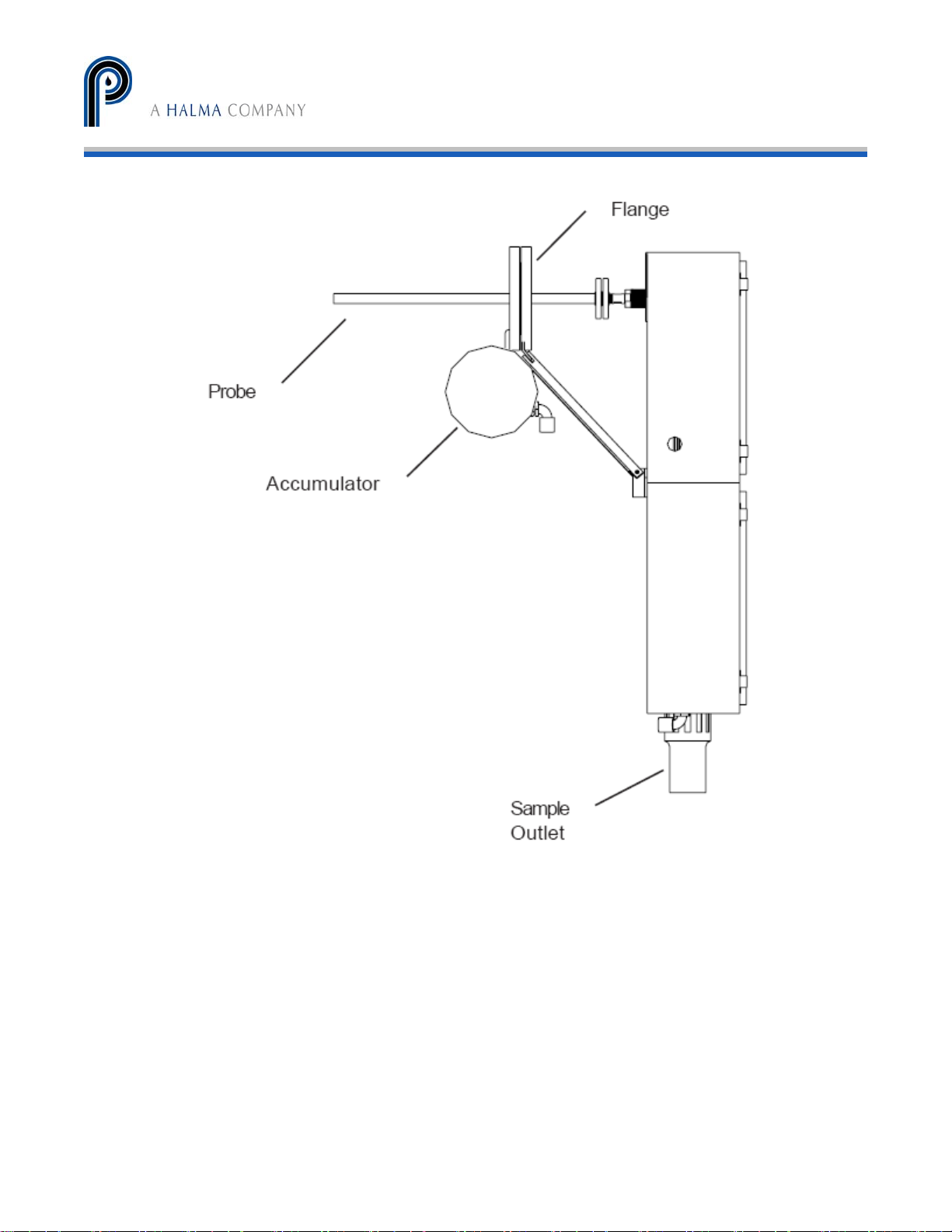
Figure 19
MG-1228 with Probe and Blowback
Mini-GASS User Manual | Original Instructions
29
Page 30

PERMA PURE LLC
Mini-GASS™ User’s Manual
Doc. #212: Revision: 00A
Page 30 of 32
APPENDIX E: Z-Purge
Operation
With the inert gas supply connected, enclosure power de-energized and alarm system (if utilized).
Follow steps to purge system:
Z-Purge Troubleshooting
Enclosure pressure control regulator will
not hold a safe pressure.
Enclosure pressure indicator reading is
difficult to stabilize.
Enclosure pressure Indicator “Drifts” up
or down from the “Safe” pressure setting.
Enclosure pressure loss alarm switch
does not appear to be operating.
Helpful Hints
- The term “Safe” pressure for purposes of this manual is defined as follows:
- Regulator may be in the locked position upon arrival. To adjust regulator, pull handle to outward position.
- To test the vent’s operation, gently prod the vent flapper open with a soft pointed object (i.e. eraser end
of pencil) ensuring that the vent works freely.
1. Carefully read Start-Up Instruction Nameplate on system.
2. Check operation of the Enclosure Protection Vent (EPV-1, if utilized), opening it manually
several times (see helpful hints below)
3. Seal protected enclosures.
4. Open Enclosure Pressure Control Regulator, but turning CW, to set Enclosure Pressure
Indicator at “Safe” pressure.
5. Ensure the Protection System Enclosure Pressure Indicator maintains a “Safe” pressure
for one minute.
6. Standby for exchange time as specified on the Instruction Nameplate, then energize the
protected enclosure power.
7. Ensure the Enclosure Pressure Indicator maintains a “Safe” pressure before leaving
system unattended.
Problem or Fault Possible Causes Corrective Action
Leakage around gasketing, covers,
seams, piping and tubing connections,
conduit connections and electrical
conduit seal of the enclosure.
In sufficient enclosure leakage or
opening of the venturi orifice is crimped
too small.
Application involves a small, tightly
sealed enclosure and/or a fluctuating
protective gas supply.
Pressure switch is out of calibration. Calibrate by slowly adjusting
Tighten enclosure latches: silicone
sealant can be applied from inside the
protected enclosure where tightening is
not feasible.
Remove the orifice, cut off crimped end
and ream tube, then recrimp and
reinstall tube. As tube is shortened,
sensitivity decreases allowing easier
setpoint on the enclosure.
Pre-regulate gas supply upstream of the
enclosure protection system to 5 psi
maximum.
counterclockwise to decrease setpoint
and clockwise to increase setpoint.
Class I = a minimum 0.25 inch of water column pressure.
Class II = a minimum 1.0 inch of water column pressure.
Mini-GASS User Manual | Original Instructions
30
Page 31
PERMA PURE LLC
Mini-GASS™ User’s Manual
Doc. #212: Revision: 00A
Page 31 of 32
APPENDIX F: Safety Interlock System
Control system safety interlock
The interlock system is present to provide an output signal that can be used internally to stop
sample flow via the optional internal sample pump. This system can also be used to provide an
external output to a PLC or other control/monitoring system so that the status of the Mini-GASS
can be monitored.
Two relays are used to perform this function:
• Low purge flow relay - A differential pressure switch across the purge air ports of the PD dryer
senses the flow of purge air and energizes this relay when flow is present. A minimum purge flow
rate of about 10 lpm is required. Below this flow, the alarm relay will de-energize.
• Low temperature relay – The CAL 3300 temperature controller has an alarm function that is used
to energize this relay when the system is operating at normal temperature. The actual point at
which a low temperature alarm is triggered is Set-point minus 5C. For instance, if the
temperature controller is set at 90C, the alarm relay will de-energize at 85C.
The interlock system is used in the Mini-GASS to control the optional internal sample pump by
simply supplying power to the sample pump motor via the alarm relays. Each of the relays is of a
DPDT or double pole double throw design. This just means that there are two sets of normally
open/normally closed (N.O./N.C.) contacts in each relay. One set of contacts is used internally and
one set of contacts is provided to allow connection to an external system.
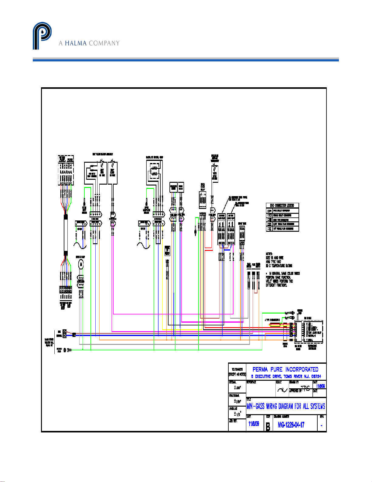
• Refer the drawing MG-1228-04-12. Internally these relays are wired in series to supply power to
the sample pump. To accomplish this, switched line voltage (115,230VAC, Orange wire) is
supplied to the common (term. #5) connection of the low purge flow relay. From the normally
open (term. 3) connection of the low purge flow relay, a brown wire connects to the common
(term. #3) connection of the low temperature relay. From the normally open (term. #3)
connection of the low temperature relay, a gray wire connects to the sample pump. This allows
the pump to start only if both relays are energized.
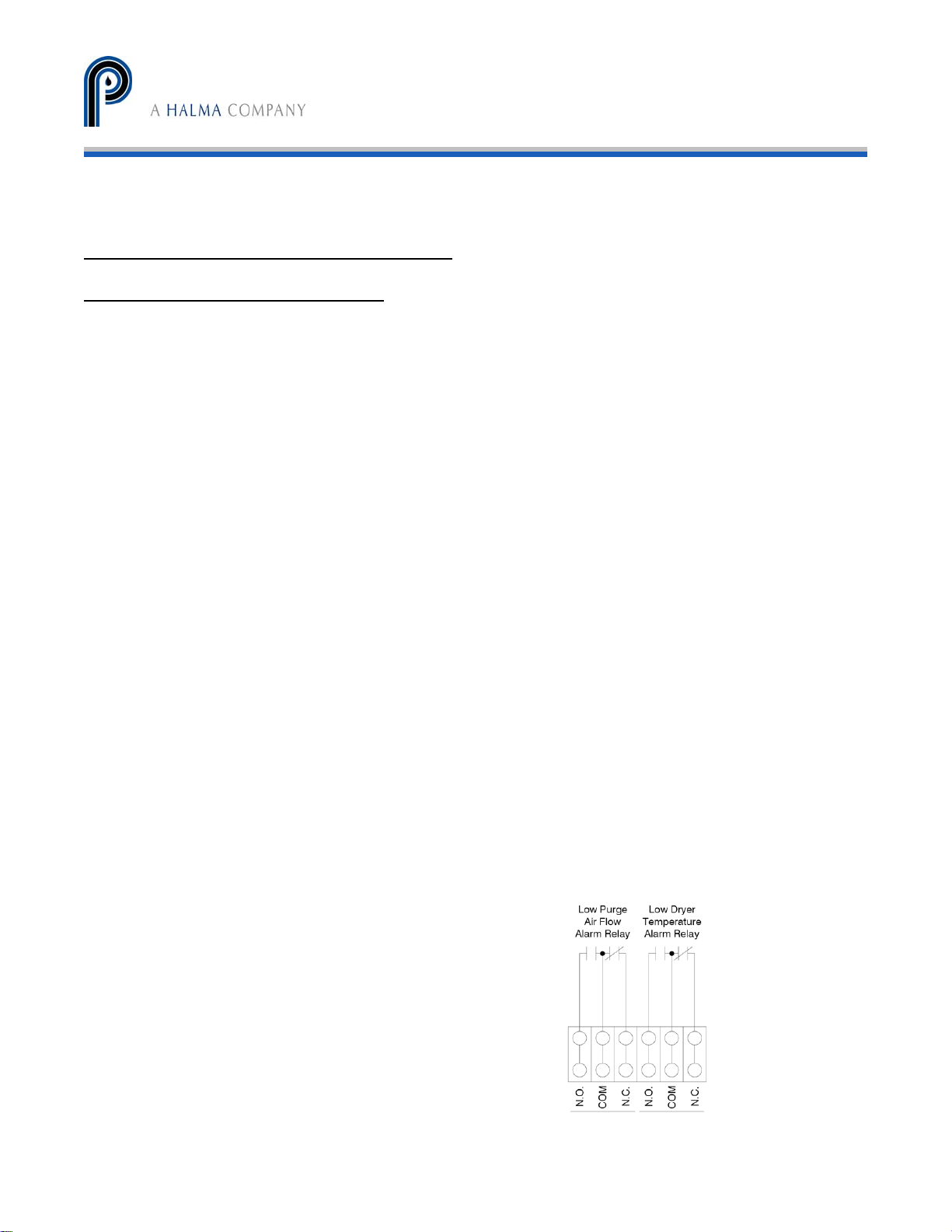
• Refer to Figure 20. For external connection, the second
set of contacts in each relay is “dry”. No power is
applied. This allows the user to determine the control
voltage that will be used. A typical use of the alarm
signal, as described above, is to control sample flow.
The actual use is left up to the customer.
Figure 20
31
Mini-GASS User Manual | Original Instructions
Page 32
PERMA PURE LLC
Mini-GASS™ User’s Manual
Doc. #212: Revision: 00A
Page 32 of 32
Mini-GASS User Manual | Original Instructions
32
 Loading...