

Page 1
Tel: 732-244-0010
Tel: 800-337-3762(toll free US)
Fax: 732-244-8140
Email: info@permapure.com
Web: www.permapure.com
Version 5.01
eCOOL™ 5000XP Series
Digital Thermo-Electric Cooler
Instruction Manual
Page 2

TABLE OF CONTENTS
A: SPECIFICATIONS .......................................................................................................... 3
B: LIMITED WARRANTY .................................................................................................... 4
C: PRINCIPLE OF OPERATION ......................................................................................... 5
D: INSTALLATION .............................................................................................................. 8
E: START-UP PROCEDURE ............................................................................................... 9
F: LEDS & LCD ..................................................................................................................10
G: BOARDS .......................................................................................................................11
H: DEFAULT SETPOINTS ..................................................................................................16
I: “NEW JERSEY” THERMOCOUPLE OPTION ................................................................17
J: MAINTENANCE..............................................................................................................18
K: TROUBLESHOOTING ...................................................................................................19
L: SPARE PARTS: eCOOL™ 5000XP ...............................................................................20
APPENDIX: eCOOL™ 5000XP ..........................................................................................22
Table of Contents 2
Page 3

Model
Standard
Capacity
Heat Exchangers
Passive Active
Dimensions
Weight
Power
Supply
e5500XP
4-7 LPM
8-15 SCFH
1x10 in.
1x10 in.
14 x 13 x 13 in. HWD
36 x 33 x 33 cm HWD
39 lbs
18 kg
240W
e5800XP
7-10 LPM
15-21 SCFH
2x10 in.
14 x 13 x 13 in. HWD
36 x 33 x 33 cm HWD
39 lbs
18 kg
500W
e5900XP
10-20 LPM
21-42 SCFH
2x10 in.
2x10 in.
14 x 13 x 13 in. HWD
36 x 33 x 33 cm HWD
41 lbs
19 kg
500W
Digital Boards
Main control board
Water slip alarm relay board
LAN card (optional)
Filter probe & heated sample line accessory
board (optional)
Heat exchanger thermocouple isolated output
board (optional)
Alarms
Probe over / under temperature
Heated sample line over / under temperature
Cooler over temperature
Cooler thermocouple failure
Water slip (moisture carryover)
Display
Jumbo dual-line LCD
LED red, amber, green heat exchanger status
indicators
Heat Exchanger
Type
EZ-Clean™ twist apart
Heat Exchanger
Material
Stainless steel (standard); Durinert® treated
stainless steel, Kynar®, Glass (optional)
Heat Exchanger
Connections
1/4” FNTP Inlet (first heat exchanger)
1/8” FNTP Outlet
3/8” FNTP Drain
Heat Sink
High heat transfer aluminum
Voltage
120VAC, 50/60Hz, 4.60 Amps
Sample Pump
(Optional)
Model 2PAD-006R dual-head
115VAC, 50/60Hz, 1.03 Amps, 1/14Hp
Drain Pump
(Optional)
Model 3KPB-001 single head peristaltic
Model 3KPB-003 dual head peristaltic
120VAC, 60Hz, 0.52 Amps
Digital Board Specifications
Main Control Board
4 thermocouple inputs
4 analog outputs
Water Slip Alarm Relay
Board
2 water slip (moisture carryover) inputs
2 high current digital contact outputs
2 digital PLC outputs
LAN card (optional)
Modbus or TCP/IP
RJ45 / CAT 5 cable
Filter Probe & Heated
Sample Line Accessory
Board (optional)
2 thermocouple inputs
Pulse width modulated digital output
Heat Exchanger
Thermocouple Isolated
Output Board (optional)
2 thermocouple inputs
2 x 4-20mA outputs
2 x 0-10VDC outputs
Operating Specifications
Maximum Inlet Sample
Temperature
400F (205C) SS, Durinert®, Glass Impingers
280F (138C) Kynar® Impingers
Maximum Inlet Pressure
45 psig
3 bar / 2250 mmHg
Maximum Heat Exchanger
Pressure Drop
<+1 in. H2O
Ambient Temperature
Range
33-104F
0.6-40C
Outlet Sample Gas Dew
Point
41F
5C
A: SPECIFICATIONS
Model Specifications
General Specifications
Section A: Specifications 3
Page 4

B: LIMITED WARRANTY
Perma Pure LLC
WARRANTY and DISCLAIMERS
Perma Pure (Seller) warrants that product supplied hereunder shall, at the time of delivery to Buyer,
conform to the published specifications of Seller and be free from defects in material and
workmanship under normal use and service. Seller’s sole obligation and liability under this warranty is
limited to the repair or replacement at its factory, at Seller’s option, of any such product which proves
defective within one year after the date of original shipment from seller’s factory (or for a normal
usable lifetime if the product is a disposable or expendable item) and is found to be defective in
material or workmanship by Seller’s inspection.
Buyer agrees that (1) any technical advice, information, suggestions, or recommendations given to
Buyer by Seller or any representative of Seller with respect to the product or the suitability or
desirability of the product for an particular use or application are based solely on the general
knowledge of Seller, are intended for information guidance only, and do not constitute any
representation or warranty by Seller that the product shall in fact be suitable or desirable for any
particular use or application; (2) Buyer takes sole responsibility for the use and applications to which
the product is put and Buyer shall conduct all testing and analysis necessary to validate the use and
application to which Buyer puts the product for which Buyer may recommend the use or application of
the product by others; and (3) the characteristics, specifications, and/or properties of the product may
be affected by the processing, treatment, handling, and/or manufacturing of the product by Buyer or
others and Seller takes no responsibility for he nature or consequence of such operations or as to the
suitability of the product for the purposes intended to be used by Buyer or others after being
subjected to such operations.
SELLER MAKES NO OTHER WARRANTY, EXPRESS OR IMPLIED, OF THE PRODUCT
SUPPLIED HEREUNDER, INCLUDING, WITHOUT LIMITATION, IMPLIED WARRANTIES OF
MERCHANTABILITY AND FITNESS FOR PARTICULAR PURPOSE, AND ALL SUCH
WARRANTIES ARE HEREBY EXPRESSLY EXCLUDED. SELLER SHALL HAVE NO LIABILITY
FOR LOSS OF PROFITS, OR SPECIAL, INCIDENTAL, OR CONSEQUENTIAL DAMAGES UNDER
ANY CIRCUMSTANCES OR LEGAL THEORY, WHETHER BASED ON NEGLIGENCE, BREACH
OF WARRANTY, STRICT LIABILITY, TORT, CONTRACT, OR OTHERWISE. SELLER SHALL IN
NO EVENT BE LIABLE IN RESPECT OF THIS ORDER AND OR PRODUCT DELIVERED ON
ACCOUNT OF THIS ORDER FOR ANY AMOUNT GREATER THAN THAT PAID TO SELLER ON
ACCOUNT OF THIS ORDER.
Section B: Limited Warranty 4
Page 5
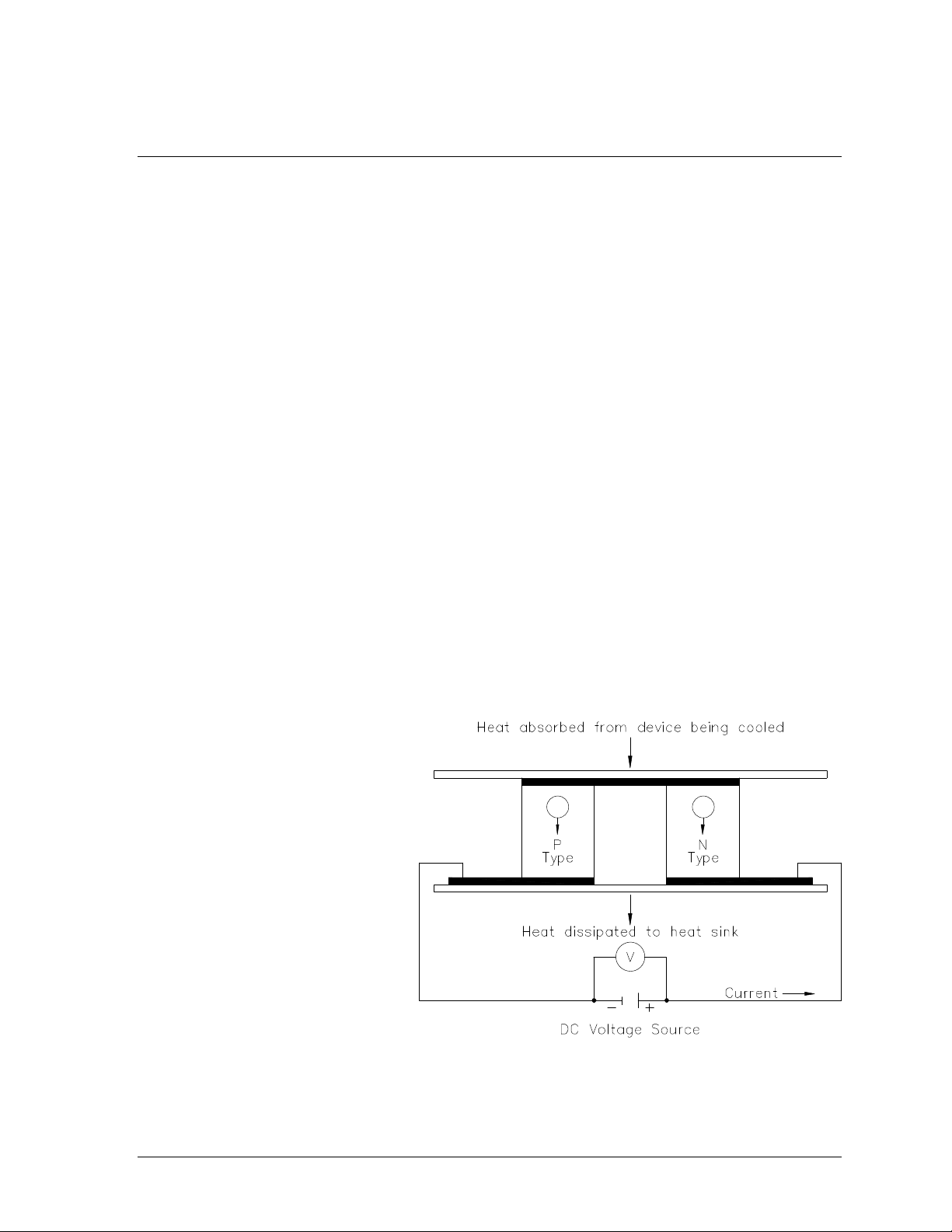
Figure 1: Thermo-electric element (Peltier)
C: PRINCIPLE OF OPERATION
Thank you for purchasing a Perma Pure Baldwin™-Series eCOOL™ 5000XP Series
Digital Thermo-Electric Cooler CSA-C and CSA-US certified for Class I Division 2
Groups A,B,C,D hazardous locations. The eCOOL™ 5000XP Series has numerous
features including:
Remote monitoring and control of heated filter probe, heated sample line, and sample
conditioning system.
eCOOL
Local Area Network.
A jumbo 2-line LCD display with multi-colored LED’s provides easy local monitoring and
control of your sample handling system.
Alarm notification of over / under temperature, thermocouple failure, and water slip
(moisture carryover).
Alarm relay shuts off the sample pump to protect expensive analyzers from water slip
(moisture carryover).
Eliminates the cost and complexity of separate temperature controllers such as for a
heated sample line and filter probe.
Extra thermocouple inputs and outputs available.
Operates with 110/120VAC, 220/240VAC, 12VDC, 15VDC, or 24VDC.
Field friendly, requires virtually no maintenance, and is backed by our 1-year limited
warranty.
All Baldwin-Series coolers use thermo-electric elements (Peltiers) to cool the sample
gas to the desired dew point temperature. A thermo-electric cooler is best illustrated
as a small heat pump with no
moving parts. The Peltiers
operate on direct current and
may be used for heating or
cooling by reversing the
direction of current flow. This is
achieved by moving heat from
one side of the module to the
other with current flow and the
laws of thermodynamics. A
typical single stage Peltier
(figure 1) consists of two
ceramic plates with p- and ntype semiconductor material
(bismuth telluride) between the
™
interface software included for monitoring and control over the Internet or a
plates. The elements of
semiconductor material are
connected electrically in series and thermally in parallel.
Section C: Principle of Operation 5
Page 6
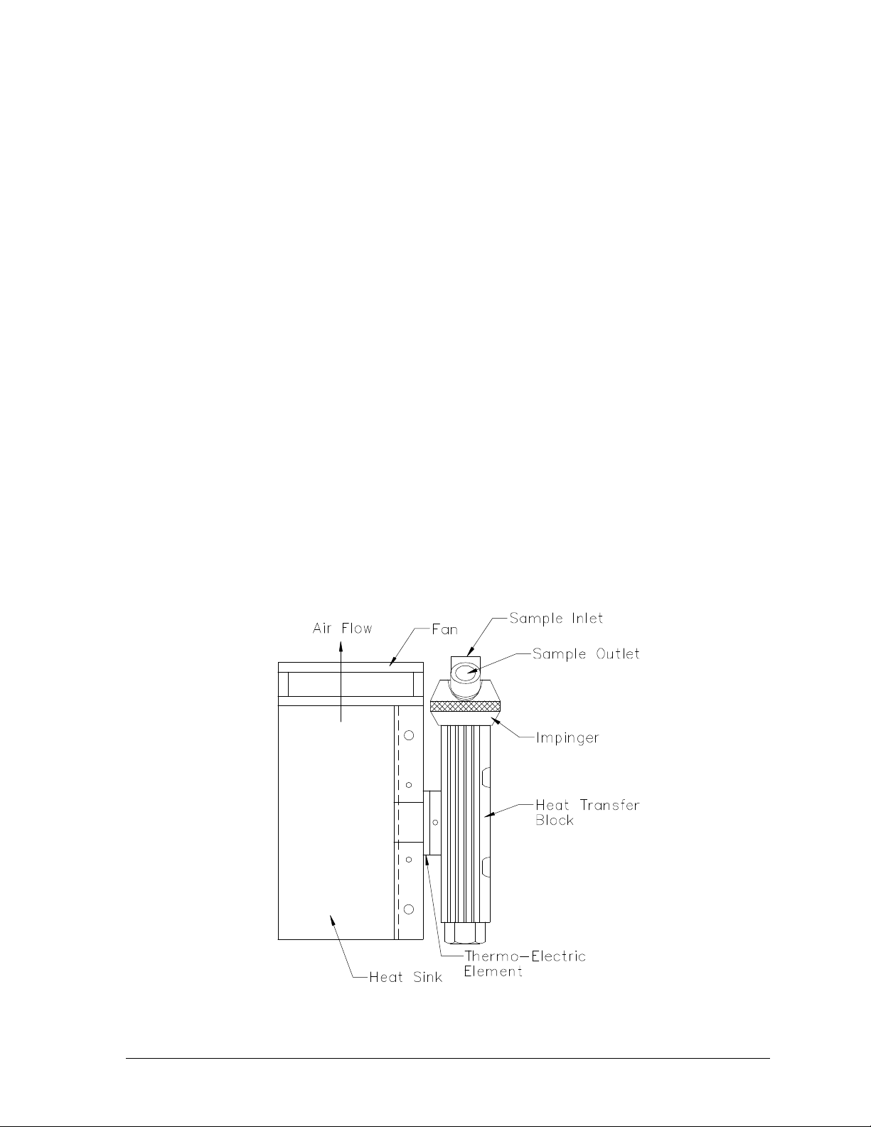
Figure 2: Heat Exchanger, Impinger and Heat Sink Assembly
When a positive DC voltage is applied to the n-type thermo-electric element,
electrons pass from the p- to the n-type thermo-electric element and the cold side
temperature will decrease as heat is absorbed. The heat absorption (cooling) is
proportional to the current and the number of thermo-electric couples. This heat is
transferred to the hot side of the Peltier element where it is dissipated into the heat
sink and surrounding environment.
Baldwin™-Series Thermo-Electric Coolers remove the moisture from the sample gas
by cooling the gas as it passes through a laminar impinger (heat exchanger). A
diagram showing the gas flow path through an impinger is shown in the Appendix.
The heat exchanger, made of 316L stainless steel, Durinert® (a corrosion-resistant
inert coating over 316L stainless steel), PVDF (Kynar®), or glass, is mounted within
a thermally insulated heat transfer block bored to receive the heat exchanger without
a mechanical lock. This assembly allows the easy removal of any heat exchanger
simply by slipping it out of the cooling block by hand. The heat transfer block cools
the heat exchanger through the heat pumping action of the peltier element. The
heat transfer block is on the cold side of the thermo-electric element and the heat
sink is on the hot side of the thermo-electric element. The heat from the heat
transfer block is pumped to the heat sink where it is then dissipated into the air by
the heat sink fan. See figure 2. The desired temperature is maintained by a closed
loop control system, which is implemented through a proportional controller. The
controller uses a type K thermocouple in the heat transfer block located very close to
the cold side of the peltier element as the input sensor.
Section C: Principle of Operation 6
Page 7

The sample gas is passed to the thermo-electric cooler via the heated filter sample
probe and heated sample line. The thermo-electric cooler lowers the sample dew
point to 5°C (41°F). As the gas cools and the moisture vapor condenses, the
condensate exits the heat exchanger through the bottom drain connection.
Particulate matter which passes through the sample cooler is removed by an
optional Perma Pure pre-filter, located downstream from the cooler along with an
optional water slip sensor. The conditioned sample gas can then be directed to the
gas analyzers.
Section C: Principle of Operation 7
Page 8

D: INSTALLATION
WARNING! eCOOL™ 5000XP Digital Thermo-Electric Coolers and related
components must be installed with appropriate conduit and connections for area
classification subject to the local inspection authority having jurisdiction.
eCOOL™ 5000XP Digital Thermo-Electric Coolers should be installed away from
heat sources in a well ventilated area of an instrument rack or enclosure.
Sample tubing connections to the eCOOL™ 5000XP Coolers depend on the heat
exchanger material of construction. A cooler with stainless steel heat exchangers
uses a stainless steel inlet fitting on the first heat exchanger. All other inlets and
outlets are Kynar® standard compression type tube fittings with Teflon® ferrules.
PVDF (Kynar®) heat exchangers use all Kynar® standard compression type tube
fittings with Teflon® ferrules. Perma Pure cannot warrantee against damage to the
Peltier elements or heat exchangers if our supplied Kynar® tube fittings are not used.
CAUTION: If using a stainless steel sample line, place 2 inches of Teflon® tubing in
between the exchanger inlet fitting and the heated line. This prevents the sample
cooler from heat sinking the incoming heated line, which adds undue load to the
cooler.
The inlet and outlet tubing of all metal or Kynar® heat exchangers is 1/4" NPT. The
operator should use the compression type fittings. The inlet of the first1 heat
exchanger uses a 3/8” tube x ¼” MNPT, tube connector fitting to mate with most
standard 3/8” sample lines.
For eCOOL™ 5000XP models that utilize passive/active heat exchangers (i.e.,
e5500XP), the sample pump should be installed after the cooler to protect the pump
head from moisture and ensure longer diaphragm life. The sample pump should be
installed between the heat exchangers in active/active models (e5800XP, e5900XP).
This will assist in water removal by pressurizing the downstream heat exchanger.
There will be minimal sacrifice in pump diaphragm life since the majority of water will
be removed by the first active heat exchanger. It is also acceptable for the sample
pump to be installed after active/active coolers.
The condensate drain connections are Kynar® elbows, 3/8” MNPT x 1/4” barbed
tube fittings. A Perma Pure peristaltic drain pump is recommended for water
removal. This pump uses size 17 tubing.
CAUTION: Do not reduce the size of the condensate tubing since doing so restricts
water flow which may result in water slip (moisture carryover) in the sample.
Section D: Installation 8
Page 9

E: START-UP PROCEDURE
WARNING! eCOOL™ 5000XP Digital Thermo-Electric Coolers and related
components must be installed with appropriate conduit for power cords and
connections for area classification subject to the local inspection authority having
jurisdiction.
Plug in the power cord to a properly grounded main circuit. The LCD should display
the actual temperature. The temperature of each channel should fall until it reaches
5C.
If there are no alarms (an alarm condition consists of water slip detection after the
cooler, thermocouple failure, or actual temperature > 10°C), then the LED(s) should
turn to an amber color. This indicates that the alarms are cleared and the user can
press the reset button to begin operation. Once the reset button is pressed, the
LED(s) should turn green indicating that there are no alarms and sample flow can
begin. If the sample pump is wired through the relay board alarm contacts and all
alarms are cleared, the sample pump will start. The sample pump will stop if any
alarms are detected.
Note: Current alarm conditions are displayed on the second line of the LCD.
eCOOL™ 5000XP Thermo-Electric Coolers are virtually maintenance free.
However, in the event of electrical problems, refer to the Troubleshooting section in
this manual.
Section E: Start-up Procedure 9
Page 10

F: LEDS & LCD
Every eCOOL™ 5000XP Series Digital Thermo-Electric Cooler has a jumbo 2-line
LCD display and 2 LED indicators.
Each of the two LED indicators corresponds to an active heat exchanger and will be
colored Green, Amber, or Red:
LED Summary
GREEN: Status OK, Sampling can begin. Sample pump will run.
AMBER: Alarm is no longer present. User must press the reset button to
acknowledge the alarm and return to normal operation.
Sample pump off.
RED: Alarm - see message on LCD screen. Sample pump off.
The top line of the LCD screen displays the temperature of each active heat
exchanger in degrees Celsius (e.g., 5°C). The scrolling bottom line of the LCD
screen displays cooler status, such as alarm messages.
Alarm Summary
Thermocouple failure
Channel over-temperature alarm
Water slip (water detect) alarm
Please refer to the Troubleshooting section of this manual if your cooler displays any
of the alarms above.
.
Section F: LEDs & LCD 10
Page 11

G: BOARDS
Control Board
The control board is the motherboard for the eCOOL system. The control board
handles the majority of the functions for the cooler module. It contains the micro
processor that controls all of the functional areas of the design, as well as the
temperature measurement of the controlled vapor flow as well as the Pulse Width
Modulation (PWM) control of the Peltier elements to cool the vapor.
Inputs:
4 Thermocouple Inputs (Channel 1, Channel 2, and two Spare)
12-24VDC Power Inputs
12-24VDC Control Board Power Inputs
1 Analog Input
Input/Outputs:
Relay Board 1 Input/Output
Relay Board 2 Input/Output
LAN Card Input/Output
Accessory Board Input/Output
Isolator Board Input/Output
Outputs:
4 Analog Outputs (scaled 0 to 4.5VDC matching the Thermocouple Inputs)
Peltier Power Outputs (spade terminals)
DC Fan Power Output 1
DC Fan Power Output 2
Power Connections
The board is powered in two locations by a DC power supply rated to handle the
current required by the Peltier elements present in the system. The Peltier power is
supplied via the E1 and E2 lugs, where E2 is connected to the positive terminal and
E1 is connected to ground. The rest of the board is powered by the JP1 power
connector. This connector has two terminals on it with number 1 connected to the
positive DC voltage coming from the power supply and number 2 connected to
ground. The wires that are used to connect to the power supply should be
individually routed back to the power supply to minimize the noise created by the
peltiers.
Fuses
The fuses are labeled as F1, F2, F3. They are self-resetting fuses. If one of the
fuses trips, disconnect all power, identify and correct the problem that caused the
Section G: Boards 11
Page 12

high current draw, and reconnect power. It could take up to 5 minutes for a fuse to
self-reset in a power off state.
Main Control Board Overview
Configuration Switches
The configuration switches identify which components are connected to the system.
They are used by the control firmware to determine how the board is going to
operate in the system. The switches are read at power-up, or when the external
reset switch is activated. The table below identifies the switch positions and their
functions.
Section G: Boards 12
Page 13

SW3
Function
OFF
ON
1
Heated Line Control
OFF
ON
2
Probe Control
OFF
ON
3
Peltiers
1 per channel
2 per channel
4
Channels 1 2
5
Peltier Power Share
Full Power
Power Sharing
6
ISO Channels
Inactive
Displayed
SW2
Function
ON
OFF
1
ICE VCC
Enabled
Disabled
2
JTAG ICE ResetN
Enabled
Disabled
3
Calibration
Enabled
Normal Operation
4
Dflash Res
Enabled
Normal Operation
5
Init Clr
Enabled
Normal Operation
Button Control
The buttons are used to control the calibration settings. Follow the bottom line on
the display to determine the functions in the different modes. The three
combinations that are available are left only, right only, or both. To select the center
option on the bottom line of the display, press both buttons together.
Calibration Menus
The calibration mode allows the board to be setup with min and span points as well
as all of the other configuration information applicable depending on the
configuration switch settings.
Ch1, Ch2, TC1, TC2
Min = 0
Span = 5 degrees C
Max = 8*Span Temp (360°C limit)
The calibration is performed by first calculating the expected settings for the
calibration resistors before entering the calibration operation to get a good starting
point. Then the 0 point is adjusted to the minimum point in the ADCC (memory
chip). The span temperature is then set and the span gain is adjusted to make the
span point 1/8 of the entire range for the temperature measurements.
ChX: MIN = xxC
ChX: SPAN = xxC
Section G: Boards 13
Page 14

ChX:RDY TMP= xxC
ChX:SET TMP= xxC
ChX GAIN=%3u
Probe, Heated Line
Min = 0°C
Span =
Max = 360°C
Calibration is performed by setting the gain of the span circuit to minimal gain then
adjusting the 0 point to the minimum reading from the ADCC. The span temperature
is used to measure the ADCC value and calculate the step size of the ADCC.
ChX: MIN = xxC
ChX: SPAN = xxC
ChX:MIN TMP= xxC
ChX:MAX TMP= xxC
ChX:SET TMP= xxC
ChX: GAIN=%3u
Isolation Channels
Min = 0°C
Max = 25°C
The temperature range for the isolation circuit is 0 to 25°C. The calibration is
performed by first calculating a good starting point for the offset and span resistors.
Then adjust the 0 point to the minimum point in the ADCC. The last step is to set
the input to 25°C and adjust the span gain to achieve the max value in the ADCC.
ChX: MIN = xxC
ChX: MAX = xxC
ChX:MIN TMP= xxC
ChX:MAX TMP= xxC
ChX:SET TMP= xxC
ChX: GAIN=%3u
Water Slip (Moisture Carryover) Relay Board
Note: For the following instructions, typical applications run each of the relays in
series through the Common and Normally Open (NO) contacts.
A: Computer Status Alarms (External PLC monitoring).
Wire computer status alarms to JP4 & JP2. Wire the Common and Normally
Open Contacts in series to a PLC. If an alarm occurs, one or both of these
contacts will open.
Section G: Boards 14
Page 15

B: Sample Pump Control – Water slip, over-temperature, thermocouple failure
alarms.
Wire the Line (hot) power for the sample pump through terminals through JP3
and JP1. Wire the Common and Normally Open (NO) contacts in series. If
an alarm occurs, one or both of these contacts will open.
The sample pump is now in series with the Water Slip (Moisture Carryover) Sensor
and the Ready/Slip/power failure relay, which will only allow the sample pump to
start if conditions are satisfactory (i.e., no water slip, and safe operating temperature
of the sampling system, and no thermocouple failure).
LAN Card
To use the LAN Card, connect the 5 VDC power from the LAN card terminal JP1, to
the Power Out terminal on the Control Board terminal JP29 (+5VDC and GND).
Connect a ribbon cable between JP15 on the Control Board to JP16 on the LAN
Card. Then, connect a Cat 5 Ethernet cable with an RJ45 connector to the LAN
Card. The Ethernet cable should connect to a switch or router on a Local Area
Network (LAN) to run the TCP/IP executive software or connected to a Modbus
server.
Accessory Board
To use the Accessory boards make sure that the shorting jumpers on HDR1 and
HDR2 are shorting pins 3-5, 4-6 on both headers.
The Accessory board connects to JP23 on the cooler board.
Isolated Output Board
To use the ISO boards make sure that the shorting jumpers on HDR1 and HDR2 are
shorting pins 3-5, 4-6 on both headers.
The ISO board connects to JP20 on the cooler board.
Section G: Boards 15
Page 16

H: DEFAULT SETPOINTS
eCOOL™ 5000XP Heat Exchangers:
Setpoint Temperature = 5°C
Run Temperature = 10°C
Cooler must operate below the Run Temperature to avoid the over temperature
alarm condition.
Heated Sample Probe:
Setpoint Temperature = 190°C
High Temperature Alarm = 210°C
Low Temperature Alarm = 120°C
Heated Sample Line:
Setpoint Temperature = 190°C
High Temperature Alarm = 210°C
Low Temperature Alarm = 120°C
LAN Card:
Static IP Addressing: 192.168.45.140
DHCP Disabled.
Relay Card:
Relay contacts are in their Normal state (de-energized state) during an alarm
condition.
Analog output 0-4.5 VDC equates to 0-10°C corresponding to each thermocouple.
Section H: Default Setpoints 16
Page 17

Part No.
Description
3KTC-001
Kit, Thermocouple, NJ Option, Type K, w/Fitting & Sleeve
3KTC-002
Kit, Thermocouple, NJ Option, Type J, w/Fitting & Sleeve
3CCB-026
Circuit Board, eCOOL, Isolator Board
I: “NEW JERSEY” THERMOCOUPLE OPTION
Some air quality management districts (e.g., those in New Jersey and Southern
California) require temperature measurement of the gas stream at the outlet of the
last heat exchanger on the cooler. Perma Pure offers a 1/32-inch diameter
hypodermic-style type K thermocouple that can be inserted into a special heat
exchanger (i.e., it has a small port for insertion of the thermocouple) so the actual
sample dew point temperature can be measured. This is sometimes referred to as
the New Jersey thermocouple outlet temperature option.
If the cooler is run as a single stream, the final heat exchanger will have a New
Jersey thermocouple to sense the temperature inside the heat exchanger. A
quantity of two (2) NJ thermocouples are required when the cooler is used for dualstream simultaneous conditioning.
In the Baldwin™-Series eCOOL™ 5000XP, this New Jersey Thermocouple can be
connected to one of the extra thermocouple inputs for readout. Alternately, for a 420mA output, the optional isolator board should be purchased.
eCOOL™ 5000 Series New Jersey Thermocouple Option
Section I: “New Jersey” Thermocouple Option 17
Page 18

J: MAINTENANCE
Note: Please refer to the Spare Parts section of this manual for part numbers and
descriptions.
Daily
Verify each channel is running at 5°C (+/- 1.5°C).
LED’s should be Green.
Verify cooling fans are running.
Verify that the peristaltic pump is running and water is draining out.
Verify that the sample pump is drawing full flow.
Quarterly
Verify power supply voltage is above 14.5 VDC.
Inspect and clean the EZ-Clean Twist-Apart heat exchangers with de-ionized water.
Depending on the composition of the sample stream, heat exchangers may need to
be cleaned more often.
Inspect and replace the sample pump diaphragm when needed.
Inspect and replace the peristaltic pump tubing.
Inspect the water slip sensor and verify that there is no corrosion or restrictions to
the sensing pins.
Annually
Check and replace the Peltier cooling elements. At room temperature, a Peltier
should have a resistance of 5-10 Ohms. Higher resistance signifies the Peltier is
stressed and could fail soon.
Using a K-type thermocouple simulator, disconnect each thermocouple and simulate
a temperature between 0°C and 10°C. Verify that the readout on the display
matches the temperature to within 0.5°C. If it does not, the cooler needs to be
recalibrated. Contact Perma Pure for the calibration procedure and assistance.
Section J: Maintenance 18
Page 19

Alarm Message
Symptom
Action(s)
Thermocouple
Failure Channel #
Thermocouple is failing or
disconnected
Ensure proper connection to TB6 for Channel 1, TB7 for
Channel 2.
Replace K-type thermocouple.
Water Slip Alarm
Water has slipped passed the
thermo-electric cooler and tripped
the water slip sensor.
Ensure system loading (gas flow and water %) does not
exceed cooler capacity.
Verify that the cooler last impinger is holding a constant
temperature near 5°C.
If a dry sensor still trips the alarm, clean the sensor or
replace if necessary.
Overtemp Alarm
Cooler channel does not maintain a
temperature below 10 degrees C.
Verify that the system loading (gas flow and water %) does
not exceed the cooler capacity.
Verify that each Peltier element is drawing approximately 6
Amps. Replace the Peltier element if the current draw is
low.
Calibrate the temperature inputs using a thermocouple
simulator.
Probe Overtemp
Alarm
Probe temperature has exceeded
the Max Set temperature for the
probe.
Max temp is set too low. Adjust accordingly.
Inlet gas sample temp is too high. Consider installing a
cooling spool piece before the probe.
Inspect for wiring problem that is not allowing the controller
to properly maintain temperature.
Probe Undertemp
Alarm
Probe temperature is below the
Minimum Set temperature for the
probe.
Minimum set temperature is too low. Adjust accordingly.
On initial startup, the Heated Probe was initially below the
minimum temp, but now is above minimum. Press reset to
clear the alarm.
The isolated power source for the heater is disconnected
or off.
The heater is failing, causing the probe to not hold
temperature.
Inspect for wiring problem that is not allowing the controller
to properly maintain temperature.
Heated Line
Overtemp Alarm
Heated Line temperature has
exceeded the Max Set temperature
for the line.
Max set temperature is too low. Adjust accordingly.
Inlet gas sample temp is too high. Consider installing a
gas cooling spool piece before the probe.
Inspect for wiring problem that is not allowing the controller
to properly maintain temperature.
Heated Line
Undertemp Alarm
Heated Line temperature is below
the Minimum Set temperature for
the line.
Min set temperature is too low. Adjust accordingly.
On initial startup, the Heated Line was initially below the
minimum temp, but now is above minimum. Press reset to
clear the alarm.
The heater is failing causing the Heated Line to not hold
temperature.
The isolated power source for the heater is disconnected
or off.
Inspect for wiring problem that is not allowing the controller
to properly maintain temperature.
K: TROUBLESHOOTING
Section J: Troubleshooting 19
Page 20

Problem
Check
Action(s)
No LCD or LED(s)
and no fan.
AC power input.
DC 3A fuse (F1) on control board.
AC 15A fuse on power supply.
Check for +15VDC at P1 & P11 of
control board.
Ensure that AC power is connected.
Replace fuse as necessary.
Replace fuse as necessary.
If low reading, remove wires from P1 & P11, measure at
power supply and replace supply if voltage still is low.
Heat exchanger
remains at Peltier current draw. Should be Replace peltier.
ambient
temperature.
Peltier element current draw.
(Should be above 6 amps.)
Replace Peltier element.
Heat exchanger
frozen and cooler
indicates ambient
temperature.
Thermocouple placement in heat
exchanger block.
Peltier current draw (>6A) for both
elements on that channel.
Ensure proper placement.
Replace Peltier element.
Impinger does not
reach set
temperature, but is
below ready
temperature.
System loading.
Calibration and set temperature
adjustment.
Ensure system loading is not exceeding cooler capacity.
Adjust as necessary.
Heat exchanger
temperature cycles
up and down.
Peltier element connections on
control board.
Ferrite beads on thermocouples
going into terminal TB1 & TB2
Ensure a firm connection on flag connectors on control
board. Ensure system loading is not exceeding cooler
capacity.
Wrap a Ferrite bead around thermocouple wires.
Water carryover in
system.
Heat exchanger temperature.
(Should be below 6°C.)
Ensure system loading is not exceeding cooler capacity.
Pump does not
start. LCD(s) are
green.
Pump electrical connections.
Ensure proper connections.
Replace relay board.
For further service assistance, contact:
Perma Pure LLC
P.O. Box 2105
8 Executive Drive (08755)
Toms River, NJ 08754
Tel: 800-337-3762 (toll free U.S.)
Tel: 732-244-0010
Fax: 732-244-8140
Email: info@permapure.com
or your local representative
Section J: Troubleshooting 20
Page 21

Part No.
Description
3CCB-022
Circuit Board, eCool® 5000, Control Board
2FAN-005
Fan: Muffin, 4” x 1”, 12 VDC
2FAN-007
Fan: Muffin, 6” x 1½”, 12 VDC
3CXD-022
Heat Exchanger, SS, EZ-Clean™ Twist-Apart, 10", Durinert® Coated
3CXG-006
Heat Exchanger: 10” Glass, threaded w/ fittings
3CXK-003
Heat Exchanger: 10” Kynar
3CXS-022
Heat Exchanger, SS, Twist-Apart, 10"
3KPE-004
Peltier Element Kit, 40 mm
1PSD-028
Power Supply, 300W, 24VDC, 12A, Explosion Proof, Class 1, Div 2
3CCB-023
Circuit Board, eCOOL, Relay Board
3CCB-024
Circuit Board, eCOOL, LAN Card
3CCB-025
Circuit Board, eCOOL, Accessory Board
3CCB-026
Circuit Board, eCOOL, Isolator Board
1TTC-001
Thermocouple: Temperature, Control, Type K, 24”
L: SPARE PARTS: eCOOL™ 5000XP
Model e5500XP
Model e5800XP
Model e5900XP
Section L: Spare Parts – Thermo-Electric Coolers 21
Page 22

APPENDIX: eCOOL™ 5000XP
E Cool LAN Card Setup and Configuration
Setup:
1. Start a Hyperterminal session or similar terminal emulation software and configure it to
operate at 57600,8 data bits, No Parity, and 1 Stop Bit.
2. Disconnect power from the E Cool cooler card
3. Connect the E Cool LAN card that is to be configured with the following connectors:
a. JP15 - 10 pin connector to DB9 adapter to serial cable connected to PC.
b. JP16 - 10 pin ribbon cable to JP15 on the E Cool cooler board
c. P1 - Connected to Ethernet Cable
d. JP1 - Connected to +5V power and GND coming from the E Cool cooler board JP29.
4. Apply power to the E Cool cooler card
5. Press the reset button on the E Cool LAN card (SW1)
a. The Hyperterminal window should now have configuration information from the card.
b. The last line should show "ATMEL ok."
6. Add a shorting jumper to JP12 to allow EEPROM configuration
Configuration via terminal program:
1. Type bootinfo to get a list of the current settings for the card
2. Choose to Enable/Disable DHCP
If DHCP is enable, the DHCP server can be setup to assign a specific IP address to the
unique MAC address for the LAN card. The address is found printed on a label on the card.
The MAC address can also be obtained by holding down SW5 on the main control board an
monitoring the LCD display. By assigning the address in the DHCP server the card will get
the same address each time it is powered up.
a. To Enable DHCP enter dhcp enable
b. b.To Disable DHCP enter dhcp disable (factory default)
3. If DHCP is disabled: (factory default values shown)
a. Assign a static IP address
ip 192.168.45.145
b. Assign a DNSserver (if required; no value factory set)
dns xxx.xxx.xxx.xxx
c. Assign a default gateway
gw 192.168.45.100
d. Assign a subnet mask
subnetmask 255.255.255.0
4. Press the reset button on the E Cool LAN card (SW1)
Verify that the card gets either gets an IP address from the DHCP server or contains the
statically assigned IP address by monitoring the terminal program.
5. Remove the shorting jumper from JP12
6. Power down the E Cool controller card
22
 Loading...