


 Use and Care Guide
All Models
(page 2-11)
HP15 15” SIGNATURE SERIES
HP24 24” SIGNATURE SERIES
HP48 48” SIGNATURE SERIES
HH24 SIGNATURE SERIES SOTTILE
HC24 C-SERIES
HA24 ADA-COMPLIANT SERIES
 Guide d'utilisation et d'entretien
Tous les modèles
(page 12-22)
HP15 SÉRIE SIGNATURE 15 po HP24 SÉRIE SIGNATURE 24 po HP48 SÉRIE SIGNATURE 48 po HH24 SÉRIE SIGNATURE SOTTILE HC24 SÉRIE C
HA24 SÉRIE CONFORME ADA
Form No. Z2344
Rev. 06.03.2015

PERLICK RESIDENTIAL INSTALLATION MANUAL |
|
|
|
TABLE OF CONTENTS |
|
|
|
Warranty Information .................................................................. |
2 |
Outdoor Model Start-Up/Winterizing................................ |
7 |
Safety Information.......................................................................... |
4 |
LED/Light Bulb Replacement.................................................. |
7 |
Operation............................................................................................. |
4 |
Stainless Steel Care and Cleaning......................................... |
8 |
Digital Temperature Control..................................................... |
4 |
Product/Replacement Part Information........................... |
9 |
Dial Temperature Control........................................................... |
6 |
Troubleshooting.............................................................................. |
10 |
CONGRATULATIONS
Congratulations on your purchase of a Perlick high quality residential refrigeration product. Perlick’s innovative product offering gives you the opportunity to enjoy the functionality and user friendliness in just about any room of your home, including kitchens, bedrooms, entertainment rooms, basements and even bathrooms.
All Perlick products are built with commercial grade stainless steel, providing you with the beauty and durability for a lifetime of use. This installation guide will show you how to properly install your new perlick product.
We dedicate considerable time to ensure that our products provide the highest level of customer satisfaction. If, however, service is required, call Perlick at 800.558.5592. For your own protection, never return merchandise for credit without our approval.
We thank you again for selecting a high quality Perlick product. We hope you enjoy using it.
PERLICK RESIDENTIAL PRODUCTS WARRANTY
WARRANTY:
Perlick Corporation (“Perlick”) warrants to the original retail purchaser that during the Basic Warranty Period, Perlick’s products will be free from free from defects in material and workmanship, and during the Extended Warranty Period, the hermetically sealed refrigeration system contained in Perlick’s undercounter refrigerator will be free from defects in material and workmanship. This system consists entirely of the compressor, condenser, drier, connecting tubing, evaporator and hot gas bypass valve.
The Basic Warranty Period is as follows:
•For a new product or floor display model, other than the H50IM Clear Ice Maker: The three (3) year period commencing on the date of purchase by the original retail purchaser, except that the Basic Warranty Period will be the two (2) year period commencing on the date of purchase by the original retail purchaser if the purchase of the product is not registered with Perlick within ninety (90) days of purchase in the manner described below.
Model Number: _____________________________________
Serial Number: _ _____________________________________
Purchase Date: _ _____________________________________
Dealer Name/Address:
__________________________________________________
__________________________________________________
__________________________________________________
Phone Number: _ ____________________________________
C US
US 


•For the H50IM Clear Ice Maker or a factory second (B-Stock) product: The one (1) year period commencing on the date of purchase by the original retail purchaser.
The Extended Warranty Period applies only to the hermetically sealed refrigeration system contained in Perlick’s undercounter refrigerators. The Extended Warranty Period is the portion of the six (6) year period commencing on the date of purchase by the original retail purchaser that is not covered by the Basic Warranty Period.
REMEDY:
Perlick will provide the parts and labor necessary to repair or replace (at Perlick’s option) any parts proven to be defective in material or workmanship during the Basic Warranty Period. Perlick will provide the replacement parts, but not the labor, for any parts of the hermetically sealed refrigeration system proven
IMPORTANT!
Read and understand all information in this manual before attempting the installation. All plumbing and electrical work must be performed by a qualified technician and conform to all applicable state and local codes.
2 perlick.com

to be defective in materials or workmanship during the Extended Warranty Period. The cost of freight to ship the replacement parts will be paid by Perlick. Replacement parts are warranted for the remainder of the original warranty period, or ninety (90) days, whichever is longer.
REGISTRATION:
Your Perlick product can be registered via the online Warranty Registration form at http://www.perlick.com/residential- products/service-support/warranty-registration/.
OTHER TERMS AND CONDITIONS:
This Warranty applies only to products installed in the fifty states of the United States, the District of Columbia and the ten provinces of Canada.
To obtain the warranty coverage described in this Warranty, Perlick or its authorized distributor or dealer must receive written notice of the warranty claim within the applicable warranty period. To receive parts and/or service and the name and telephone number of the nearest Perlick authorized service representative, please contact your Perlick dealer or distributor, or Perlick’s Customer Service Department by writing to it at Perlick Corporation, Attn: Customer Service Department, 8300 West Good Hope Road, Milwaukee, Wisconsin 53223; or by calling Perlick’s Customer Service Department at 800-558- 5592; or by e-mailing Perlick’s Customer Service Department at warrantyserv@perlick.com. In addition, you can notify Perlick of a warranty claim by visiting Perlick’s website at http://www. perlick.com/residential-products/service-support/ and filling out and submitting the Technical Service Request form that appears there.
All service provided by Perlick under this Warranty must be performed by Perlick’s authorized service representatives, unless otherwise specified by Perlick in writing. Service will be provided during normal business hours.
This Warranty applies only to the original retail purchaser of the Perlick product, and may not be assigned or transferred.
THIS WARRANTY DOES NOT APPLY TO:
•Damage to Products occurring during transportation.
•Products that are used in a manner that is not normal residential or light commercial use.
•Products that are: improperly installed; misused or abused; operated with low voltage; wired in a manner not conforming to electrical codes; not properly operated in accordance with Perlick’s instructions; not cleaned or maintained in accordance with Perlick’s instructions; modified; or damaged by lightning or other acts of nature.
•Consumable items such as light bulbs.
•Cosmetic damage.
•Adjustments to controls, door reversal, cleaning the condenser or other routine maintenance.
PERLICK RESIDENTIAL INSTALLATION MANUAL
•Products for which the original proof of purchase, delivery date or serial number cannot be verified.
•Products for which the defective parts are not returned for inspection if requested by Perlick.
•Damage to other property caused by the products, including but not limited to loss of food due to spoilage and damage caused by water leakage.
THIS LIMITED WARRANTY IS IN LIEU OF ANY OTHER WARRANTY, EXPRESSED OR IMPLIED, INCLUDING BUT NOT LIMITED TO ANY IMPLIED WARRANTY OF MERCHANTABILITY OR FITNESS FOR A PARTICULAR PURPOSE; PROVIDED HOWEVER, THAT TO THE EXTENT REQUIRED BY LAW, IMPLIED WARRANTIES ARE INCLUDED BUT DO NOT EXTEND BEYOND THE DURATION OF THE EXPRESS WARRANTY FIRST SET ABOVE.
PERLICK’S SOLE LIABILITY AND YOUR EXCLUSIVE REMEDY UNDER THIS WARRANTY ARE SET FORTH IN THE PARAGRAPH ENTITLED “REMEDY” SET FORTH ABOVE.
PERLICK SHALL HAVE NO LIABILITY WHATSOEVER FOR ANY INCIDENTAL, CONSEQUENTIAL OR SPECIAL DAMAGES ARISING FROM THE SALE, USE OR INSTALLATION OF THE PRODUCT OR FROM ANY OTHER CAUSES WHATSOEVER, WHETHER BASED ON WARRANTY (EXPRESS OR IMPLIED) OR OTHERWISE BASED ON CONTRACT, TORT OR ANY OTHER THEORY OF LIABILITY. IN NO EVENT SHALL PERLICK’S LIABILITY WITH RESPECT TO A PRODUCT EXCEED THE PURCHASE PRICE OF THE PRODUCT.
Some states do not allow limitations on how long an implied warranty lasts, or the exclusion or limitation of incidental or consequential damages, so the above limitations and exclusions may not apply to you. This Warranty gives you specific legal rights, and you may also have other rights, which vary from state to state.
SAFETY
PLEASE READ all instructions completely before attempting to install or operate the unit. Take particular note of the
DANGER, WARNING and CAUTION information in the manual. The information is important for the safe and efficient installation, operation and care of your Perlick unit.
 DANGER
Indicates a hazard that WILL result in serious injury or death if precautions are not followed.
 WARNING
Indicates a hazard MAY cause serious injury or death if precautions are not followed.
 CAUTION
Indicates a hazard where minor injury or product damage may occur if precautions are not followed.
perlick.com 3
PERLICK RESIDENTIAL INSTALLATION MANUAL
OPERATION
MASTER SWITCH
Signature Series products come equipped with a master power switch located behind the louvered toe kick. Remove the toe kick to turn power on or off to the unit.
INTERIOR LIGHT
Door units are equipped with an interior light that illuminate when the door is opened. All HP24 and HH24 models come standard with adjustable blue and white LED lighting. HC and HA come with a specialty appliance light located on back wall or ceiling depending on the model. The cabinet also comes equipped with a manual light switch for displaying the products through a glass door.
Always ensure that the manual light switch is in the OFF position before closing a solid wood or stainless steel door. If manual light switch is left on for an extended period of time, it may increase the cabinet temperature, and cause the refrigeration system to run harder.
LOADING PRODUCT
Before storing perishables, turn unit on and allow it to operate for a minimum of 24 hours to allow temperatures to stabilize. When loading items into the unit, do not block internal louvers and fan guard openings or performance will be decreased.
CHECKING PRODUCT TEMPERATURE
1). To accurately check the temperature of product stored in the refrigerated compartment, insert an accurate thermometer into a plastic unbreakable bottle, partially filled with water. Tighten bottle cap securely.
2). Place the bottle in the desired area for 24 hours. Refrain from opening the unit during the testing period. After 24 hours, check the temperature of the water. Adjust the temperature accordingly using the following procedures:
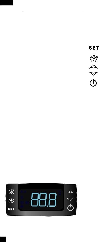
DIGITAL TEMPERATURE CONTROL
Signature Series Models
Figure 1. Digital Temperature Controller
4 perlick.com
Perlick Signature Series, C-Series and ADA Compliant freezer units come standard with state-of-the-art digital control. Please note there are three sets of instructions; one for 24” Signature Series Dual-Zone models, one for C-Series, and another set for 15”, 24” Single-Zone and Sottile, and 48” Signature Series and ADA-Compliant Freezer models.
Programming Button Definitions:
SET button
DEFROST button (melting snowflake)
UP arrow
DOWN arrow
ON/OFF button
Signature Series Dual-Zone Control Instructions
Upper Compartment:
To view the upper compartment temperature, press and release the DEFROST button (melting snowflake).
Lower Compartment (Must be coldest zone):
Display reading always shows the lower compartment temperature.
Setpoint Display:
Press and release the SET button; display will read St1. Press SET again and the LOWER compartment setpoint will be displayed.
Press SET again; the display will read St2. Press SET again and the UPPER compartment temperature will be displayed.
Changing the Lower Compartment Temperature:
1.Press and hold the SET button until the display shows St1 with”F” flashing.
2.Press SET again to display the upper compartment’s current temperature (“F” will continue to flash).
3.Use the UP or DOWN arrow key to scroll to the desired temperature. The controller will memorize the new temperature.
Changing the Upper Compartment Temperature:
1.Press and hold the SET button until the display shows St1 with”F” flashing. Press the DOWN arrow once; the display will read St2,
2.Press SET again to display the upper compartment’s current temperature (“F” will continue to flash).
3.Use the UP or DOWN arrow key to scroll to the desired temperature. The controller will memorize the new temperature.
NOTE: Dependent on the model and configuration, the controllers have been programmed to only allow a temperature adjustment within a specified range. See the chart below for the specified range allowed for your unit.
PERLICK RESIDENTIAL INSTALLATION MANUAL
NOTE: Dependent on the model and configuration, the controllers have been programmed to only allow a temperature adjustment within a specified range. See the chart below for the specified range allowed for your unit.
Signature Series – Dual-Zone Units
Model |
Range (F) |
|
|
HP24D |
Upper 51° - 65° / Lower 45° - 60° |
|
|
Dual-Zone Temperature Scale
To change F to C, press and hold the down arrow for 3 seconds.
Signature Series 15”, 24” Single-Zone and Sottile, and 48” , ADA Freezer Control Instructions
To Set Target Temperature
Press and release the SET button. Display will show the current temperature setpoint.
To Change Setpoint Temperature
1.Press and hold the SET button until the display shows the current setpoint temperature with the “F” flashing.
2.Use the UP and DOWN arrow button to scroll to the desired temperature.
To Start A Manual Defrost (Freezer Models Only)
Press the DEFROST button (melting snowflake)
To Set Maximum Stored Temperature
Press the UP arrow button to see the maximum stored temperature. To reset the maximum stored temperature, while displayed, press and hold the SET button until ‘rst’ flashes in the display.
To Set Minimum Stored Temperature
Press the DOWN arrow button to see the minimum stored temperature. To reset the minimum stored temperature, while displayed, press and hold the SET button until ‘rst’ flashes in the display.
On/Off
Press the ON/OFF button to turn the unit on or off.
Key Combinations:
 +
+

 +
+

 +
+
Press the UP and DOWN arrow buttons to lock and unlock the keyboard
Press the SET and DOWN arrow buttons simultaneously to enter programming mode.
Press the SET and UP arrow buttons simultaneously to return to room temperature display.
Signature Series – HP15 Models
Model |
|
Min Temp Set |
Max Temp Set |
|
|
|
|
HP15R |
|
33° F |
42° F |
|
|
|
|
HP15B |
|
33° F |
48° F |
HP15W |
|
45° F |
65° F |
|
|
|
|
HP15T |
|
33° F |
42° F |
|
|
|
|
Signature Series – HP24 Models |
|
||
Model |
|
Min Temp Set |
Max Temp Set |
|
|
|
|
HP24R |
|
33° F |
42° F |
|
|
|
|
HP24F |
|
-10° F |
10° F |
HP24B |
|
33° F |
48° F |
|
|
|
|
HP24W |
|
45° F |
65° F |
|
|
|
|
HP24T |
|
33° F |
42° F |
Signature Series – HP48 Models |
|
||
|
|
|
|
Model |
|
Min Temp Set |
Max Temp Set |
|
|
|
|
HP48WO |
|
40° F |
65° F |
HP48WW |
|
40° F |
65° F |
|
|
|
|
Signature Series Sottile |
|
|
|
|
|
|
|
Model |
|
Min Temp Set |
Max Temp Set |
HH24RS |
|
33° |
42° |
|
|
|
|
HH24BS |
|
33° |
48° |
|
|
|
|
HH24WS |
|
45° |
65° |
ADA-Compliant Series |
|
|
|
|
|
|
|
Model |
|
Min Temp Set |
Max Temp Set |
|
|
|
|
HA24FB |
|
-10° |
10 |
LED Functions
The following table describes LED functions
LED |
Mode |
Function |
|
ON |
Compressor is on |
|
Flashing |
Anti-short cycle |
|
|
delay is on |
|
ON |
Defrost is on |
|
ON |
Alarm is on |
|
Flashing |
You are in the process of |
|
|
programming the unit |
perlick.com 5
PERLICK RESIDENTIAL INSTALLATION MANUAL
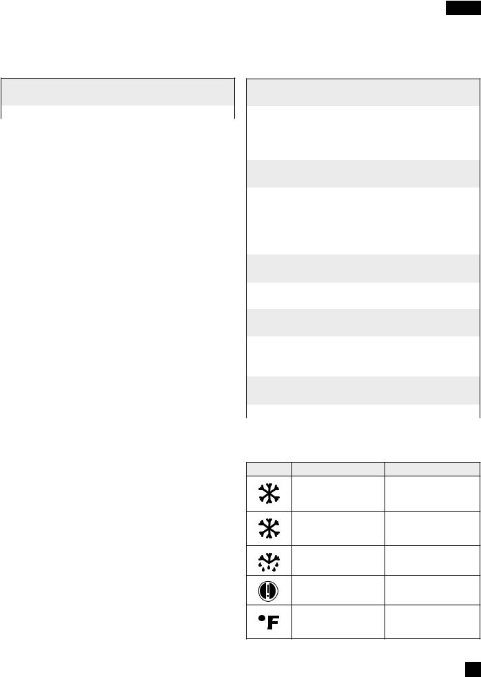
DIGITAL TEMPERATURE CONTROL
C-Series Models
Figure 2. nEW 961 Digital Temperature Controller
Perlick C-Series units come standard with digital control.
Programming Button Definitions:
|
STAND-BY (ESC) |
|
SET (ENTER) |
|
Press and release |
Press and release |
|||
• Opens Machine Status menu |
||||
• Returns to the previous |
||||
|
and displays alarms (if active) |
|||
|
menu level |
|
||
|
Press for at least 5 sec. |
|||
• |
Confirms parameter value |
|||
• |
Opens Programming menu |
|||
Press for at least 5 sec. |
||||
• |
Confirm commands |
|||
• |
Activates the Standby |
|||
|
|
|||
|
function (off ) (When |
|
|
|
|
outside the menus) |
|
|
|
|
|
|
|
|
|
UP |
|
DOWN |
|
Press and release |
Press and release |
|||
• |
Scroll menu items |
• |
Scroll menu items |
|
• |
Increases values |
• |
Decreases values |
|
Press for at least 5 sec. |
Press for at least 5 sec. |
|||
• |
Activates the Manual |
• Function can be configured |
||
|
Defrost function |
|
by the user |
|
|
|
|
|
|
To Change Setpoint Temperature
1.Press  . “SP” will be displayed. Press
  again to display current setpoint temperature.
2.Press  and
and  to modify it and
  or
or  to save the change.
On/Off
To turn the unit off, press and hold  for at least 5 seconds. “OF” will be displayed. To turn the unit on again, press and hold
 for at least 5 seconds.
NOTE: Dependent on the model and configuration, the controllers have been programmed to only allow a temperature adjustment within a specified range. See the chart below for the specified range allowed for your unit.
C-Series Models
Model |
Temp Range |
HC24R |
33° - 42° F |
|
|
HA24BB |
33° - 48° F |
|
|
HA24WB |
45° - 65° F |
LED Functions
The following table describes LED Funtions
Defrost LED |
Alarm LED |
Permanently on: defrost active |
Permanently on: alarm active |
Flashing: manual defrost active |
Flashing: alarm acknowledged |
Off: otherwise |
Off: otherwise |
Evaporator LED |
Compressor LED |
Permanently on: fans active |
Permanently on: compressor active |
Off: otherwise |
Flashing: a delay, a protection or a |
|
locked start-up |
|
Off: otherwise |
Aux LED |
°C LED |
Permanently on: Aux output |
Permanently on: display the |
active |
temperature |
Off: otherwise |
Off: otherwise |
NOTE: When switched on, the device performs a Lamp Test; the display and LEDs will flash for several seconds to check that they all function correctly.
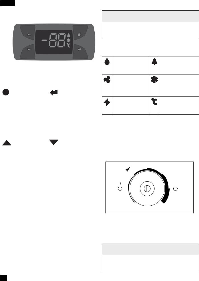
DIAL TEMPERATURE CONTROL
ADA-Compliant Models
(Excludes ADA Freezer - HA24F models use digital controller found on page 5)
4
|
|
E |
R |
3 |
5 |
|
L |
|
|||
O |
|
|
|
||
|
|
|
|
||
|
|
|
|
|
|
O |
|
|
|
|
|
C |
|
|
|
|
|
|
|
|
2 |
|
6 |
1
COLD
OFF
Figure 3. Dial Temperature Controller
Use a straight slot screwdriver to adjust the dial temperature control. The control is located at the top rear panel of the cabinet. Approximate temperature ranges are as follows:
ADA-Compliant Series
Model |
Temp Range |
HA24RB |
33° - 42° F |
|
|
HA24BB |
35° - 48° F |
|
|
HA24WB |
45° - 65° F |
6 perlick.com

Adjust the temperature as follows:
Colder Temperature:
Turn the adjusting screw clockwise (to the right).
Warmer Temperature:
Turn the adjusting screw counterclockwise (to the left).
Temperature Control OFF:
Turn the adjusting screw completely counterclockwise to the OFF position until a click is heard.
NOTE: The condenser fan motor turns off with the compressor.
MAINTENANCE
SEASONAL MAINTENANCE FOR UL-APPROVED OUT- DOOR MODELS
Winterizing
This process should occur when the daily low temperatures is at or below the temperatures stated below:
Freezer models: 32° F Refrigerator models: 38° F Beverage Center: 42° F Wine Reserve: 45° F
It is best to winterize your unit before the low temperatures listed above.
1.Turn the unit to OFF position by pressing the OFF button on the controller. The controller displays the word “OFF” and, for Signature Series models, turn the master switch located behind the grille off (if the power cord is accessible, unplug the power cord. If not, turn off the circuit breaker to the electrical receptacle the cabinet is plugged into). For C-Series units, unplug or turn off the circuit breaker.
2.Remove all contents from the unit.
3.Remove the front grille.
4.Clean the condenser by using a vacuum cleaner to remove loose debris (leaves, dirt, etc.) that may have accumulated inside the grille.
5.Reinstall the front grille.
6.Clean the interior of the unit using stainless steel cleaner and polish (see page 9).
7.Clean the exterior of the unit using stainless steel cleaner and polish (see page 9).
NOTE: Do not place a cover over the unit. While not required, you may choose to remove the unit from the outdoor location and store indoors.
PERLICK RESIDENTIAL INSTALLATION MANUAL
 CAUTION
Operating the unit at temperatures lower than those recommended will void the warranty.
Spring Start-Up
This process should occur after the daily low temperatures is below the temperatures stated below:
Freezer models: 32° F Refrigerator models: 38° F Beverage Center: 42° F Wine Reserve: 45° F
1.Remove the grille.
2.Check the condensing unit to ensure it is clear of loose debris, and clean as necessary with a vacuum cleaner.
3.Reattach front grille to the unit.
4.Clean the interior of the unit using stainless steel cleaner and polish (see page 9).
5.Clean the exterior of the unit using stainless steel cleaner and polish (see page 9).
6.Plug the unit into the electrical receptacle or turn on the circuit breaker.
7.Turn on the master switch located behind the grille if model is Signature Series. Press the OFF button one time to turn the unit on. The controller display will show the actual temperature inside the cabinet.
8.The cooling process will begin to bring the unit to the set temperature. It’s recommended you run the unit for 24 hours to stabilize the operating temperature before using.
 DANGER
Never attempt to repair or perform maintenance on the unit until the main electrical power to the unit has been disconnected!
LED REPLACEMENT (SIGNATURE SERIES)
Call your Perlick Factory Authorized Service Center. For the location of the Service Center in your area, contact your selling dealer, inquire via the web at www.perlick.com, E-mail us at warrantyserv@perlick.com, or call
(800) 558-5592 during normal business hours.
LIGHT BULB REPLACEMENT (C-SERIES, ADA-COMPLIANT & SHALLOW-DEPTH SERIES)
To replace a defective or burnt out bulb, remove the glass light cover by pulling out on the cover, unscrew the bulb and replace it with an identical or smaller bulb. The Perlick replacement part number is 67026.
perlick.com 7
 Loading...